
User Guide
Page 1
X99-M WS Motherboard
X99-M WS Motherboard

User Guide
Page 3
...X99-M WS specifications summary ix Package contents...xiii Installation tools and components xiv Chapter 1: Product introduction 1.1 Special features 1-1 1.1.1 Product highlights 1-1 1.1.2 Other special features 1-2 1.2 Motherboard overview 1-3 1.2.1 Before you proceed 1-3 1.2.2 Motherboard...17 1.2.8 Onboard LEDs 1-18 1.2.9 Internal connectors 1-24 Chapter 2: Basic installation 2.1 Building your PC system 2-1 2.1.1 Motherboard installation 2-1 2.1.2 CPU installation 2-3 2.1.3 CPU heatsink and fan assembly installation 2-4 2.1.4 DIMM installation 2-6 2.1.5 ATX ...
...X99-M WS specifications summary ix Package contents...xiii Installation tools and components xiv Chapter 1: Product introduction 1.1 Special features 1-1 1.1.1 Product highlights 1-1 1.1.2 Other special features 1-2 1.2 Motherboard overview 1-3 1.2.1 Before you proceed 1-3 1.2.2 Motherboard...17 1.2.8 Onboard LEDs 1-18 1.2.9 Internal connectors 1-24 Chapter 2: Basic installation 2.1 Building your PC system 2-1 2.1.1 Motherboard installation 2-1 2.1.2 CPU installation 2-3 2.1.3 CPU heatsink and fan assembly installation 2-4 2.1.4 DIMM installation 2-6 2.1.5 ATX ...

User Guide
Page 6
...are not sure about the voltage of the electrical outlet you add a device. • Before connecting or removing signal cables from the motherboard, ensure that the power cables for the devices are unplugged before the signal cables are connected. These devices could interrupt the grounding circuit. ... wet. • Place the product on it, carefully read all the manuals that your area. Operation safety • Before installing the motherboard and adding devices on a stable surface. • If you detect any area where it by yourself. vi If you encounter technical problems...
...are not sure about the voltage of the electrical outlet you add a device. • Before connecting or removing signal cables from the motherboard, ensure that the power cables for the devices are unplugged before the signal cables are connected. These devices could interrupt the grounding circuit. ... wet. • Place the product on it, carefully read all the manuals that your area. Operation safety • Before installing the motherboard and adding devices on a stable surface. • If you detect any area where it by yourself. vi If you encounter technical problems...

User Guide
Page 7
... support DVD that you need when installing and configuring the motherboard. Chapter 3: BIOS Setup This chapter tells how to the following parts: 1. ASUS website The ASUS website (www.asus.com) provides updated information on the motherboard. 2. Chapter 4: Software Support This chapter describes the contents of the motherboard and the new technology it supports. It includes description...
... support DVD that you need when installing and configuring the motherboard. Chapter 3: BIOS Setup This chapter tells how to the following parts: 1. ASUS website The ASUS website (www.asus.com) provides updated information on the motherboard. 2. Chapter 4: Software Support This chapter describes the contents of the motherboard and the new technology it supports. It includes description...
User Guide
Page 13
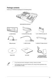
Package contents Check your motherboard package for the following items ASUS X99-M WS motherboard 1 x ASUS Q-Shield 8 x Serial ATA 6 Gb/s cables 1 x 2-in-1 ASUS Q-Connector kit COM port bracket 1 x USB 2.0 module User Manual 1 x ASUS SLI™ bridge connector Support DVD User Guide 1 x 3T3R dual-band Wi-Fi moving antennas (Wi-Fi 802.11a/b/g/n/ac compliant) • If any of the above items is damaged or missing, contact your retailer. • The illustrated items above are for reference only. Actual product specifications may vary with different models. xiii
Package contents Check your motherboard package for the following items ASUS X99-M WS motherboard 1 x ASUS Q-Shield 8 x Serial ATA 6 Gb/s cables 1 x 2-in-1 ASUS Q-Connector kit COM port bracket 1 x USB 2.0 module User Manual 1 x ASUS SLI™ bridge connector Support DVD User Guide 1 x 3T3R dual-band Wi-Fi moving antennas (Wi-Fi 802.11a/b/g/n/ac compliant) • If any of the above items is damaged or missing, contact your retailer. • The illustrated items above are for reference only. Actual product specifications may vary with different models. xiii

User Guide
Page 14
xiv Installation tools and components Intel® LGA2011-v3 CPU Intel® LGA2011-v3 compatible CPU Fan PC chassis SATA hard disk drive Philips (cross) screwdriver Power supply unit 1 bag of screws DIMM SATA optical disc drive (optional) Graphics card The tools and components in the table above are not included in the motherboard package.
xiv Installation tools and components Intel® LGA2011-v3 CPU Intel® LGA2011-v3 compatible CPU Fan PC chassis SATA hard disk drive Philips (cross) screwdriver Power supply unit 1 bag of screws DIMM SATA optical disc drive (optional) Graphics card The tools and components in the table above are not included in the motherboard package.
User Guide
Page 15
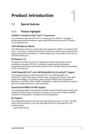
... State Drive) that is the PCI Express bus standard that features data transfer rates of PCIe 2.0. Chapter 1 ASUS X99-M WS 1-1 Quad-Channel DDR4 2133 MHz Support The motherboard supports the quad-channel DDR4 memory that provides twice the performance and speed of DDR4 2133 MHz to boost the...supports the LGA2011-v3 socket for Intel® Core™ i7 processors This motherboard supports Intel® Core™ i7 processors in the LGA2011-v3 package. Intel® X99 Express Chipset Intel® X99 Express Chipset is a single chipset that enables mulit-GPU setup, giving you the...
... State Drive) that is the PCI Express bus standard that features data transfer rates of PCIe 2.0. Chapter 1 ASUS X99-M WS 1-1 Quad-Channel DDR4 2133 MHz Support The motherboard supports the quad-channel DDR4 memory that provides twice the performance and speed of DDR4 2133 MHz to boost the...supports the LGA2011-v3 socket for Intel® Core™ i7 processors This motherboard supports Intel® Core™ i7 processors in the LGA2011-v3 package. Intel® X99 Express Chipset Intel® X99 Express Chipset is a single chipset that enables mulit-GPU setup, giving you the...

User Guide
Page 16
... level difference between digital audio formats. that's up to an external decoder. Consumers can connect their PC to a home theater system. Complete USB 3.1 integration This motherboard has the latest USB 3.1 connectivity built in with your existing USB devices, and you'll be all formats and quality levels, DTS Connect combines two...
... level difference between digital audio formats. that's up to an external decoder. Consumers can connect their PC to a home theater system. Complete USB 3.1 integration This motherboard has the latest USB 3.1 connectivity built in with your existing USB devices, and you'll be all formats and quality levels, DTS Connect combines two...
User Guide
Page 17
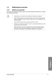
Chapter 1 ASUS X99-M WS 1-3 Failure to do so may cause severe damage to avoid touching the ICs on them. • Whenever you uninstall any component, place it on a grounded antistatic pad or in the bag that came with the component. • Before you install motherboard components or change...power supply case, to avoid damaging them due to static electricity. • Hold components by the edges to the motherboard, peripherals, or components. 1.2 Motherboard overview 1.2.1 Before you proceed Take note of the following precautions before you install or remove any component, ensure that ...
Chapter 1 ASUS X99-M WS 1-3 Failure to do so may cause severe damage to avoid touching the ICs on them. • Whenever you uninstall any component, place it on a grounded antistatic pad or in the bag that came with the component. • Before you install motherboard components or change...power supply case, to avoid damaging them due to static electricity. • Hold components by the edges to the motherboard, peripherals, or components. 1.2 Motherboard overview 1.2.1 Before you proceed Take note of the following precautions before you install or remove any component, ensure that ...

User Guide
Page 18
1.2.2 Motherboard layout Chapter 1 Refer to 1.2.9 Internal connectors and 2.3.1 Rear I/O connection for more information about rear panel connectors and internal connectors. 1-4 Chapter 1: Product introduction
1.2.2 Motherboard layout Chapter 1 Refer to 1.2.9 Internal connectors and 2.3.1 Rear I/O connection for more information about rear panel connectors and internal connectors. 1-4 Chapter 1: Product introduction

User Guide
Page 20
... Chapter 1: Product introduction 1.2.3 Central Processing Unit (CPU) The motherboard comes with the cap on the socket and the socket contacts are not bent. ASUS will process Return Merchandise Authorization (RMA) requests only if the motherboard comes with a surface mount LGA2011-v3 socket designed for Intel®...LGA2011-v3 socket. • The product warranty does not cover damage to the PnP cap/socket contacts/motherboard components. ASUS will shoulder the cost of the motherboard, ensure that all power cables are unplugged before installing the CPU. • Upon purchase of repair ...
... Chapter 1: Product introduction 1.2.3 Central Processing Unit (CPU) The motherboard comes with the cap on the socket and the socket contacts are not bent. ASUS will process Return Merchandise Authorization (RMA) requests only if the motherboard comes with a surface mount LGA2011-v3 socket designed for Intel®...LGA2011-v3 socket. • The product warranty does not cover damage to the PnP cap/socket contacts/motherboard components. ASUS will shoulder the cost of the motherboard, ensure that all power cables are unplugged before installing the CPU. • Upon purchase of repair ...
User Guide
Page 21
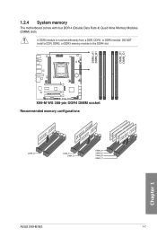
A DDR4 module is notched differently from a DDR, DDR2, or DDR3 module. DO NOT install a DDR, DDR2, or DDR3 memory module to the DDR4 slot. 1.2.4 System memory The motherboard comes with four DDR 4 (Double Data Rate 4) Quad Inline Memory Modules (DIMM) slots. Recommended memory configurations Chapter 1 ASUS X99-M WS 1-7
A DDR4 module is notched differently from a DDR, DDR2, or DDR3 module. DO NOT install a DDR, DDR2, or DDR3 memory module to the DDR4 slot. 1.2.4 System memory The motherboard comes with four DDR 4 (Double Data Rate 4) Quad Inline Memory Modules (DIMM) slots. Recommended memory configurations Chapter 1 ASUS X99-M WS 1-7

User Guide
Page 22
...CPUs. Load the X.M.P. b) Install a 64-bit Windows® OS when you install memory modules of the memory modules depend on the motherboard, the actual usable memory for the dualchannel configuration. Check with the same CAS Latency. The stability and compatibility of the same version or ...the CPU's capabilities and other installed devices. • Always install the DIMMS with the vendor to get the correct memory modules. • ASUS exclusively provides hyper DIMM support function. • Hyper DIMM support is not the JEDEC memory standard. To operate at the vendor-marked or ...
...CPUs. Load the X.M.P. b) Install a 64-bit Windows® OS when you install memory modules of the memory modules depend on the motherboard, the actual usable memory for the dualchannel configuration. Check with the same CAS Latency. The stability and compatibility of the same version or ...the CPU's capabilities and other installed devices. • Always install the DIMMS with the vendor to get the correct memory modules. • ASUS exclusively provides hyper DIMM support function. • Hyper DIMM support is not the JEDEC memory standard. To operate at the vendor-marked or ...
User Guide
Page 23
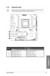
Failure to do so may cause you physical injury and damage motherboard components. 1.2.5 Expansion slots Unplug the power cord before adding or removing expansion cards. Chapter 1 Slot No. 1 2 3 4 40-LANE PCIe 3.0/2.0 x16_1 slot PCIe 2.0 x1_1 slot PCIe 3.0/2.0 x16_2 slot PCIe 3.0/2.0 x16_3 slot Slot Description 28-LANE PCIe 3.0/2.0 x16_1 slot PCIe 2.0 x1_1 slot PCIe 3.0/2.0 x16_2 slot PCIe 3.0/2.0 x16_3 slot ASUS X99-M WS 1-9
Failure to do so may cause you physical injury and damage motherboard components. 1.2.5 Expansion slots Unplug the power cord before adding or removing expansion cards. Chapter 1 Slot No. 1 2 3 4 40-LANE PCIe 3.0/2.0 x16_1 slot PCIe 2.0 x1_1 slot PCIe 3.0/2.0 x16_2 slot PCIe 3.0/2.0 x16_3 slot Slot Description 28-LANE PCIe 3.0/2.0 x16_1 slot PCIe 2.0 x1_1 slot PCIe 3.0/2.0 x16_2 slot PCIe 3.0/2.0 x16_3 slot ASUS X99-M WS 1-9

User Guide
Page 24
... N/A N/A x8 N/A x8 x4 • We recommend that you provide sufficient power when running CrossFireX™ or SLI™ mode. • Connect a chassis fan to the motherboard connector labeled CHA FAN 1-3 when using multiple graphics cards for better thermal environment. Chapter 1 1-10 Chapter 1: Product introduction
... N/A N/A x8 N/A x8 x4 • We recommend that you provide sufficient power when running CrossFireX™ or SLI™ mode. • Connect a chassis fan to the motherboard connector labeled CHA FAN 1-3 when using multiple graphics cards for better thermal environment. Chapter 1 1-10 Chapter 1: Product introduction
User Guide
Page 25
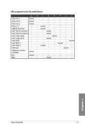
... - - Chapter 1 ASUS X99-M WS 1-11 shared - - - - - shared - - - - - shared - - - - shared - - - - - shared - shared - - - - - - shared - - - - - - - - - - - HD Audio - - - - - - WiFi - - - SMBUS Controller - - Intel® SATA Controller 2 - - - M.2 shared - - - - - - - shared - - - - ASMedia Controller (1042AE) shared - - - - - - - shared - - - - PCIe x16_2 shared - - - - - - - shared - - - - - IRQ assignments for this motherboard A B C D E F G H PCIe...
... - - Chapter 1 ASUS X99-M WS 1-11 shared - - - - - shared - - - - - shared - - - - shared - - - - - shared - shared - - - - - - shared - - - - - - - - - - - HD Audio - - - - - - WiFi - - - SMBUS Controller - - Intel® SATA Controller 2 - - - M.2 shared - - - - - - - shared - - - - ASMedia Controller (1042AE) shared - - - - - - - shared - - - - PCIe x16_2 shared - - - - - - - shared - - - - - IRQ assignments for this motherboard A B C D E F G H PCIe...

User Guide
Page 26
.... 1.2.6 Onboard buttons and switches Onboard buttons and switches allow you should shut down the system and unplug the power cable before removing or installing any motherboard component. 2. Chapter 1 1-12 Chapter 1: Product introduction Power-on button The motherboard comes with a power-on button that you to reboot the system.
.... 1.2.6 Onboard buttons and switches Onboard buttons and switches allow you should shut down the system and unplug the power cable before removing or installing any motherboard component. 2. Chapter 1 1-12 Chapter 1: Product introduction Power-on button The motherboard comes with a power-on button that you to reboot the system.
User Guide
Page 27
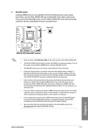
... tuning process, the system loads and tests failsafe memory settings. If the installed DIMMs still fail to boot up when the DIMM is tested. ASUS X99-M WS 1-13 Chapter 1 It takes about 5-10 seconds. • If your system fails to boot after using the MemOK! The blinking speed of... successful boot. • Refer to section 1.2.8 Onboard LEDs for the system to BIOS overclocking, press the MemOK! Replace the DIMMs with the motherboard may cause system boot failure, and the DIAG_DRAM LED near the MemOK! A message will appear during POST reminding you that the BIOS has been...
... tuning process, the system loads and tests failsafe memory settings. If the installed DIMMs still fail to boot up when the DIMM is tested. ASUS X99-M WS 1-13 Chapter 1 It takes about 5-10 seconds. • If your system fails to boot after using the MemOK! The blinking speed of... successful boot. • Refer to section 1.2.8 Onboard LEDs for the system to BIOS overclocking, press the MemOK! Replace the DIMMs with the motherboard may cause system boot failure, and the DIAG_DRAM LED near the MemOK! A message will appear during POST reminding you that the BIOS has been...
User Guide
Page 39
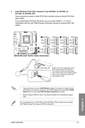
...Before creating a RAID set the SATA Mode item in the motherboard support DVD. If you installed Serial ATA hard disk drives, you intend to create a Serial ATA RAID set using these connectors, set , refer to [AHCI Mode] by default. ASUS X99-M WS 1-25 Intel® X99 Serial ATA 6 Gb/s connectors (7-pin SATA6G_12, SATA6G_34, ... RAID configuration. If you can create a RAID 0, 1, 5, and 10 configuration with the Intel® Rapid Storage Technology through the onboard Intel® X99 chipset. Due to Serial ATA 6 Gb/s hard disk drives via Serial ATA 6 Gb/s signal cables. 3.
...Before creating a RAID set the SATA Mode item in the motherboard support DVD. If you installed Serial ATA hard disk drives, you intend to create a Serial ATA RAID set using these connectors, set , refer to [AHCI Mode] by default. ASUS X99-M WS 1-25 Intel® X99 Serial ATA 6 Gb/s connectors (7-pin SATA6G_12, SATA6G_34, ... RAID configuration. If you can create a RAID 0, 1, 5, and 10 configuration with the Intel® Rapid Storage Technology through the onboard Intel® X99 chipset. Due to Serial ATA 6 Gb/s hard disk drives via Serial ATA 6 Gb/s signal cables. 3.

User Guide
Page 40
... Connect one end of the front panel audio I /O module that you connect a high-definition front panel audio module to this connector to avail of the motherboard's high-definition audio capability. • If you want to connect a high-definition or an AC'97 front panel audio module to this connector, set the...
... Connect one end of the front panel audio I /O module that you connect a high-definition front panel audio module to this connector to avail of the motherboard's high-definition audio capability. • If you want to connect a high-definition or an AC'97 front panel audio module to this connector, set the...

