
Terminator P4-533 English user''''s manual
Page 4
...42 3.6.3 IRQ assignments for this motherboard 42 3.7 Jumpers 43 3.8 Connectors 45 Chapter 4: BIOS Information 55 4.1 Managing and updating the BIOS 54 4.1.1 Using the computer system for the first time ......... 54 4.1.2 Updating BIOS procedures 56 4.2 BIOS Setup program 58 4.2.1 BIOS menu bar 59 4.2.2 Legend bar 59 4.3 Main Menu 61 4.3.1 Primary and Secondary ... system 90 5.2 Support CD information 90 5.2.1 Running the support CD 90 5.2.2 Installation menus 91 5.2.3 Software and drivers description 92 5.3 Software information 94 5.3.1 ASUS Update 94 5.3.2 ASUS PC Probe 96 4
...42 3.6.3 IRQ assignments for this motherboard 42 3.7 Jumpers 43 3.8 Connectors 45 Chapter 4: BIOS Information 55 4.1 Managing and updating the BIOS 54 4.1.1 Using the computer system for the first time ......... 54 4.1.2 Updating BIOS procedures 56 4.2 BIOS Setup program 58 4.2.1 BIOS menu bar 59 4.2.2 Legend bar 59 4.3 Main Menu 61 4.3.1 Primary and Secondary ... system 90 5.2 Support CD information 90 5.2.1 Running the support CD 90 5.2.2 Installation menus 91 5.2.3 Software and drivers description 92 5.3 Software information 94 5.3.1 ASUS Update 94 5.3.2 ASUS PC Probe 96 4

Terminator P4-533 English user''''s manual
Page 7
...features. 2. It includes detailed descriptions of the ASUS Terminator P4 533 barebone system. Chapter 1: System Introduction This chapter gives a general description of the BIOS parameters. 5. It includes introduction on the front panel. 4. Chapter 4: BIOS information This chapter tells how to install components ...the P4SC-E motherboard that came with the support CD. 7 Chapter 3: Motherboard Information This chapter gives information about the ASUS Terminator P4 533 Barebone System. Chapter 5: Starting up This chapter helps you power up your system and install drivers and utilities...
...features. 2. It includes detailed descriptions of the ASUS Terminator P4 533 barebone system. Chapter 1: System Introduction This chapter gives a general description of the BIOS parameters. 5. It includes introduction on the front panel. 4. Chapter 4: BIOS information This chapter tells how to install components ...the P4SC-E motherboard that came with the support CD. 7 Chapter 3: Motherboard Information This chapter gives information about the ASUS Terminator P4 533 Barebone System. Chapter 5: Starting up This chapter helps you power up your system and install drivers and utilities...
Terminator P4-533 English user''''s manual
Page 37
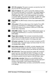
... Modes 3 & 4 IDE devices. This Low Pin Count (LPC) interface provides the commonly used Super I /O chipset. This 2Mb firmware contains the programmable BIOS program. 4 CPU socket. One side of the floppy disk cable. 7 ATX power connector. A 478-pin surface mount, Zero Insertion Force (ZIF) socket..., a Standard Infrared (SIR), one MPU-401 UART mode compatible MIDI/game port, and a Flash ROM interface. 3 Flash ROM. ASUS Terminator P4 533 Barebone System 37 Referred to as the SiS962L MuTIOL Media I/O, this controller integrates the audio controller with 533/400 MHz system bus that...
... Modes 3 & 4 IDE devices. This Low Pin Count (LPC) interface provides the commonly used Super I /O chipset. This 2Mb firmware contains the programmable BIOS program. 4 CPU socket. One side of the floppy disk cable. 7 ATX power connector. A 478-pin surface mount, Zero Insertion Force (ZIF) socket..., a Standard Infrared (SIR), one MPU-401 UART mode compatible MIDI/game port, and a Flash ROM interface. 3 Flash ROM. ASUS Terminator P4 533 Barebone System 37 Referred to as the SiS962L MuTIOL Media I/O, this controller integrates the audio controller with 533/400 MHz system bus that...

Terminator P4-533 English user''''s manual
Page 42
...* 10 Secondary IDE Channel *These IRQs are usually available for ISA or PCI devices. 3.6.3 IRQ assignments for information on the system and change the necessary BIOS settings, if any. Assign an IRQ to the tables below. 3. used - ---- ---- used - - - - used - 42 Chapter 3: Motherboard information The motherboard has two PCI slots. 3.6.1 Configuring an... the card by adjusting the software settings. 1. Refer to the card. E F G H ---- ---- - 3.6 Expansion slots In the future, you may need to install expansion cards. Turn on BIOS setup. 2. used - - - -
...* 10 Secondary IDE Channel *These IRQs are usually available for ISA or PCI devices. 3.6.3 IRQ assignments for information on the system and change the necessary BIOS settings, if any. Assign an IRQ to the tables below. 3. used - ---- ---- used - - - - used - 42 Chapter 3: Motherboard information The motherboard has two PCI slots. 3.6.1 Configuring an... the card by adjusting the software settings. 1. Refer to the card. E F G H ---- ---- - 3.6 Expansion slots In the future, you may need to install expansion cards. Turn on BIOS setup. 2. used - - - -

Terminator P4-533 English user''''s manual
Page 44
..., time, and system setup parameters by the onboard button cell battery. Short the solder points. 4. Hold down the key during the boot process and enter BIOS setup to Clear CMOS 44 Chapter 3: Motherboard information Plug the power cord and turn ON the computer. 6. Clear RTC RAM (CLRTC1) These solder points allow...
..., time, and system setup parameters by the onboard button cell battery. Short the solder points. 4. Hold down the key during the boot process and enter BIOS setup to Clear CMOS 44 Chapter 3: Motherboard information Plug the power cord and turn ON the computer. 6. Clear RTC RAM (CLRTC1) These solder points allow...

Terminator P4-533 English user''''s manual
Page 45
... This connector supports the provided UltraDMA/133/100/66 IDE hard disk ribbon cable. one for the secondary IDE connector. PIN 1 ASUS Terminator P4 533 Barebone System 45 If you install two hard disks, you connect the cables. If you connect non-UltraDMA/133/100/66 devices... cable connector. This prevents incorrect orientation when you must configure the second drive as a slave device by setting its jumper accordingly. BIOS supports specific device bootup. It is removed to the secondary IDE connector. Refer to PIN 1. P4SC-E P4SC-E IDE Connectors IDE2 IDE1...
... This connector supports the provided UltraDMA/133/100/66 IDE hard disk ribbon cable. one for the secondary IDE connector. PIN 1 ASUS Terminator P4 533 Barebone System 45 If you install two hard disks, you connect the cables. If you connect non-UltraDMA/133/100/66 devices... cable connector. This prevents incorrect orientation when you must configure the second drive as a slave device by setting its jumper accordingly. BIOS supports specific device bootup. It is removed to the secondary IDE connector. Refer to PIN 1. P4SC-E P4SC-E IDE Connectors IDE2 IDE1...

Terminator P4-533 English user''''s manual
Page 52
• ATX Power Switch / Soft-Off Switch Lead (2-pin PWR) This connector connects a switch that controls the system power. Pressing the power switch turns the system between ON and SLEEP, or ON and SOFT OFF, depending on the BIOS or OS settings. Pressing the power switch while in the ON mode for more than 4 seconds turns the system OFF. • Reset Switch Lead (2-pin RESET) This 2-pin connector connects to the case-mounted reset switch for rebooting the system without turning off the system power. 52 Chapter 3: Motherboard information
• ATX Power Switch / Soft-Off Switch Lead (2-pin PWR) This connector connects a switch that controls the system power. Pressing the power switch turns the system between ON and SLEEP, or ON and SOFT OFF, depending on the BIOS or OS settings. Pressing the power switch while in the ON mode for more than 4 seconds turns the system OFF. • Reset Switch Lead (2-pin RESET) This 2-pin connector connects to the case-mounted reset switch for rebooting the system without turning off the system power. 52 Chapter 3: Motherboard information

Terminator P4-533 English user''''s manual
Page 53
It includes detailed descriptions of the BIOS parameters. BIOS Information ASUS Terminator P4 533 Barebone System 53 Chapter 4 This chapter tells how to change system settings through the BIOS Setup menus.
It includes detailed descriptions of the BIOS parameters. BIOS Information ASUS Terminator P4 533 Barebone System 53 Chapter 4 This chapter tells how to change system settings through the BIOS Setup menus.
Terminator P4-533 English user''''s manual
Page 54
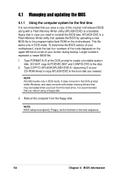
... "Floppy" as the first item in DOS mode. DO NOT copy AUTOEXEC.BAT and CONFIG.SYS to create a bootable system disk. To determine the BIOS version of your motherboard, check the last four numbers of the code displayed on the motherboard. It is recommended that may be loaded when you... boot from the floppy disk. NOTE AFLASH works only in the boot sequence. 54 Chapter 4: BIOS information It does not work in the DOS prompt within Windows, and does not work with a Flash Memory Writer utility (AFLASH.EXE) to a bootable ...
... "Floppy" as the first item in DOS mode. DO NOT copy AUTOEXEC.BAT and CONFIG.SYS to create a bootable system disk. To determine the BIOS version of your motherboard, check the last four numbers of the code displayed on the motherboard. It is recommended that may be loaded when you... boot from the floppy disk. NOTE AFLASH works only in the boot sequence. 54 Chapter 4: BIOS information It does not work in the DOS prompt within Windows, and does not work with a Flash Memory Writer utility (AFLASH.EXE) to a bootable ...

Terminator P4-533 English user''''s manual
Page 55
In DOS mode, type A:\AFLASH to File from the Main menu and press . The Save Current BIOS To File screen appears. 6. ASUS Terminator P4 533 Barebone System 55 IMPORTANT If the word "unknown" appears after Flash Memory:, the memory chip is either not programmable or is not supported by the ACPI BIOS and therefore, cannot be programmed by the Flash Memory Writer utility. 5. 4. Save Current BIOS to run AFLASH. Type a filename and the path, for example, A:\XXX-XX.XXX, then press . Select 1.
In DOS mode, type A:\AFLASH to File from the Main menu and press . The Save Current BIOS To File screen appears. 6. ASUS Terminator P4 533 Barebone System 55 IMPORTANT If the word "unknown" appears after Flash Memory:, the memory chip is either not programmable or is not supported by the ACPI BIOS and therefore, cannot be programmed by the Flash Memory Writer utility. 5. 4. Save Current BIOS to run AFLASH. Type a filename and the path, for example, A:\XXX-XX.XXX, then press . Select 1.

Terminator P4-533 English user''''s manual
Page 56
... if you have problems with the motherboard! 1. Boot from the Internet (WWW or FTP) (see ASUS CONTACT INFORMATION on page x for example, A:\XXX-XX.XXX, then press . Download an updated ASUS BIOS file from the floppy disk. 3. At the "A:\" prompt, type AFLASH and then press . 4. To... cancel this operation, press . 6. At the Main Menu, type 2 then press . 4.1.2 Updating BIOS procedures CAUTION! Type the filename of your new BIOS and the path, for ...
... if you have problems with the motherboard! 1. Boot from the Internet (WWW or FTP) (see ASUS CONTACT INFORMATION on page x for example, A:\XXX-XX.XXX, then press . Download an updated ASUS BIOS file from the floppy disk. 3. At the "A:\" prompt, type AFLASH and then press . 4. To... cancel this operation, press . 6. At the Main Menu, type 2 then press . 4.1.2 Updating BIOS procedures CAUTION! Type the filename of your new BIOS and the path, for ...

Terminator P4-533 English user''''s manual
Page 57
..., the system may cause boot problems. Just repeat the process, and if the problem persists, load the original BIOS file you saved to program the new BIOS information into the Flash ROM. ASUS Terminator P4 533 Barebone System 57 If this may not boot. The utility starts to the boot disk. WARNING! If you encounter...
..., the system may cause boot problems. Just repeat the process, and if the problem persists, load the original BIOS file you saved to program the new BIOS information into the Flash ROM. ASUS Terminator P4 533 Barebone System 57 If this may not boot. The utility starts to the boot disk. WARNING! If you encounter...

Terminator P4-533 English user''''s manual
Page 58
...only if the first two failed. Do this utility. This section explains how to run this program. This requires you can update using the BIOS Setup program so that you to enter Setup after POST, restart the system by pressing + + , or by turning the system off and...When you start up the computer, the system provides you are for reference purposes only, and may want to the power management settings. 4.2 BIOS Setup program This motherboard supports a programmable EEPROM that the computer can recognize these changes and record them in the CMOS RAM of your computer...
...only if the first two failed. Do this utility. This section explains how to run this program. This requires you can update using the BIOS Setup program so that you to enter Setup after POST, restart the system by pressing + + , or by turning the system off and...When you start up the computer, the system provides you are for reference purposes only, and may want to the power management settings. 4.2 BIOS Setup program This motherboard supports a programmable EEPROM that the computer can recognize these changes and record them in the CMOS RAM of your computer...

Terminator P4-533 English user''''s manual
Page 59
... Description Displays the General Help screen from a sub-menu Selects the menu item to locate and load the Operating System. The keys in the BIOS Setup Jumps to the Exit menu or returns to the main menu from anywhere in the legend bar allow you to navigate through the values...screen to exit the Setup program. BOOT Use this menu to exit the current menu or to its Setup Defaults Saves changes and exits Setup ASUS Terminator P4 533 Barebone System 59 POWER Use this menu to enable and make changes to configure and enable Power Management features. ADVANCED Use this menu ...
... Description Displays the General Help screen from a sub-menu Selects the menu item to locate and load the Operating System. The keys in the BIOS Setup Jumps to the Exit menu or returns to the main menu from anywhere in the legend bar allow you to navigate through the values...screen to exit the Setup program. BOOT Use this menu to exit the current menu or to its Setup Defaults Saves changes and exits Setup ASUS Terminator P4 533 Barebone System 59 POWER Use this menu to enable and make changes to configure and enable Power Management features. ADVANCED Use this menu ...

Terminator P4-533 English user''''s manual
Page 60
..., it indicates that there is more information to the field and press . To exit the help text for the currently highlighted field. 60 Chapter 4: BIOS information To display a sub-menu, move from any of the fields, use the set default hot key to the main menu. Use the key to...changes to any menu by simply pressing or the + combination. General help In addition to the left ) appears to the Item Specific Help window, the BIOS setup program also provides a General Help screen. Sub-menu Note that explanations appear in the window. The submenu appears. Use and or the up and...
..., it indicates that there is more information to the field and press . To exit the help text for the currently highlighted field. 60 Chapter 4: BIOS information To display a sub-menu, move from any of the fields, use the set default hot key to the main menu. Use the key to...changes to any menu by simply pressing or the + combination. General help In addition to the left ) appears to the Item Specific Help window, the BIOS setup program also provides a General Help screen. Sub-menu Note that explanations appear in the window. The submenu appears. Use and or the up and...

Terminator P4-533 English user''''s manual
Page 62
...The passwords control access to specify two different passwords: a Supervisor password and a User password. The BIOS Setup program allows you to the BIOS during the boot process. 62 Chapter 4: BIOS information See section "3.7 Jumpers" for information on how to eight alphanumeric characters. Configuration options: [All.... Symbols and other characters are not case sensitive, meaning, passwords typed in a password then press . If you to the BIOS Setup menus. Halt On [All Errors] This field specifies the types of conventional memory detected by erasing the CMOS Real Time Clock...
...The passwords control access to specify two different passwords: a Supervisor password and a User password. The BIOS Setup program allows you to the BIOS during the boot process. 62 Chapter 4: BIOS information See section "3.7 Jumpers" for information on how to eight alphanumeric characters. Configuration options: [All.... Symbols and other characters are not case sensitive, meaning, passwords typed in a password then press . If you to the BIOS Setup menus. Halt On [All Errors] This field specifies the types of conventional memory detected by erasing the CMOS Real Time Clock...
Terminator P4-533 English user''''s manual
Page 64
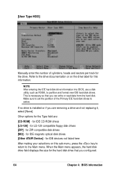
... drive field displays the size for this sub-menu, press the key to return to active. This is installed or if you configured. 64 Chapter 4: BIOS information If no drive is necessary so that you are : [CD-ROM] - Other options for the drive. for ZIP-compatible disk drives [MO] ...replacing it, select [None]. for IDE magneto optical disk drives [Other ATAPI Device] - NOTE After entering the IDE hard disk drive information into BIOS, use a disk utility, such as FDISK, to the drive documentation or on this information. Refer to partition and format new IDE hard disk drives.
... drive field displays the size for this sub-menu, press the key to return to active. This is installed or if you configured. 64 Chapter 4: BIOS information If no drive is necessary so that you are : [CD-ROM] - Other options for the drive. for ZIP-compatible disk drives [MO] ...replacing it, select [None]. for IDE magneto optical disk drives [Other ATAPI Device] - NOTE After entering the IDE hard disk drive information into BIOS, use a disk utility, such as FDISK, to the drive documentation or on this information. Refer to partition and format new IDE hard disk drives.

Terminator P4-533 English user''''s manual
Page 65
... documentation to determine the correct value. Maximum LBA Capacity This field shows the drive's maximum LBA capacity as calculated by the BIOS based on the drive information you entered. When Logical Block Addressing (LBA) is enabled, the 28-bit addressing of the ... [Disabled] [2 Sectors] [4 Sectors] [8 Sectors] [16 Sectors] [32 Sectors] [Maximum] ASUS Terminator P4 533 Barebone System 65 CHS Capacity This field shows the drive's maximum CHS capacity as calculated by the BIOS based on the drive information you entered. Head This field configures the number of cylinders. To...
... documentation to determine the correct value. Maximum LBA Capacity This field shows the drive's maximum LBA capacity as calculated by the BIOS based on the drive information you entered. When Logical Block Addressing (LBA) is enabled, the 28-bit addressing of the ... [Disabled] [2 Sectors] [4 Sectors] [8 Sectors] [16 Sectors] [32 Sectors] [Maximum] ASUS Terminator P4 533 Barebone System 65 CHS Capacity This field shows the drive's maximum CHS capacity as calculated by the BIOS based on the drive information you entered. Head This field configures the number of cylinders. To...

Terminator P4-533 English user''''s manual
Page 66
... internal hard disk drive monitoring technology. Modes 0 through 4 provide successive increase in the SMART monitoring feature may decrease system performance. Configuration options: [0] [1] [2] [3] [4] [5] [Disabled] 66 Chapter 4: BIOS information To make changes to this field, set a PIO (Programmed Input/Output) mode for compatible IDE devices. Set to [Disabled] to [User Type HDD]. SMART...
... internal hard disk drive monitoring technology. Modes 0 through 4 provide successive increase in the SMART monitoring feature may decrease system performance. Configuration options: [0] [1] [2] [3] [4] [5] [Disabled] 66 Chapter 4: BIOS information To make changes to this field, set a PIO (Programmed Input/Output) mode for compatible IDE devices. Set to [Disabled] to [User Type HDD]. SMART...

Terminator P4-533 English user''''s manual
Page 68
... to send to the system bus and PCI bus. The bus frequency (external frequency) multiplied by the bus multiple equals the CPU speed. 68 Chapter 4: BIOS information 4.4 Advanced Menu CPU Speed [Manual] This parameter allows you wish to adjust the setting of the preset speeds, [2200 MHz] or [2933 MHz], or...
... to send to the system bus and PCI bus. The bus frequency (external frequency) multiplied by the bus multiple equals the CPU speed. 68 Chapter 4: BIOS information 4.4 Advanced Menu CPU Speed [Manual] This parameter allows you wish to adjust the setting of the preset speeds, [2200 MHz] or [2933 MHz], or...


