
Terminator P4-533 English user''''s manual
Page 3
Features Table of contents Disclaimer/Copyrights 2 FCC/CDC statements 5 Safety information 6 About this guide 7 ASUS contact information 9 System package contents 10 Chapter 1: System Introduction 11 1.1 Front Panel Features 12 1.2 Rear Panel Features 13 1.3 ...connect cables 29 2.9.1 Front panel 29 2.9.2 UAEX and card reader modules 30 2.10 Replace the cover 31 2.11 Connect External Devices 33 2.12 Power Supply Specifications 34 2.12.1 Input Characteristics 34 2.12.2 Output Characteristics 34 2.12.3 Over-Voltage Protection (OVP 34 Chapter 3: Motherboard Information 35 3.1...
Features Table of contents Disclaimer/Copyrights 2 FCC/CDC statements 5 Safety information 6 About this guide 7 ASUS contact information 9 System package contents 10 Chapter 1: System Introduction 11 1.1 Front Panel Features 12 1.2 Rear Panel Features 13 1.3 ...connect cables 29 2.9.1 Front panel 29 2.9.2 UAEX and card reader modules 30 2.10 Replace the cover 31 2.11 Connect External Devices 33 2.12 Power Supply Specifications 34 2.12.1 Input Characteristics 34 2.12.2 Output Characteristics 34 2.12.3 Over-Voltage Protection (OVP 34 Chapter 3: Motherboard Information 35 3.1...

Terminator P4-533 English user''''s manual
Page 4
... 4.3 Main Menu 61 4.3.1 Primary and Secondary Master/Slave 63 4.3.2 Keyboard Features 67 4.4 Advanced Menu 68 4.4.1 Chip Configuration 70 4.4.2 I/O Device Configuration 72 4.4.3 PCI Configuration 74 4.5 Power Menu 77 4.5.1 Power Up Control 79 4.5.2 Hardware Monitor 81 4.6 Boot Menu 83 4.7 Exit Menu 85 Chapter 5: Starting up 89 5.1 Install an operating system 90 5.2 Support CD information...
... 4.3 Main Menu 61 4.3.1 Primary and Secondary Master/Slave 63 4.3.2 Keyboard Features 67 4.4 Advanced Menu 68 4.4.1 Chip Configuration 70 4.4.2 I/O Device Configuration 72 4.4.3 PCI Configuration 74 4.5 Power Menu 77 4.5.1 Power Up Control 79 4.5.2 Hardware Monitor 81 4.6 Boot Menu 83 4.7 Exit Menu 85 Chapter 5: Starting up 89 5.1 Install an operating system 90 5.2 Support CD information...

Terminator P4-533 English user''''s manual
Page 6
...the product on a stable surface. • If you encounter technical problems with the package. • Before using the product, make sure all power cables are using an adapter or extension cord. These devices could interrupt the grounding circuit. • Make sure that all cables are correctly connected and... the power cables are not sure about the voltage of the electrical outlet you detect any area where it by yourself. If you are not ...
...the product on a stable surface. • If you encounter technical problems with the package. • Before using the product, make sure all power cables are using an adapter or extension cord. These devices could interrupt the grounding circuit. • Make sure that all cables are correctly connected and... the power cables are not sure about the voltage of the electrical outlet you detect any area where it by yourself. If you are not ...

Terminator P4-533 English user''''s manual
Page 7
Chapter 1: System Introduction This chapter gives a general description of the BIOS parameters. 5. Chapter 3: Motherboard Information This chapter gives information about the ASUS Terminator P4 533 Barebone System. Chapter 5: Starting up This chapter helps you power up your system and install drivers and utilities that came with the support CD. 7 It also includes information on the USB...
Chapter 1: System Introduction This chapter gives a general description of the BIOS parameters. 5. Chapter 3: Motherboard Information This chapter gives information about the ASUS Terminator P4 533 Barebone System. Chapter 5: Starting up This chapter helps you power up your system and install drivers and utilities that came with the support CD. 7 It also includes information on the USB...

Terminator P4-533 English user''''s manual
Page 10
... the components before starting. Motherboard 3. CD-ROM Drive (optional) 6. 56K PCI modem card (optional) 7. User's guide NOTE Optional items may not be present in your ASUS Terminator P4 533 pacakge for the following items: 1. Barebone system 2. Switching power supply 4. 1.44MB floppy disk drive 5. Support CD 8. IMPORTANT If you need them. 10
... the components before starting. Motherboard 3. CD-ROM Drive (optional) 6. 56K PCI modem card (optional) 7. User's guide NOTE Optional items may not be present in your ASUS Terminator P4 533 pacakge for the following items: 1. Barebone system 2. Switching power supply 4. 1.44MB floppy disk drive 5. Support CD 8. IMPORTANT If you need them. 10

Terminator P4-533 English user''''s manual
Page 12
...Open chassis 2 I /O door by flipping up the door. 1.1 Front Panel Features The ASUS Terminator P4 533 barebone system is a door that covers accessible I/O features including a CF card reader (or a 4-in the ASUS TriOptix form factor chassis. NOTE On request, the optional 4-in-1 card reader may vary ... Introduction NOTE The CD-ROM drive and modem card are optional items. Chassis 1 Chassis 2 CD-ROM Drive (optional) Floppy Drive Power Button Power LED HDD LED Headphone Jack Card reader Microphone Jack USB 2.0 Ports Card reader Headphone Jack USB 2.0 Ports Microphone Jack Front Panel I/O...
...Open chassis 2 I /O door by flipping up the door. 1.1 Front Panel Features The ASUS Terminator P4 533 barebone system is a door that covers accessible I/O features including a CF card reader (or a 4-in the ASUS TriOptix form factor chassis. NOTE On request, the optional 4-in-1 card reader may vary ... Introduction NOTE The CD-ROM drive and modem card are optional items. Chassis 1 Chassis 2 CD-ROM Drive (optional) Floppy Drive Power Button Power LED HDD LED Headphone Jack Card reader Microphone Jack USB 2.0 Ports Card reader Headphone Jack USB 2.0 Ports Microphone Jack Front Panel I/O...
Terminator P4-533 English user''''s manual
Page 13
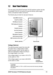
... the switch to 115V in your area. 1.2 Rear Panel Features The rear panel of the ASUS Terminator P4 533 barebone system includes the standard PC99 I/O connectors for external devices, power supply socket, and optional modem connectors. Use this switch to select the appropriate voltage according to... the voltage supply in your area is 200-240V, set the switch to 115V. ASUS Terminator P4 533 Barebone System 13 If the voltage ...
... the switch to 115V in your area. 1.2 Rear Panel Features The rear panel of the ASUS Terminator P4 533 barebone system includes the standard PC99 I/O connectors for external devices, power supply socket, and optional modem connectors. Use this switch to select the appropriate voltage according to... the voltage supply in your area is 200-240V, set the switch to 115V. ASUS Terminator P4 533 Barebone System 13 If the voltage ...

Terminator P4-533 English user''''s manual
Page 14
You will see here the standard components that come already installed in the system and the places where you remove the cover and flip out the drive frame. Game/MIDI/COM1 Extension Module Two 5.25" 3.5" HDD Drive Bays Drive Bay 3.5" Floppy Drive Modem Card (optional) Motherboard USB/audio Board Power Supply 14 Chapter 1: System Introduction 1.3 Internal Features The figure below shows the internal view of the system when you can install the other required components to get the system running.
You will see here the standard components that come already installed in the system and the places where you remove the cover and flip out the drive frame. Game/MIDI/COM1 Extension Module Two 5.25" 3.5" HDD Drive Bays Drive Bay 3.5" Floppy Drive Modem Card (optional) Motherboard USB/audio Board Power Supply 14 Chapter 1: System Introduction 1.3 Internal Features The figure below shows the internal view of the system when you can install the other required components to get the system running.
Terminator P4-533 English user''''s manual
Page 17
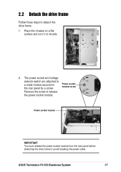
ASUS Terminator P4 533 Barebone System 17 Power socket module IMPORTANT You must release the power socket module from the rear panel before detaching the drive frame to the rear panel by a screw. The power socket and voltage selector switch are attached to a metal module secured to avoid breaking the power cable. Power socket module screw Remove the screw to detach the drive frame. 1. Place the chassis on a flat surface and turn it on its side. 2. 2.2 Detach the drive frame Follow these steps to release the power socket module.
ASUS Terminator P4 533 Barebone System 17 Power socket module IMPORTANT You must release the power socket module from the rear panel before detaching the drive frame to the rear panel by a screw. The power socket and voltage selector switch are attached to a metal module secured to avoid breaking the power cable. Power socket module screw Remove the screw to detach the drive frame. 1. Place the chassis on a flat surface and turn it on its side. 2. 2.2 Detach the drive frame Follow these steps to release the power socket module.

Terminator P4-533 English user''''s manual
Page 18
Place your thumb on the right edge of the power socket module, then slide the module to the right until it outward. Drive frame Swivel edge NOTE The drive frame has a swivel (hinge-like) edge that is not necessary to the main chassis. It is attached to completely detach the drive frame from the rear panel. 4. Carefully lay the drive frame alongside the main chassis frame. 18 Chapter 2: Basic Installation Unlatch the drive frame by pulling it is completely detached from the chassis when installing components. 5. 3.
Place your thumb on the right edge of the power socket module, then slide the module to the right until it outward. Drive frame Swivel edge NOTE The drive frame has a swivel (hinge-like) edge that is not necessary to the main chassis. It is attached to completely detach the drive frame from the rear panel. 4. Carefully lay the drive frame alongside the main chassis frame. 18 Chapter 2: Basic Installation Unlatch the drive frame by pulling it is completely detached from the chassis when installing components. 5. 3.
Terminator P4-533 English user''''s manual
Page 25
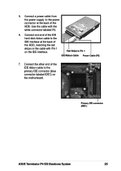
Primary IDE connector (IDE1) ASUS Terminator P4 533 Barebone System 25 Use the cable with Pin 1 on the IDE interface. Connect the other end of the HDD. 5. Connect one end of the IDE hard disk ribbon cable to the IDE interface at the back of the IDE ribbon cable to the primary IDE connector (blue connector labeled IDE1) on the cable with the white connector labeled P3. 6. Connect a power cable from the power supply to Pin 1 IDE Ribbon Cable Power Cable (P3) 7. Red Stripe to the power connector at the back of the HDD, matching the red stripe on the motherboard.
Primary IDE connector (IDE1) ASUS Terminator P4 533 Barebone System 25 Use the cable with Pin 1 on the IDE interface. Connect the other end of the HDD. 5. Connect one end of the IDE hard disk ribbon cable to the IDE interface at the back of the IDE ribbon cable to the primary IDE connector (blue connector labeled IDE1) on the cable with the white connector labeled P3. 6. Connect a power cable from the power supply to Pin 1 IDE Ribbon Cable Power Cable (P3) 7. Red Stripe to the power connector at the back of the HDD, matching the red stripe on the motherboard.

Terminator P4-533 English user''''s manual
Page 27
...5. Connect the other end of the CD-ROM, matching the red stripe on the cable with the white connector labeled P1. 6. Connect a power cable from the power supply to the power connector at the back of the IDE ribbon cable to the black 4-pin connector labeled CD on the motherboard. Connect one end... the 4-pin connector at the back of Red Stripe to the IDE interface at the back of the IDE ribbon cable to Pin 1 Power Cable (P1) the CD-ROM. 8. Connect one end of the CD-ROM. Secondary IDE connector (IDE2) CD-ROM Connector (CD1) ASUS Terminator P4 533 Barebone System 27
...5. Connect the other end of the CD-ROM, matching the red stripe on the cable with the white connector labeled P1. 6. Connect a power cable from the power supply to the power connector at the back of the IDE ribbon cable to the black 4-pin connector labeled CD on the motherboard. Connect one end... the 4-pin connector at the back of Red Stripe to the IDE interface at the back of the IDE ribbon cable to Pin 1 Power Cable (P1) the CD-ROM. 8. Connect one end of the CD-ROM. Secondary IDE connector (IDE2) CD-ROM Connector (CD1) ASUS Terminator P4 533 Barebone System 27

Terminator P4-533 English user''''s manual
Page 29
...connect these cables before you were installing components. ASUS Terminator P4 533 Barebone System 29 2.9 Re-connect cables You may have disconnected some cables when you replace the chassis cover. 2.9.1 LED cables Power Switch Power LED HDD LED PANEL1 Connector Power LED Speaker Connector +5VSB PLED +5V Ground ... ExtSMI# Ground PWR Ground Reset Ground PANEL1 IDE_LED1 Message LED SMI Lead Reset SW ATX Power Switch* * Requires an ATX power supply. • Connect the power switch and power LED cables to their respective leads in the PANEL1 connector on the motherboard. • ...
...connect these cables before you were installing components. ASUS Terminator P4 533 Barebone System 29 2.9 Re-connect cables You may have disconnected some cables when you replace the chassis cover. 2.9.1 LED cables Power Switch Power LED HDD LED PANEL1 Connector Power LED Speaker Connector +5VSB PLED +5V Ground ... ExtSMI# Ground PWR Ground Reset Ground PANEL1 IDE_LED1 Message LED SMI Lead Reset SW ATX Power Switch* * Requires an ATX power supply. • Connect the power switch and power LED cables to their respective leads in the PANEL1 connector on the motherboard. • ...

Terminator P4-533 English user''''s manual
Page 34
...-p 120mVp-p 120mVp-p 50mVp-p 50mVp-p 2.12.3 Over-Voltage Protection (OVP) Output Voltage +5V +12V +3.3V Maximum Voltage 6.5V 15.6V 4.3V NOTE The power supply will shut down or automatically recover when the fault condition is removed 34 Chapter 2: Basic Installation at 25°C 70% min. 2.12... Power Supply Specifications 2.12.1 Input Characteristics Input Voltage Range Range 1 Range 2 Input Frequency Range Maximum Input ac Current Inrush Current Efficiency...
...-p 120mVp-p 120mVp-p 50mVp-p 50mVp-p 2.12.3 Over-Voltage Protection (OVP) Output Voltage +5V +12V +3.3V Maximum Voltage 6.5V 15.6V 4.3V NOTE The power supply will shut down or automatically recover when the fault condition is removed 34 Chapter 2: Basic Installation at 25°C 70% min. 2.12... Power Supply Specifications 2.12.1 Input Characteristics Input Voltage Range Range 1 Range 2 Input Frequency Range Maximum Input ac Current Inrush Current Efficiency...
Terminator P4-533 English user''''s manual
Page 37
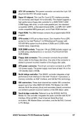
... MHz system bus that allows 4.3GB/s and 3.2GB/s data transfer rates, respectively. 5 DDR DIMM sockets. ASUS Terminator P4 533 Barebone System 37 This power connector connects the 4-pin 12V plug from the ATX 12V power supply. 2 Super I /O functionality. This 2Mb firmware contains the programmable BIOS program. 4 CPU socket. These two 184-... cable. 10 South bridge controller. This 20-pin connector connects to prevent incorrect insertion of the floppy disk cable. 7 ATX power connector. One side of the connector is slotted to four Ultra DMA133/100/66, PIO Modes 3 & 4 IDE devices. The...
... MHz system bus that allows 4.3GB/s and 3.2GB/s data transfer rates, respectively. 5 DDR DIMM sockets. ASUS Terminator P4 533 Barebone System 37 This power connector connects the 4-pin 12V plug from the ATX 12V power supply. 2 Super I /O functionality. This 2Mb firmware contains the programmable BIOS program. 4 CPU socket. These two 184-... cable. 10 South bridge controller. This 20-pin connector connects to prevent incorrect insertion of the floppy disk cable. 7 ATX power connector. One side of the connector is slotted to four Ultra DMA133/100/66, PIO Modes 3 & 4 IDE devices. The...
Terminator P4-533 English user''''s manual
Page 43
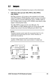
..., DRAM in slow refresh, power supply in reduced power mode). Otherwise, the system does not power up from S1 sleep mode (CPU stopped, DRAM refreshed, system running in sleep mode. P4SC-E ® P4SC-E USB Device Wake Up USB_PWR12 1 2 2 3 +5V +5VSB (Default) USB_PWR34 USB_PWR56 12 23 +5V +5VSB (Default) ASUS Terminator P4 533 Barebone System 43 USB device...
..., DRAM in slow refresh, power supply in reduced power mode). Otherwise, the system does not power up from S1 sleep mode (CPU stopped, DRAM refreshed, system running in sleep mode. P4SC-E ® P4SC-E USB Device Wake Up USB_PWR12 1 2 2 3 +5V +5VSB (Default) USB_PWR34 USB_PWR56 12 23 +5V +5VSB (Default) ASUS Terminator P4 533 Barebone System 43 USB device...

Terminator P4-533 English user''''s manual
Page 44
.... 2. The RAM data in CMOS. Remove the battery. 3. Re-install the battery. 5. Plug the power cord and turn ON the computer. 6. P4SC-E ® P4SC-E Clear RTC RAM CR2032 3V Lithium Cell CMOS Power CLRTC1 Short solder points to clear the Real Time Clock (RTC) RAM in CMOS, that include system setup ...information such as system passwords, is powered by erasing the CMOS RTC RAM data. You can clear the CMOS memory of date, time, and system setup parameters by the onboard button cell...
.... 2. The RAM data in CMOS. Remove the battery. 3. Re-install the battery. 5. Plug the power cord and turn ON the computer. 6. P4SC-E ® P4SC-E Clear RTC RAM CR2032 3V Lithium Cell CMOS Power CLRTC1 Short solder points to clear the Real Time Clock (RTC) RAM in CMOS, that include system setup ...information such as system passwords, is powered by erasing the CMOS RTC RAM data. You can clear the CMOS memory of date, time, and system setup parameters by the onboard button cell...

Terminator P4-533 English user''''s manual
Page 46
... IDE connector cause this LED to the hard disk activity LED. P4SC-E Floppy Disk Drive Connector 3. Hard disk activity LED (2-pin IDE_LED1) This connector supplies power to light up. P4SC-E ® P4SC-E IDE Activity LED TIP: If the case-mounted LED does not light, try reversing the 2-pin plug. IDE_LED1 46...
... IDE connector cause this LED to the hard disk activity LED. P4SC-E Floppy Disk Drive Connector 3. Hard disk activity LED (2-pin IDE_LED1) This connector supplies power to light up. P4SC-E ® P4SC-E IDE Activity LED TIP: If the case-mounted LED does not light, try reversing the 2-pin plug. IDE_LED1 46...

Terminator P4-533 English user''''s manual
Page 47
...on the +5-volt standby lead (+5VSB). The system may become unstable and may experience difficulty powering up if the power supply is 230W, or 300W for a fully configured system. ATX power connectors (20-pin ATXPWR, 4-pin ATX +12V) These connectors connect to the CPU.... ATX Power Connector COM +12V DC IMPORTANT If you connect the 4-pin ATX +12V power plug to provide sufficient power to an ATX 12V power supply. Find the proper orientation and push down firmly until the connectors completely fit. 4. The minimum recommended wattage is inadequate. ASUS Terminator P4 533 Barebone ...
...on the +5-volt standby lead (+5VSB). The system may become unstable and may experience difficulty powering up if the power supply is 230W, or 300W for a fully configured system. ATX power connectors (20-pin ATXPWR, 4-pin ATX +12V) These connectors connect to the CPU.... ATX Power Connector COM +12V DC IMPORTANT If you connect the 4-pin ATX +12V power plug to provide sufficient power to an ATX 12V power supply. Find the proper orientation and push down firmly until the connectors completely fit. 4. The minimum recommended wattage is inadequate. ASUS Terminator P4 533 Barebone ...

Terminator P4-533 English user''''s manual
Page 48
... Do not forget to connect the fan cables to the ground pin. DO NOT place jumper caps on the fan manufacturer. CPU, Chassis, and Power Fan Connectors (3-pin CPU_FAN1, CHA_FAN1) The three fan connectors support cooling fans of 350mA (4.2 Watts) or a total of the expansion slots. The fan wiring and ...
... Do not forget to connect the fan cables to the ground pin. DO NOT place jumper caps on the fan manufacturer. CPU, Chassis, and Power Fan Connectors (3-pin CPU_FAN1, CHA_FAN1) The three fan connectors support cooling fans of 350mA (4.2 Watts) or a total of the expansion slots. The fan wiring and ...


