

User Guide
Page 4
... 3: Motherboard Information 3.1 Motherboard layout 3-2 3.2 Jumpers...3-4 3.3 Internal connectors 3-7 Chapter 4: BIOS setup 4.1 Managing and updating your BIOS 4-2 4.1.1 ASUS CrashFree BIOS 3 utility 4-2 4.1.2 ASUS EzFlash Utility 4-3 4.1.3 BUPDATER utility 4-4 4.2 BIOS setup program 4-6 4.2.1 BIOS menu screen 4-7 4.2.2 Menu bar 4-7 4.2.3 Menu items 4-8 4.2.4...21 4.4.9 WHEA Support 4-22 4.4.10 NCT6779D Super IO Configuration 4-22 4.4.11 Intel Server Platform Services 4-23 4.4.12 Onboard LAN Configuration 4-24 4.4.13 MIO Card Configuration 4-24 4.4.14 Serial Port Console Redirection ...
... 3: Motherboard Information 3.1 Motherboard layout 3-2 3.2 Jumpers...3-4 3.3 Internal connectors 3-7 Chapter 4: BIOS setup 4.1 Managing and updating your BIOS 4-2 4.1.1 ASUS CrashFree BIOS 3 utility 4-2 4.1.2 ASUS EzFlash Utility 4-3 4.1.3 BUPDATER utility 4-4 4.2 BIOS setup program 4-6 4.2.1 BIOS menu screen 4-7 4.2.2 Menu bar 4-7 4.2.3 Menu items 4-8 4.2.4...21 4.4.9 WHEA Support 4-22 4.4.10 NCT6779D Super IO Configuration 4-22 4.4.11 Intel Server Platform Services 4-23 4.4.12 Onboard LAN Configuration 4-24 4.4.13 MIO Card Configuration 4-24 4.4.14 Serial Port Console Redirection ...

User Guide
Page 8
...same or equivalent type recommended by trained service personnel only. • Before operating the server, carefully read all the manuals included with the server package. • Before using the server, make sure all power cables from the existing system before you service. • If...is broken, do not try to the manufacturer's instructions. If any additional devices to avoid electrical shock. This server system is incorrectly replaced. Place the server on a stable surface. Dispose of explosion if battery is heavy. Lithium-Ion Battery Warning CAUTION! viii Safety information...
...same or equivalent type recommended by trained service personnel only. • Before operating the server, carefully read all the manuals included with the server package. • Before using the server, make sure all power cables from the existing system before you service. • If...is broken, do not try to the manufacturer's instructions. If any additional devices to avoid electrical shock. This server system is incorrectly replaced. Place the server on a stable surface. Dispose of explosion if battery is heavy. Lithium-Ion Battery Warning CAUTION! viii Safety information...

User Guide
Page 10
...is intended for different system components. Chapter 3: Motherboard information This chapter includes the motherboard layout and brief descriptions of configuring a server. x Chapter 2: Hardware setup This chapter lists the hardware setup procedures that you have to change system settings through the ...BIOS Setup menus and describes the BIOS parameters. 5. Chapter 1: Product Introduction This chapter describes the general features of the server, including sections on front panel and rear panel specifications. 2. Chapter 4: BIOS information This chapter tells how to perform when...
...is intended for different system components. Chapter 3: Motherboard information This chapter includes the motherboard layout and brief descriptions of configuring a server. x Chapter 2: Hardware setup This chapter lists the hardware setup procedures that you have to change system settings through the ...BIOS Setup menus and describes the BIOS parameters. 5. Chapter 1: Product Introduction This chapter describes the general features of the server, including sections on front panel and rear panel specifications. 2. Chapter 4: BIOS information This chapter tells how to perform when...

User Guide
Page 11
... and additional information to emphasize a word or a phrase. Refer to set up and use the proprietary ASUS server management utility. 2. Conventions used in this manual. ASUS Server Web-based Management (ASWM) user guide This manual tells how to the ASUS contact information. xi Typography Bold text Italics Indicates a menu or an item to complete a task...
... and additional information to emphasize a word or a phrase. Refer to set up and use the proprietary ASUS server management utility. 2. Conventions used in this manual. ASUS Server Web-based Management (ASWM) user guide This manual tells how to the ASUS contact information. xi Typography Bold text Italics Indicates a menu or an item to complete a task...

User Guide
Page 13
Chapter 1: Product Introduction Product introduction This chapter describes the general features of the server, including sections on front panel and rear panel specifications. 1
Chapter 1: Product Introduction Product introduction This chapter describes the general features of the server, including sections on front panel and rear panel specifications. 1

User Guide
Page 14
... package contents Check your system package for the following items. Model Name TS110-E8-PI4 Chassis ASUS T11 Pedestal Chassis Motherboard ASUS P9D-X/MR Server Board Component 1 x 300W Single Power Supply 1 x 120 mm x 120 mm System fan 4 x SATA Cables 1 x Front I/O Board Accessories 1 x TS110-E8-PI4 User's Guide 1 x TS110-E8-PI4 Support CD 1 x Bag of Screws 1 x AC Power Cable Optional Items CPU Heatsink...
... package contents Check your system package for the following items. Model Name TS110-E8-PI4 Chassis ASUS T11 Pedestal Chassis Motherboard ASUS P9D-X/MR Server Board Component 1 x 300W Single Power Supply 1 x 120 mm x 120 mm System fan 4 x SATA Cables 1 x Front I/O Board Accessories 1 x TS110-E8-PI4 User's Guide 1 x TS110-E8-PI4 Support CD 1 x Bag of Screws 1 x AC Power Cable Optional Items CPU Heatsink...
User Guide
Page 15
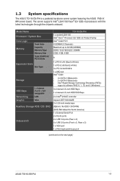
... Type Storage HDD Bays Networking Graphic I = internal A or S = hotswappable LAN VGA Auxiliary Storage FDD / CD / DVD Onboard I/O TS110-E8-PI4 1 x socket LGA1150 Intel® Xeon® Processor E3-1200 v3 Product Family Intel® C222 PCH 4 UDIMM (2 Channels) Maximum ...3.0 ports (Rear x 2) 4 x USB 2.0 ports (Front x 2, Rear x 2) 1 x VGA port 1 x PS/2 keyboard/mouse port (continued on the next page) ASUS TS110-E8-PI4 1-3 The server supports Intel® LGA1150 Xeon® E3-1200 v3 processors with the latest technologies through the chipsets onboard. 1.3 System specifications The...
... Type Storage HDD Bays Networking Graphic I = internal A or S = hotswappable LAN VGA Auxiliary Storage FDD / CD / DVD Onboard I/O TS110-E8-PI4 1 x socket LGA1150 Intel® Xeon® Processor E3-1200 v3 Product Family Intel® C222 PCH 4 UDIMM (2 Channels) Maximum ...3.0 ports (Rear x 2) 4 x USB 2.0 ports (Front x 2, Rear x 2) 1 x VGA port 1 x PS/2 keyboard/mouse port (continued on the next page) ASUS TS110-E8-PI4 1-3 The server supports Intel® LGA1150 Xeon® E3-1200 v3 processors with the latest technologies through the chipsets onboard. 1.3 System specifications The...

User Guide
Page 16
System specifications OS Support Windows® Server 2008 R2 Windows® Server 2012 Windows® Server 2012 R2 RedHat® Enterprise Linux SuSE® Linux Enterprise Server CentOS VMware Citrix XenServer * Visit http://www.asus.com/ for the latest OS support. Anti-virus Software Management Solution Software Dimension (HH x WW x DD) Net Weight Kg (CPU, DRAM...
System specifications OS Support Windows® Server 2008 R2 Windows® Server 2012 Windows® Server 2012 R2 RedHat® Enterprise Linux SuSE® Linux Enterprise Server CentOS VMware Citrix XenServer * Visit http://www.asus.com/ for the latest OS support. Anti-virus Software Management Solution Software Dimension (HH x WW x DD) Net Weight Kg (CPU, DRAM...
User Guide
Page 17
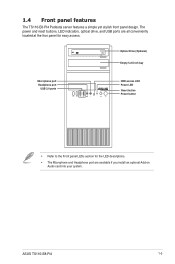
... port USB 2.0 ports HDD access LED Power LED Reset button Power button • Refer to the Front panel LEDs section for easy access. ASUS TS110-E8-PI4 1-5 1.4 Front panel features The TS110-E8-PI4 Pedestal server features a simple yet stylish front panel design. The power and reset buttons, LED indicators, optical drive, and USB ports are all conveniently...
... port USB 2.0 ports HDD access LED Power LED Reset button Power button • Refer to the Front panel LEDs section for easy access. ASUS TS110-E8-PI4 1-5 1.4 Front panel features The TS110-E8-PI4 Pedestal server features a simple yet stylish front panel design. The power and reset buttons, LED indicators, optical drive, and USB ports are all conveniently...

User Guide
Page 19
Power supply unit 2. 120 mm x 120 mm system fan 3. ASUS P9D-X/MR Server Board 4. Optical drive (Optional) 6. 1 x 5.25-inch drive bay 7. Front I/O board (hidden) 8. 3 x 3.5-inch Internal HDD bays 9. 1 x 2.5-inch Internal HDD/SSD bay Turn ...on the front or rear panel. *WARNING HAZARDOUS MOVING PARTS KEEP FINGERS AND OTHER BODY PARTS AWAY ASUS TS110-E8-PI4 1-7 Expansion card locks 5. The barebone server does not include a floppy disk drive. 1.6 Internal features The TS110-E8-PI4 Pedestal server sytem includes the basic components as shown: 1. If you need to use a floppy disk, ...
Power supply unit 2. 120 mm x 120 mm system fan 3. ASUS P9D-X/MR Server Board 4. Optical drive (Optional) 6. 1 x 5.25-inch drive bay 7. Front I/O board (hidden) 8. 3 x 3.5-inch Internal HDD bays 9. 1 x 2.5-inch Internal HDD/SSD bay Turn ...on the front or rear panel. *WARNING HAZARDOUS MOVING PARTS KEEP FINGERS AND OTHER BODY PARTS AWAY ASUS TS110-E8-PI4 1-7 Expansion card locks 5. The barebone server does not include a floppy disk drive. 1.6 Internal features The TS110-E8-PI4 Pedestal server sytem includes the basic components as shown: 1. If you need to use a floppy disk, ...

User Guide
Page 22
... inside the chassis that can cause injury, such as the CPU fan, rear fan, and other sharp-edged parts. • The images of the barebone server shown in this section are for reference purposes only and may not exactly match the model you unplug the power cord before removing the side...
... inside the chassis that can cause injury, such as the CPU fan, rear fan, and other sharp-edged parts. • The images of the barebone server shown in this section are for reference purposes only and may not exactly match the model you unplug the power cord before removing the side...

User Guide
Page 34
... 4. Locate the HDD cage lock, press the it up (A), then swing the HDD cage outwards (B) until it clicks in place. 2.6 Hard disk drives (HDD) The server system supports three (3) 3.5-inch Serial ATA hard disk drives via the hard disk drive bays and one 2.5-inch HDD/SSD drive at the bottom of...
... 4. Locate the HDD cage lock, press the it up (A), then swing the HDD cage outwards (B) until it clicks in place. 2.6 Hard disk drives (HDD) The server system supports three (3) 3.5-inch Serial ATA hard disk drives via the hard disk drive bays and one 2.5-inch HDD/SSD drive at the bottom of...

User Guide
Page 80
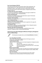
... Error ME NM FW Status Value : 0x80000001 BIOS Booting Mode : Power Optimized Mode Cores Disabled : 0 ME FW SKU Information : Node Manager End-of the Intel Server Platform Services configured in the system. IRQ=5] [IO=378h: IRQ=5, 6, 7, 10, 11, 12] [IO=278h; IRQ=5, 6, 7, 10, 11, 12] [IO=3BCh;...Mode] [EPP-1.9 and SPP Mode] [EPP-1.7 and SPP Mode] [ECP Mode] [ECP and EPP 1.9 Mode] [ECP and EPP 1.7 Mode] 4.4.11 Intel Server Platform Services This item displays the information of -POST Status : EOP disabled in POST 4-24 Chapter 4: BIOS setup Parallel Port [Enabled] Allows you to set...
... Error ME NM FW Status Value : 0x80000001 BIOS Booting Mode : Power Optimized Mode Cores Disabled : 0 ME FW SKU Information : Node Manager End-of the Intel Server Platform Services configured in the system. IRQ=5] [IO=378h: IRQ=5, 6, 7, 10, 11, 12] [IO=278h; IRQ=5, 6, 7, 10, 11, 12] [IO=3BCh;...Mode] [EPP-1.9 and SPP Mode] [EPP-1.7 and SPP Mode] [ECP Mode] [ECP and EPP 1.9 Mode] [ECP and EPP 1.7 Mode] 4.4.11 Intel Server Platform Services This item displays the information of -POST Status : EOP disabled in POST 4-24 Chapter 4: BIOS setup Parallel Port [Enabled] Allows you to set...
User Guide
Page 83
...] [115200] Flow Control [None] Allows you to specify if Bootloader is selected than Legacy console redirection. Configuration options: [None] [Hardware RTS/CTS] [Software Xon/Xoff] ASUS TS110-E8-PI4 4-27 Flow Control [Hardware RTS/CTS] Flow control can be sent to re-start the flow. Long or noisy lines may require lower speeds. Configuration... [Enabled] This allows you set Bits per second [115200] Selects serial port transmission speed. Configuration options: [Always Enable] [Bootloader] Serial Port for Out-of a Windows Server OS through a serial port.
...] [115200] Flow Control [None] Allows you to specify if Bootloader is selected than Legacy console redirection. Configuration options: [None] [Hardware RTS/CTS] [Software Xon/Xoff] ASUS TS110-E8-PI4 4-27 Flow Control [Hardware RTS/CTS] Flow control can be sent to re-start the flow. Long or noisy lines may require lower speeds. Configuration... [Enabled] This allows you set Bits per second [115200] Selects serial port transmission speed. Configuration options: [Always Enable] [Bootloader] Serial Port for Out-of a Windows Server OS through a serial port.

User Guide
Page 102
... arrow keys to use and press . From the following are typical values: RAID 0: 128KB RAID 10: 64KB RAID 5: 64KB We recommend a lower stripe size for server systems, and a higher stripe size for multimedia computer systems used mainly for RAID 0, 10 and 5 only) then press . WARNING: ALL DATA ON SELECTED DISKS WILL...
... arrow keys to use and press . From the following are typical values: RAID 0: 128KB RAID 10: 64KB RAID 5: 64KB We recommend a lower stripe size for server systems, and a higher stripe size for multimedia computer systems used mainly for RAID 0, 10 and 5 only) then press . WARNING: ALL DATA ON SELECTED DISKS WILL...
User Guide
Page 111
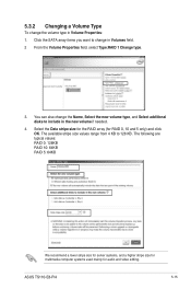
Select the Data stripe size for the RAID array (for audio and video editing. ASUS TS110-E8-PI4 5-15 5.3.2 Changing a Volume Type To change the volume type in the new volume if needed. 4. You can also change in Volumes field. 2 From the Volume ... from 4 KB to include in Volume Properties: 1. The following are typical values: RAID 0: 128KB RAID 10: 64KB RAID 5: 64KB We recommend a lower stripe size for server systems, and a higher stripe size for multimedia computer systems used mainly for RAID 0, 10 and 5 only) and click OK.
Select the Data stripe size for the RAID array (for audio and video editing. ASUS TS110-E8-PI4 5-15 5.3.2 Changing a Volume Type To change the volume type in the new volume if needed. 4. You can also change in Volumes field. 2 From the Volume ... from 4 KB to include in Volume Properties: 1. The following are typical values: RAID 0: 128KB RAID 10: 64KB RAID 5: 64KB We recommend a lower stripe size for server systems, and a higher stripe size for multimedia computer systems used mainly for RAID 0, 10 and 5 only) and click OK.

User Guide
Page 116
... driver disk The system does not include a floppy drive. Enter the BIOS Setup. 4. C22x INTEL RAID Driver Windows 32 bit(AHCI / AHCI RAID) Windows Server 2012 64 bit (AHCI / AHCI RAID) Back Exit 6-2 Chapter 6: Driver installation A floppy disk with the RAID driver is included in the optical drive. ...Write DMI FreeDOS command prompt 7. Exit the BIOS Setup and restart your computer. 6.1 RAID driver installation After creating the RAID sets for your server system, you are now ready to install an operating system to the sub-menu. From the C22x Intel RAID Driver sub-menu, use a...
... driver disk The system does not include a floppy drive. Enter the BIOS Setup. 4. C22x INTEL RAID Driver Windows 32 bit(AHCI / AHCI RAID) Windows Server 2012 64 bit (AHCI / AHCI RAID) Back Exit 6-2 Chapter 6: Driver installation A floppy disk with the RAID driver is included in the optical drive. ...Write DMI FreeDOS command prompt 7. Exit the BIOS Setup and restart your computer. 6.1 RAID driver installation After creating the RAID sets for your server system, you are now ready to install an operating system to the sub-menu. From the C22x Intel RAID Driver sub-menu, use a...

User Guide
Page 118
Follow the screen instructions to choose a type of installation, click Custom (advanced). 3. Click Load Driver. 6-4 Chapter 6: Driver installation 6.1.2 Installing the RAID controller driver During Windows® Server 2008 OS installation To install the RAID controller driver when installing Windows® Server 2008 OS 1. Boot the computer using the Windows® Server 2008 OS installation disc. When prompted to start installing Windows Server 2008. 2.
Follow the screen instructions to choose a type of installation, click Custom (advanced). 3. Click Load Driver. 6-4 Chapter 6: Driver installation 6.1.2 Installing the RAID controller driver During Windows® Server 2008 OS installation To install the RAID controller driver when installing Windows® Server 2008 OS 1. Boot the computer using the Windows® Server 2008 OS installation disc. When prompted to start installing Windows Server 2008. 2.
User Guide
Page 119
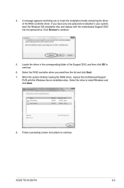
Select the drive to continue. 6. 4. Locate the driver in your system, eject the Windows OS installation disc and replace with the Windows Server installation disc. ASUS TS110-E8-PI4 6-5 Follow succeeding screen instructions to continue. 5. Click Browse to continue. Select the RAID controller driver you to insert the installation media containing the driver of ...
Select the drive to continue. 6. 4. Locate the driver in your system, eject the Windows OS installation disc and replace with the Windows Server installation disc. ASUS TS110-E8-PI4 6-5 Follow succeeding screen instructions to continue. 5. Click Browse to continue. Select the RAID controller driver you to insert the installation media containing the driver of ...

User Guide
Page 120
... DVD automatically displays the main screen if Autorun is NOT enabled in your computer. Visit the ASUS website (www.asus.com) for the latest updates on Windows® Server 2008 R2 and Windows® Server 2012. 6.3 Running the Support DVD When you can install to maximize the features of your ...change at any time without notice. The main screen of the Support DVD looks exactly the same on the Windows® Server 2008 R2 and on the Windows® Server 2012 Operating System (OS). 6-6 Chapter 6: Driver installation Contact The main screen of the Support DVD contains the following tabs:...
... DVD automatically displays the main screen if Autorun is NOT enabled in your computer. Visit the ASUS website (www.asus.com) for the latest updates on Windows® Server 2008 R2 and Windows® Server 2012. 6.3 Running the Support DVD When you can install to maximize the features of your ...change at any time without notice. The main screen of the Support DVD looks exactly the same on the Windows® Server 2008 R2 and on the Windows® Server 2012 Operating System (OS). 6-6 Chapter 6: Driver installation Contact The main screen of the Support DVD contains the following tabs:...
