User Guide
Page 12
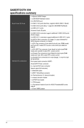
...) 24-pin EATX Power connector 8 + 4-pin EATX Power connector System panel (Q-Connector) 1 x MemOK! SABERTOOTH X99 specifications summary Back Panel I/O Ports Internal I/O connectors 1 x Optical S/PDIF Output 1 x USB BIOS Flashback button 2 x LAN (RJ45) port 2 x USB 3.1/3.0 ports (teal blue, supports ASUS USB 3.1 Boost) 4 x USB 3.0/2.0 ports (blue, 1 supports USB BIOS Flashback) 4 x USB 2.0/1.1... Black) for both 4-pin (PWM mode) and 3-pin (DC mode) CPU coolers control 5 x Assistant Fan connectors (4 x 4-pin [beige]; 1 x 4-pin for ASUS ThunderboltEX series support 1 x Clear CMOS jumper xii
...) 24-pin EATX Power connector 8 + 4-pin EATX Power connector System panel (Q-Connector) 1 x MemOK! SABERTOOTH X99 specifications summary Back Panel I/O Ports Internal I/O connectors 1 x Optical S/PDIF Output 1 x USB BIOS Flashback button 2 x LAN (RJ45) port 2 x USB 3.1/3.0 ports (teal blue, supports ASUS USB 3.1 Boost) 4 x USB 3.0/2.0 ports (blue, 1 supports USB BIOS Flashback) 4 x USB 2.0/1.1... Black) for both 4-pin (PWM mode) and 3-pin (DC mode) CPU coolers control 5 x Assistant Fan connectors (4 x 4-pin [beige]; 1 x 4-pin for ASUS ThunderboltEX series support 1 x Clear CMOS jumper xii
User Guide
Page 41
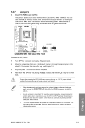
...steps above do not need to clear the RTC when the system hangs due to pins 1-2. 3. ASUS SABERTOOTH X99 1-25 Chapter 1 1.2.7 Jumpers 1. The onboard button cell battery powers the RAM data in CMOS. Move the jumper cap from pins 1-2 (default) to clear the CMOS RTC RAM data. Hold down ...and reboot the system so the BIOS can clear the CMOS memory of date, ...
...steps above do not need to clear the RTC when the system hangs due to pins 1-2. 3. ASUS SABERTOOTH X99 1-25 Chapter 1 1.2.7 Jumpers 1. The onboard button cell battery powers the RAM data in CMOS. Move the jumper cap from pins 1-2 (default) to clear the CMOS RTC RAM data. Hold down ...and reboot the system so the BIOS can clear the CMOS memory of date, ...
User Guide
Page 72
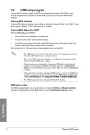
... on the system chassis. • Press the power button to turn the system off then back on how to erase the RTC RAM via the Clear CMOS button. • The BIOS setup program does not support the Bluetooth devices. See section 1.2.6 Onboard buttons and switches for information on . Entering BIOS at startup... you want to use the mouse to control the BIOS setup program. • If the system becomes unstable after changing any BIOS setting, try to clear the CMOS and reset the motherboard to the default value. Chapter 3 3-2 Chapter 3: BIOS setup
... on the system chassis. • Press the power button to turn the system off then back on how to erase the RTC RAM via the Clear CMOS button. • The BIOS setup program does not support the Bluetooth devices. See section 1.2.6 Onboard buttons and switches for information on . Entering BIOS at startup... you want to use the mouse to control the BIOS setup program. • If the system becomes unstable after changing any BIOS setting, try to clear the CMOS and reset the motherboard to the default value. Chapter 3 3-2 Chapter 3: BIOS setup
User Guide
Page 83
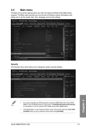
... Security menu items allow you to change the system security settings. • If you enter the Advanced Mode of the screen show [Installed]. ASUS SABERTOOTH X99 3-13 Chapter 3 3.4 Main menu The Main menu screen appears when you have forgotten your BIOS password, erase the CMOS Real Time Clock (RTC) RAM to clear the BIOS password.
... Security menu items allow you to change the system security settings. • If you enter the Advanced Mode of the screen show [Installed]. ASUS SABERTOOTH X99 3-13 Chapter 3 3.4 Main menu The Main menu screen appears when you have forgotten your BIOS password, erase the CMOS Real Time Clock (RTC) RAM to clear the BIOS password.
User Guide
Page 168
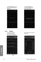
Tap CLEAR CMOS and select Yes to monitor the voltage. Monitor 4-26 Chapter 4: Software support Chapter 4 Tap the triangle icon to clear the CMOS RTC RAM data. Tap PATCH ERROR and select Yes to automatically repair your computer. 4.6.3 Monitor The Monitor page allows you to monitor voltage, temperature, and fan speed.
Tap CLEAR CMOS and select Yes to monitor the voltage. Monitor 4-26 Chapter 4: Software support Chapter 4 Tap the triangle icon to clear the CMOS RTC RAM data. Tap PATCH ERROR and select Yes to automatically repair your computer. 4.6.3 Monitor The Monitor page allows you to monitor voltage, temperature, and fan speed.


