
User Manual
Page 3
Guardian Angel 1-4 1.3.5 ASUS EZ DIY 1-4 1.3.6 Other special features 1-5 Chapter 2: Hardware information 2.1 Before you proceed 2-1 2.2 Motherboard...fan assembly installation 2-27 2.3.4 DIMM installation 2-29 2.3.5 Motherboard installation 2-30 2.3.6 ATX Power connection 2-32 2.3.7 SATA device connection 2-33 2.3.8 Front I/O Connector 2-34 2.3.9 Expension Card installation 2-35 iii Thermal Solutions 1-3 1.3.3 "TUF ENGINE!" Power Design 1-3 1.3.4 "Safe & Stable!" Contents Contents...iii Notices ...vi Safety information...vii About this guide...viii SABERTOOTH P67...
Guardian Angel 1-4 1.3.5 ASUS EZ DIY 1-4 1.3.6 Other special features 1-5 Chapter 2: Hardware information 2.1 Before you proceed 2-1 2.2 Motherboard...fan assembly installation 2-27 2.3.4 DIMM installation 2-29 2.3.5 Motherboard installation 2-30 2.3.6 ATX Power connection 2-32 2.3.7 SATA device connection 2-33 2.3.8 Front I/O Connector 2-34 2.3.9 Expension Card installation 2-35 iii Thermal Solutions 1-3 1.3.3 "TUF ENGINE!" Power Design 1-3 1.3.4 "Safe & Stable!" Contents Contents...iii Notices ...vi Safety information...vii About this guide...viii SABERTOOTH P67...
User Manual
Page 12
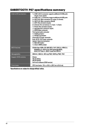
... 2.0, WfM 2.0, SM BIOS 2.5, ACPI 2.0a, Multi-language BIOS, ASUS EZ Flash 2, ASUS CrashFree BIOS 3 WfM 2.0, DMI 2.0, WOL by PME, WOR by PME, PXE Drivers ASUS Utilities ASUS Update Anti-virus software (OEM version) ATX form factor: 12 in ...CPU Fan connector (4-pin) 2 x Chassis Fan connectors (1 x 4-pin, 1 x 3-pin) 1 x Power Fan connector (3-pin) 1 x Assistant Fan connector (3-pin) 1 x IEEE1394a connector Front panel audio connector 1 x COM connector 1 x S/PDIF Out header 24-pin EATX Power connector 8-pin EATX 12V Power connector System Panel (Q-Connector) 1 x MemOK! SABERTOOTH P67 specifications ...
... 2.0, WfM 2.0, SM BIOS 2.5, ACPI 2.0a, Multi-language BIOS, ASUS EZ Flash 2, ASUS CrashFree BIOS 3 WfM 2.0, DMI 2.0, WOL by PME, WOR by PME, PXE Drivers ASUS Utilities ASUS Update Anti-virus software (OEM version) ATX form factor: 12 in ...CPU Fan connector (4-pin) 2 x Chassis Fan connectors (1 x 4-pin, 1 x 3-pin) 1 x Power Fan connector (3-pin) 1 x Assistant Fan connector (3-pin) 1 x IEEE1394a connector Front panel audio connector 1 x COM connector 1 x S/PDIF Out header 24-pin EATX Power connector 8-pin EATX 12V Power connector System Panel (Q-Connector) 1 x MemOK! SABERTOOTH P67 specifications ...

User Manual
Page 13
... the list below. 1.2 Package contents Check your motherboard package for the following items. User Manual ASUS SABERTOOTH P67 motherboard User guide Support DVD 2 x Serial ATA 6.0 Gb/s cables 2 x Serial ATA 3.0 Gb/s cables 1 x ASUS SLI™ bridge connector 1 x ASUS Q-Shield 4 x Screws for assistant fan 1 x 2-in the long line of the above items is damaged or missing, contact your...
... the list below. 1.2 Package contents Check your motherboard package for the following items. User Manual ASUS SABERTOOTH P67 motherboard User guide Support DVD 2 x Serial ATA 6.0 Gb/s cables 2 x Serial ATA 3.0 Gb/s cables 1 x ASUS SLI™ bridge connector 1 x ASUS Q-Shield 4 x Screws for assistant fan 1 x 2-in the long line of the above items is damaged or missing, contact your...

User Manual
Page 15
... standard. TUF Components (Alloy Choke, Cap. & MOSFET; The Thermal Radar automatically calculates ideal fan speeds based on the motherboard, giving user the ability to monitor each component, keeping everything cooler...ASUS DIGI+ VRM, you with robust TUF chokes, solid capacitors, and MOSFETs - Digital 8+2 power phase design also expands the modulation spectrum for a complete motherboard cool down . certified by dynamically detecting system load, empowering you can easily adjust power phase performance, enabling new PWM voltage and frequency modulation controls. ASUS SABERTOOTH P67...
... standard. TUF Components (Alloy Choke, Cap. & MOSFET; The Thermal Radar automatically calculates ideal fan speeds based on the motherboard, giving user the ability to monitor each component, keeping everything cooler...ASUS DIGI+ VRM, you with robust TUF chokes, solid capacitors, and MOSFETs - Digital 8+2 power phase design also expands the modulation spectrum for a complete motherboard cool down . certified by dynamically detecting system load, empowering you can easily adjust power phase performance, enabling new PWM voltage and frequency modulation controls. ASUS SABERTOOTH P67...

User Manual
Page 16
...AI Suite II With its user-friendly interface, ASUS AI Suite II consolidates all -in-one software offers diverse and ease to supervise energy management, fan speed control, voltage and sensor readings. ASUS Q-Connector ASUS Q-Connector allows you to use software package. Refer... Chapter 3 for experienced performance enthusiasts that goes beyond traditional keyboard BIOS input to switch back and forth between different utilities. ASUS Q-Design ASUS Q-Design enhances your system boot success. Chapter 1 1.3.4 "Safe & Stable!" quickly ensures memory boot compatibility. The exclusive ...
...AI Suite II With its user-friendly interface, ASUS AI Suite II consolidates all -in-one software offers diverse and ease to supervise energy management, fan speed control, voltage and sensor readings. ASUS Q-Connector ASUS Q-Connector allows you to use software package. Refer... Chapter 3 for experienced performance enthusiasts that goes beyond traditional keyboard BIOS input to switch back and forth between different utilities. ASUS Q-Design ASUS Q-Design enhances your system boot success. Chapter 1 1.3.4 "Safe & Stable!" quickly ensures memory boot compatibility. The exclusive ...

User Manual
Page 21
... audio connector (10-1 pin AAFP) Page 2-21 2-20 2-4 2-5 2-13 2-18 2-17 2-15 2-16 2-12 2-23 2-17 2-14 2-18 2-19 2-19 2-21 Chapter 2 ASUS SABERTOOTH P67 2-3 MemOK! CPU, chassis, power, and assistant fan connectors (4-pin CPU_FAN, 4-pin CHA_FAN1, 3-pin CHA_FAN2, 3-pin PWR_FAN, 3-pin ASST_FAN) 3. Clear RTC RAM (3-pin CLRTC) 11. USB 2.0 connectors (10-1 pin USB910...
... audio connector (10-1 pin AAFP) Page 2-21 2-20 2-4 2-5 2-13 2-18 2-17 2-15 2-16 2-12 2-23 2-17 2-14 2-18 2-19 2-19 2-21 Chapter 2 ASUS SABERTOOTH P67 2-3 MemOK! CPU, chassis, power, and assistant fan connectors (4-pin CPU_FAN, 4-pin CHA_FAN1, 3-pin CHA_FAN2, 3-pin PWR_FAN, 3-pin ASST_FAN) 3. Clear RTC RAM (3-pin CLRTC) 11. USB 2.0 connectors (10-1 pin USB910...

User Manual
Page 29
... Audio - - - - - Refer to page 2-22 for details. shared - - - shared - - - - - - PCIe 2.0 x1_2 configuration U3 Mode X1 Mode * Refer to page 3-20 for details. • Connect a chassis fan to get better performance. • We recommend that you provide sufficient power when running CrossFireX™ or SLI™ mode. ASUS SABERTOOTH P67 2-11 shared - - - - -
... Audio - - - - - Refer to page 2-22 for details. shared - - - shared - - - - - - PCIe 2.0 x1_2 configuration U3 Mode X1 Mode * Refer to page 3-20 for details. • Connect a chassis fan to get better performance. • We recommend that you provide sufficient power when running CrossFireX™ or SLI™ mode. ASUS SABERTOOTH P67 2-11 shared - - - - -

User Manual
Page 38
..., ensuring that the black wire of each cable matches the ground pin of maximum 1A (12 W) fan power. • If you install two VGA cards, we recommend that you plug the rear chassis fan cable to the fan connectors. Insufficient air flow inside the system may damage the motherboard components. CPU, chassis, power...
..., ensuring that the black wire of each cable matches the ground pin of maximum 1A (12 W) fan power. • If you install two VGA cards, we recommend that you plug the rear chassis fan cable to the fan connectors. Insufficient air flow inside the system may damage the motherboard components. CPU, chassis, power...
User Manual
Page 42
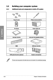
Chapter 2 2.3 Building your computer system 2.3.1 Additional tools and components to build a PC system 1 bag of screws Philips (cross) screwdriver PC chassis Power supply unit Intel LGA 1155 CPU Intel LGA 1155 compatible CPU Fan DIMM SATA hard disk drive SATA optical disc drive (optional) Graphics card (optional) The tools and components in the table above are not included in the motherboard package. 2-24 Chapter 2: Hardware information
Chapter 2 2.3 Building your computer system 2.3.1 Additional tools and components to build a PC system 1 bag of screws Philips (cross) screwdriver PC chassis Power supply unit Intel LGA 1155 CPU Intel LGA 1155 compatible CPU Fan DIMM SATA hard disk drive SATA optical disc drive (optional) Graphics card (optional) The tools and components in the table above are not included in the motherboard package. 2-24 Chapter 2: Hardware information

User Manual
Page 45
Chapter 2 2.3.3 CPU heatsink and fan assembly installation Apply the Thermal Interface Material to the CPU heatsink and CPU before you install the heatsink and fan if necessary. To install the CPU heatsink and fan assembly 1 A B 2 B A 3 4 ASUS SABERTOOTH P67 2-27
Chapter 2 2.3.3 CPU heatsink and fan assembly installation Apply the Thermal Interface Material to the CPU heatsink and CPU before you install the heatsink and fan if necessary. To install the CPU heatsink and fan assembly 1 A B 2 B A 3 4 ASUS SABERTOOTH P67 2-27

User Manual
Page 46
To uninstall the CPU heatsink and fan assembly 1 2 B A B A Chapter 2 2-28 Chapter 2: Hardware information
To uninstall the CPU heatsink and fan assembly 1 2 B A B A Chapter 2 2-28 Chapter 2: Hardware information

User Manual
Page 60
...system performance mode and boot device priority. The default screen for details. EZ Mode Monday [11/1/2010] SABERTOOTH P67 BIOS Version : 0401 CPU Type : Intel(R) Core(TM) i5-2400 CPU @ 3.10GHz Total Memory...(DDR3 1066MHz) Build Date : 10/26/2010 Speed : 3100 MHz Exit/Advanced Mode English Temperature Voltage Fan Speed CPU +113.0ºF/+45.0ºC CPU 1.248V 5V 5.160V CPU_FAN 3325RPM PWR_FAN N/A MB +75.2&#... system properties of the selected mode on the right hand side Normal mode ASUS Optimal mode Selects the boot device priority • The boot device options vary...
...system performance mode and boot device priority. The default screen for details. EZ Mode Monday [11/1/2010] SABERTOOTH P67 BIOS Version : 0401 CPU Type : Intel(R) Core(TM) i5-2400 CPU @ 3.10GHz Total Memory...(DDR3 1066MHz) Build Date : 10/26/2010 Speed : 3100 MHz Exit/Advanced Mode English Temperature Voltage Fan Speed CPU +113.0ºF/+45.0ºC CPU 1.248V 5V 5.160V CPU_FAN 3325RPM PWR_FAN N/A MB +75.2&#... system properties of the selected mode on the right hand side Normal mode ASUS Optimal mode Selects the boot device priority • The boot device options vary...

User Manual
Page 61
To access the EZ Mode, click Exit, then select ASUS EZ Mode. Copyright (C) 2010 American Megatrends, Inc. The figure below shows an example of the screen has the following sections for the detailed configurations...the advanced system settings For displaying the system temperature, power status, and changing the fan settings. 3.2.2 Advanced Mode The Advanced Mode provides advanced options for special functions For selecting the exit options and loading default settings Chapter 3 ASUS SABERTOOTH P67 3-3 Back button Menu items Menu bar Configuration fields EFI BIOS Utility - Advanced ...
To access the EZ Mode, click Exit, then select ASUS EZ Mode. Copyright (C) 2010 American Megatrends, Inc. The figure below shows an example of the screen has the following sections for the detailed configurations...the advanced system settings For displaying the system temperature, power status, and changing the fan settings. 3.2.2 Advanced Mode The Advanced Mode provides advanced options for special functions For selecting the exit options and loading default settings Chapter 3 ASUS SABERTOOTH P67 3-3 Back button Menu items Menu bar Configuration fields EFI BIOS Utility - Advanced ...

User Manual
Page 81
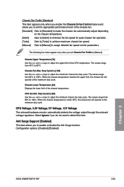
...;o�t�c�o��n�n�e��c�te��d��to display the detected temperatures. Chapter 3 ASUS SABERTOOTH P67 3-23 Select Ignore if you to change the fan settings. CPU Temperature / MB Temperature �[x�x�x��º�C�/x�x�x��º�F�] The...
...;o�t�c�o��n�n�e��c�te��d��to display the detected temperatures. Chapter 3 ASUS SABERTOOTH P67 3-23 Select Ignore if you to change the fan settings. CPU Temperature / MB Temperature �[x�x�x��º�C�/x�x�x��º�F�] The...
User Manual
Page 82
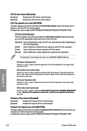
...;u�e�s��ra�n��g�e��fr�o�m��0��%� to disable or set the chassis fan warning speed. Duty Cycle(%) [100] Use the and keys to 75ºC. Configuration options: [Ignore] [200 RPM] [300 RPM] [400 ... from 20ºC to [Manual]. The values range from 20ºC to adjust the maximum CPU fan duty cycle. CPU Fan Min. The following four items appear only when you to set CPU Fan Profile to 75ºC. Configuration options: [Ignore] [200 RPM] [300 RPM] [400 RPM] ...
...;u�e�s��ra�n��g�e��fr�o�m��0��%� to disable or set the chassis fan warning speed. Duty Cycle(%) [100] Use the and keys to 75ºC. Configuration options: [Ignore] [200 RPM] [300 RPM] [400 ... from 20ºC to [Manual]. The values range from 20ºC to adjust the maximum CPU fan duty cycle. CPU Fan Min. The following four items appear only when you to set CPU Fan Profile to 75ºC. Configuration options: [Ignore] [200 RPM] [300 RPM] [400 RPM] ...
User Manual
Page 83
.... Duty Cycle(%) [100] Use the and keys to adjust the minimum chassis fan duty cycle. CPU Fan Min. Duty Cycle(%) [60] Use the and keys to adjust the maximum chassis fan duty cycle. Configuration options: [Disabled] [Enabled] Chapter 3 ASUS SABERTOOTH P67 3-25 Anti Surge Support [Enabled] This item allows you do not want to detect this...
.... Duty Cycle(%) [100] Use the and keys to adjust the minimum chassis fan duty cycle. CPU Fan Min. Duty Cycle(%) [60] Use the and keys to adjust the maximum chassis fan duty cycle. Configuration options: [Disabled] [Enabled] Chapter 3 ASUS SABERTOOTH P67 3-25 Anti Surge Support [Enabled] This item allows you do not want to detect this...
User Manual
Page 111
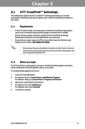
...65533;o�r�d��e�ta��il�s�. • We recommend that you install additional chassis fans for better thermal environment. • Visit the ATI Game website (http://game.amd.com) for the latest certified ...XP, select Add/Remove. To uninstall existing graphics card drivers: 1. Turn off your current graphics card driver/s. 4. Select your computer. ASUS SABERTOOTH P67 5-1 Follow the installation procedures in this section. 5.1.1 Requirements • In Dual CrossFireX mode, you should have two identical CrossFireX-ready ...
...65533;o�r�d��e�ta��il�s�. • We recommend that you install additional chassis fans for better thermal environment. • Visit the ATI Game website (http://game.amd.com) for the latest certified ...XP, select Add/Remove. To uninstall existing graphics card drivers: 1. Turn off your current graphics card driver/s. 4. Select your computer. ASUS SABERTOOTH P67 5-1 Follow the installation procedures in this section. 5.1.1 Requirements • In Dual CrossFireX mode, you should have two identical CrossFireX-ready ...
User Manual
Page 114
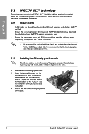
... technology. Chapter 5 5.2 NVIDIA® SLI™ technology The motherboard supports the NVIDIA® SLI™ (Scalable Link Interface) technology that allows you install additional chassis fans for better thermal environment. • Visit the NVIDIA zone website (http://www.nzone.com) for the latest certified graphics card and supported 3D application list...
... technology. Chapter 5 5.2 NVIDIA® SLI™ technology The motherboard supports the NVIDIA® SLI™ (Scalable Link Interface) technology that allows you install additional chassis fans for better thermal environment. • Visit the NVIDIA zone website (http://www.nzone.com) for the latest certified graphics card and supported 3D application list...

User Manual
Page 3
... Solutions 1-3 1.3.3 "TUF ENGINE!" Power Design 1-3 1.3.4 "Safe & Stable!" Guardian Angel 1-4 1.3.5 ASUS EZ DIY 1-4 1.3.6 Other special features 1-5 Chapter 2: Hardware information 2.1 Before you proceed 2-1 2.2 Motherboard...fan assembly installation 2-27 2.3.4 DIMM installation 2-29 2.3.5 Motherboard installation 2-30 2.3.6 ATX Power connection 2-32 2.3.7 SATA device connection 2-33 2.3.8 Front I/O Connector 2-34 2.3.9 Expension Card installation 2-35 iii Contents Contents...iii Notices ...vi Safety information...vii About this guide...viii SABERTOOTH P67...
... Solutions 1-3 1.3.3 "TUF ENGINE!" Power Design 1-3 1.3.4 "Safe & Stable!" Guardian Angel 1-4 1.3.5 ASUS EZ DIY 1-4 1.3.6 Other special features 1-5 Chapter 2: Hardware information 2.1 Before you proceed 2-1 2.2 Motherboard...fan assembly installation 2-27 2.3.4 DIMM installation 2-29 2.3.5 Motherboard installation 2-30 2.3.6 ATX Power connection 2-32 2.3.7 SATA device connection 2-33 2.3.8 Front I/O Connector 2-34 2.3.9 Expension Card installation 2-35 iii Contents Contents...iii Notices ...vi Safety information...vii About this guide...viii SABERTOOTH P67...

User Manual
Page 12
... BIOS 3 WfM 2.0, DMI 2.0, WOL by PME, WOR by PME, PXE Drivers ASUS Utilities ASUS Update Anti-virus software (OEM version) ATX form factor: 12 in . (30.5 cm x 24.4 cm) *Specifications are subject to change without notice. x 9.6 in . SABERTOOTH P67 specifications summary Internal I/O connectors BIOS features Manageability Support DVD contents Form factor 1 x USB 3.0/2.0 connector supports...
... BIOS 3 WfM 2.0, DMI 2.0, WOL by PME, WOR by PME, PXE Drivers ASUS Utilities ASUS Update Anti-virus software (OEM version) ATX form factor: 12 in . (30.5 cm x 24.4 cm) *Specifications are subject to change without notice. x 9.6 in . SABERTOOTH P67 specifications summary Internal I/O connectors BIOS features Manageability Support DVD contents Form factor 1 x USB 3.0/2.0 connector supports...


