
User Guide
Page 2
...this manual ae furnished for informational use or data, interruption of business and the like), even if ASUS has been advised of the possibility of ASUSTeK COMPUTER INC. ("ASUS"). Specifications and information contained in any form or by any kind, either express or implied, including but ...Reserved. Products and corporate names appearing in it , may not be registered trademarks or copyrights of any means, except documentation kept by ASUS; ii Product warranty or service will not be liable for any indirect, special, incidental, or consequential damages (including damages for any ...
...this manual ae furnished for informational use or data, interruption of business and the like), even if ASUS has been advised of the possibility of ASUSTeK COMPUTER INC. ("ASUS"). Specifications and information contained in any form or by any kind, either express or implied, including but ...Reserved. Products and corporate names appearing in it , may not be registered trademarks or copyrights of any means, except documentation kept by ASUS; ii Product warranty or service will not be liable for any indirect, special, incidental, or consequential damages (including damages for any ...
User Guide
Page 3
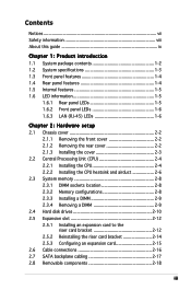
Contents Notices vii Safety information viii About this guide ix Chapter 1: Product introduction 1.1 System package contents 1-2 1.2 System specifications 1-3 1.3 Front panel features 1-4 1.4 Rear panel features 1-4 1.5 Internal features 1-5 1.6 LED information 1-5 1.6.1 Rear panel LEDs 1-5 1.6.2 Front panel LEDs 1-6 1.6.3 LAN (RJ-45) LEDs 1-6 Chapter 2: Hardware setup 2.1 Chassis cover 2-2 2.1.1 ...
Contents Notices vii Safety information viii About this guide ix Chapter 1: Product introduction 1.1 System package contents 1-2 1.2 System specifications 1-3 1.3 Front panel features 1-4 1.4 Rear panel features 1-4 1.5 Internal features 1-5 1.6 LED information 1-5 1.6.1 Rear panel LEDs 1-5 1.6.2 Front panel LEDs 1-6 1.6.3 LAN (RJ-45) LEDs 1-6 Chapter 2: Hardware setup 2.1 Chassis cover 2-2 2.1.1 ...
User Guide
Page 6
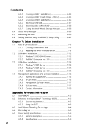
...38 6.3.7 Exiting the Intel® Matrix Storage Manager 6-38 6.4 Global Array Manager 6-39 6.5 Rebuilding the RAID 6-39 6.6 Setting the Boot array use MB BIOS Setup Utility 6-42 Chapter 7: Driver installation 7.1 RAID driver installation 7-2 7.1.1 Creating a RAID driver disk 7-2 7.1.2 Installing the RAID controller driver 7-3 7.2...SpeedStep® Technology (EIST A-2 A.2.1 System requirements A-2 A.2.2 Using the EIST A-3 A.3 Intel® Hyper-Threading Technology A-4 A.4 Block diagram A-5 A.5 Power supply specifications A-6 A.1.1 General description A-6 A.1.2 Specifications A-6 vi
...38 6.3.7 Exiting the Intel® Matrix Storage Manager 6-38 6.4 Global Array Manager 6-39 6.5 Rebuilding the RAID 6-39 6.6 Setting the Boot array use MB BIOS Setup Utility 6-42 Chapter 7: Driver installation 7.1 RAID driver installation 7-2 7.1.1 Creating a RAID driver disk 7-2 7.1.2 Installing the RAID controller driver 7-3 7.2...SpeedStep® Technology (EIST A-2 A.2.1 System requirements A-2 A.2.2 Using the EIST A-3 A.3 Intel® Hyper-Threading Technology A-4 A.4 Block diagram A-5 A.5 Power supply specifications A-6 A.1.1 General description A-6 A.1.2 Specifications A-6 vi

User Guide
Page 9
... the motherboard that comes with at least basic knowledge of configuring a server. Detailed descriptions of the server, including sections on front panel and rear panel specifications. 2. This chapter includes the motherboard layout, jumper settings, and connector locations. 5. Chapter 6: RAID configuration This chapter tells how to install optional components into the barebone...
... the motherboard that comes with at least basic knowledge of configuring a server. Detailed descriptions of the server, including sections on front panel and rear panel specifications. 2. This chapter includes the motherboard layout, jumper settings, and connector locations. 5. Chapter 6: RAID configuration This chapter tells how to install optional components into the barebone...
User Guide
Page 11
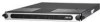
Product introduction Chapter 1 This chapter describes the general features of the chassis kit. ASUS RS120-E3/PA4 1-1 It includes sections on front panel and rear panel specifications.
Product introduction Chapter 1 This chapter describes the general features of the chassis kit. ASUS RS120-E3/PA4 1-1 It includes sections on front panel and rear panel specifications.

User Guide
Page 13
... RAGE-XL PCI-based VGA controller with 8 MB display memory Expansion slots 1 x PCI Express x8 slot (PCI Express 1.0a) 1 x PCI-X 133 MHz/64-bit slot (PCI-X 1.0) 1 x PCI 33 MHz/32-bit/5V slot (PCI 2.3)* 1 x mini-PCI socket for debug card. ASUS RS120-E3/PA4 1-3 RAID 0, RAID 1, or RAID ... mm (l) x 445 mm (w) x 43.6 mm (h) *The PCI 33/32 bit slot only use for ASUS® Server Management Board Storage 1 x Ultra ATA 100/66/33 device (slim type optical drive) 4 x SATAII-300 hard disk drive with - 1.2 System specifications The ASUS RS120-E3/PA4 is a 1U barebone server system featuring the...
... RAGE-XL PCI-based VGA controller with 8 MB display memory Expansion slots 1 x PCI Express x8 slot (PCI Express 1.0a) 1 x PCI-X 133 MHz/64-bit slot (PCI-X 1.0) 1 x PCI 33 MHz/32-bit/5V slot (PCI 2.3)* 1 x mini-PCI socket for debug card. ASUS RS120-E3/PA4 1-3 RAID 0, RAID 1, or RAID ... mm (l) x 445 mm (w) x 43.6 mm (h) *The PCI 33/32 bit slot only use for ASUS® Server Management Board Storage 1 x Ultra ATA 100/66/33 device (slim type optical drive) 4 x SATAII-300 hard disk drive with - 1.2 System specifications The ASUS RS120-E3/PA4 is a 1U barebone server system featuring the...

User Guide
Page 61
Find the proper orientation and push down firmly until the connectors completely fit. • Use of an SSI 12 V Specification 2.0-compliant power supply unit (PSU) that provides a minimum power of a PSU with a higher power output is recommended for SSI power supply plugs... +3 Volts +3 Volts Ground +5 Volts +5 Volts +5 Volts -5 Volts Ground Ground Ground PSON# Ground -12 Volts +3 Volts 1 GND +12V DC ATX12V1 GND +12V DC ASUS RS120-E3/PA4 4-13 The system may become unstable or may not boot up . • Use of 400 W is recommended when configuring a system with a higher power rating...
Find the proper orientation and push down firmly until the connectors completely fit. • Use of an SSI 12 V Specification 2.0-compliant power supply unit (PSU) that provides a minimum power of a PSU with a higher power output is recommended for SSI power supply plugs... +3 Volts +3 Volts Ground +5 Volts +5 Volts +5 Volts -5 Volts Ground Ground Ground PSON# Ground -12 Volts +3 Volts 1 GND +12V DC ATX12V1 GND +12V DC ASUS RS120-E3/PA4 4-13 The system may become unstable or may not boot up . • Use of 400 W is recommended when configuring a system with a higher power rating...
User Guide
Page 79
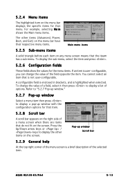
... item on the menu bar displays the specific items for that menu. Select Screen Select Item +- Change Option F1 General Help F10 Save and Exit ESC Exit Pop-up window with the configuration options for the menu items. If an item is not user-configurable. ASUS RS120-E3/PA4 5-13 You cannot select an...
... item on the menu bar displays the specific items for that menu. Select Screen Select Item +- Change Option F1 General Help F10 Save and Exit ESC Exit Pop-up window with the configuration options for the menu items. If an item is not user-configurable. ASUS RS120-E3/PA4 5-13 You cannot select an...
User Guide
Page 83
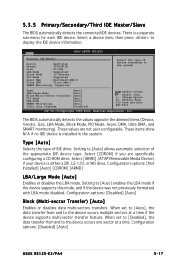
...Help F10 Save and Exit ESC Exit v02.58 (C)Copyright 1985-2004, American Megatrends, Inc. Configuration options: [Disabled] [Auto] ASUS RS120-E3/PA4 5-17 5.3.5 Primary/Secondary/Third IDE Master/Slave The BIOS automatically detects the connected IDE devices. Setting to [Auto] allows ... DMA : MultiWord DMA-2 Ultra DMA : Ultra DMA-5 SMART Monitoring: Supported Select the type of the appropriate IDE device type. These values are specifically configuring a CD-ROM drive. Configuration options: [Not Installed] [Auto] [CDROM] [ARMD] LBA/Large Mode [Auto] Enables or disables the LBA...
...Help F10 Save and Exit ESC Exit v02.58 (C)Copyright 1985-2004, American Megatrends, Inc. Configuration options: [Disabled] [Auto] ASUS RS120-E3/PA4 5-17 5.3.5 Primary/Secondary/Third IDE Master/Slave The BIOS automatically detects the connected IDE devices. Setting to [Auto] allows ... DMA : MultiWord DMA-2 Ultra DMA : Ultra DMA-5 SMART Monitoring: Supported Select the type of the appropriate IDE device type. These values are specifically configuring a CD-ROM drive. Configuration options: [Not Installed] [Auto] [CDROM] [ARMD] LBA/Large Mode [Auto] Enables or disables the LBA...
User Guide
Page 84
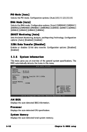
... Transfer [Disabled] Enables or disables 32-bit data transfer. Configuration options: [Disabled] [Enabled] 5.3.6 System Information This menu gives you an overview of the general system specifications. PIO Mode [Auto] Selects the PIO mode. Main AMIBIOS Version : 08.00.11 Build Date : 12/22/05 BIOS SETUP UTILITY Processor Type Speed Count.... The BIOS automatically detects the items in this menu. Configuration options: [Auto] [0] [1] [2] [3] [4] DMA Mode [Auto] Selects the DMA mode. Processor Displays the auto-detected CPU specification.
... Transfer [Disabled] Enables or disables 32-bit data transfer. Configuration options: [Disabled] [Enabled] 5.3.6 System Information This menu gives you an overview of the general system specifications. PIO Mode [Auto] Selects the PIO mode. Main AMIBIOS Version : 08.00.11 Build Date : 12/22/05 BIOS SETUP UTILITY Processor Type Speed Count.... The BIOS automatically detects the items in this menu. Configuration options: [Auto] [0] [1] [2] [3] [4] DMA Mode [Auto] Selects the DMA mode. Processor Displays the auto-detected CPU specification.
User Guide
Page 91
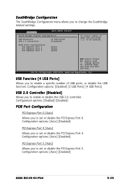
...Port 0 PCI Express Port 4 PCI Express Port 5 [Auto] [Auto] [Auto] To select number of UHCI USB Ports(USB 1.1) to enable a specific number of USB ports, or disable the USB function. Configuration options: [Disabled] [2 USB Ports] [4 USB Ports] USB 2.0 Controller [Disabled] Allows ...: [Auto] [Disabled] PCI Express Port 5 [Auto] Allows you to enable or disable the USB 2.0 controller. Configuration options: [Auto] [Disabled] ASUS RS120-E3/PA4 5-25 Change Option F1 General Help F10 Save and Exit ESC Exit v02.58 (C)Copyright 1985-2004, American Megatrends, Inc. Configuration options: [Auto...
...Port 0 PCI Express Port 4 PCI Express Port 5 [Auto] [Auto] [Auto] To select number of UHCI USB Ports(USB 1.1) to enable a specific number of USB ports, or disable the USB function. Configuration options: [Disabled] [2 USB Ports] [4 USB Ports] USB 2.0 Controller [Disabled] Allows ...: [Auto] [Disabled] PCI Express Port 5 [Auto] Allows you to enable or disable the USB 2.0 controller. Configuration options: [Auto] [Disabled] ASUS RS120-E3/PA4 5-25 Change Option F1 General Help F10 Save and Exit ESC Exit v02.58 (C)Copyright 1985-2004, American Megatrends, Inc. Configuration options: [Auto...
User Guide
Page 95
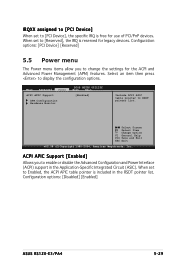
... PCI/PnP devices. When set to Enabled, the ACPI APIC table pointer is included in the Application-Specific Integrated Circuit (ASIC). Configuration options: [Disabled] [Enabled] ASUS RS120-E3/PA4 5-29 Main Advanced Power ACPI APIC Support APM Configuration Hardware Monitor BIOS SETUP UTILITY Boot Exit [... settings for the ACPI and Advanced Power Management (APM) features. IRQXX assigned to [PCI Device] When set to [PCI Device], the specific IRQ is reserved for legacy devices. Select an item then press to RSDT pointer list. Configuration options: [PCI Device] [Reserved] 5.5...
... PCI/PnP devices. When set to Enabled, the ACPI APIC table pointer is included in the Application-Specific Integrated Circuit (ASIC). Configuration options: [Disabled] [Enabled] ASUS RS120-E3/PA4 5-29 Main Advanced Power ACPI APIC Support APM Configuration Hardware Monitor BIOS SETUP UTILITY Boot Exit [... settings for the ACPI and Advanced Power Management (APM) features. IRQXX assigned to [PCI Device] When set to [PCI Device], the specific IRQ is reserved for legacy devices. Select an item then press to RSDT pointer list. Configuration options: [PCI Device] [Reserved] 5.5...
User Guide
Page 98
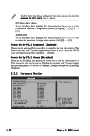
...;F] CPU1 Temperature. Fan1 Speed Fan2 Speed Fan3 Speed Fan4 Speed Fan5 Speed Fan6 Speed Fan7 Speed Fan8 Speed Fan9 Speed Smart Fan Control CPU1 Temperature MB Temperature VCORE1 Voltage [8411RPM] [8169RPM] [7594RPM] [7133RPM] [7573RPM] [7336RPM] [7317RPM] [7520RPM] [8598RPM] [Smart Fan II] [061] [050] [ 1.332V]...keyboard to make the selection. Configuration options: [00] [1]... ~ [23] Power On By PS/2 Keyboard [Disabled] Allows you to use specific keys on the system. This feature requires an ATX power supply that provides at least 1A on the +5VSB lead. Change Option F1 ...
...;F] CPU1 Temperature. Fan1 Speed Fan2 Speed Fan3 Speed Fan4 Speed Fan5 Speed Fan6 Speed Fan7 Speed Fan8 Speed Fan9 Speed Smart Fan Control CPU1 Temperature MB Temperature VCORE1 Voltage [8411RPM] [8169RPM] [7594RPM] [7133RPM] [7573RPM] [7336RPM] [7317RPM] [7520RPM] [8598RPM] [Smart Fan II] [061] [050] [ 1.332V]...keyboard to make the selection. Configuration options: [00] [1]... ~ [23] Power On By PS/2 Keyboard [Disabled] Allows you to use specific keys on the system. This feature requires an ATX power supply that provides at least 1A on the +5VSB lead. Change Option F1 ...

User Guide
Page 146
... Hard disk within the operating system. 5. If one member of the Intel Matrix Storage Console. 7. Remove the failed SATA hard disk and install the same specification of array will be the same or bigger as . 2. 4. After selecting, the volumes with new installed disk: 1. The following displays as the original hard disk...
... Hard disk within the operating system. 5. If one member of the Intel Matrix Storage Console. 7. Remove the failed SATA hard disk and install the same specification of array will be the same or bigger as . 2. 4. After selecting, the volumes with new installed disk: 1. The following displays as the original hard disk...

User Guide
Page 172
...to P4. The power supply has four plugs labeled P1 to the 8-pin SATA backplane power connector P 4 Peripheral device (optical drive) A.1.2 Specifications Output voltage regulation Output Voltage Min (V) Nom (V) +3.3V +5V +12V1 +12V2 -12V +5VSB 3.20 4.80 11.52 11.52 -...12V2 -12V -5VSB Min (V) 3.9 5.7 13.3 13.3 -13.3 5.7 Max (V) 4.5 6.5 14.5 14.5 -14.5 6.5 A-6 Appendix: Reference information A.5 Power supply specifications A.1.1 General description The 400 W SSI-type single power supply with universal AC input includes PFC and ATX-compliant output cables and connectors. Take note of...
...to P4. The power supply has four plugs labeled P1 to the 8-pin SATA backplane power connector P 4 Peripheral device (optical drive) A.1.2 Specifications Output voltage regulation Output Voltage Min (V) Nom (V) +3.3V +5V +12V1 +12V2 -12V +5VSB 3.20 4.80 11.52 11.52 -...12V2 -12V -5VSB Min (V) 3.9 5.7 13.3 13.3 -13.3 5.7 Max (V) 4.5 6.5 14.5 14.5 -14.5 6.5 A-6 Appendix: Reference information A.5 Power supply specifications A.1.1 General description The 400 W SSI-type single power supply with universal AC input includes PFC and ATX-compliant output cables and connectors. Take note of...