User Guide
Page 4
... kit items 3-2 3.2 Rack rails assembly 3-2 3.3 Attaching the rails to the rack 3-3 3.4 Rackmounting the server 3-4 Chapter 4: Motherboard information 4.1 Motherboard layout 4-2 4.2 Jumpers 4-4 4.3 Connectors 4-9 Chapter 5: BIOS setup 5.1 Managing and updating your BIOS 5-2 5.1.1 Creating a bootable floppy disk 5-2 5.1.2 AFUDOS utility 5-3 5.1.3 ASUS CrashFree BIOS 2 utility 5-6 5.1.4 ASUS Update utility 5-8 5.2 BIOS setup program 5-11 5.2.1 BIOS menu screen 5-12 5.2.2 Menu bar 5-12...
... kit items 3-2 3.2 Rack rails assembly 3-2 3.3 Attaching the rails to the rack 3-3 3.4 Rackmounting the server 3-4 Chapter 4: Motherboard information 4.1 Motherboard layout 4-2 4.2 Jumpers 4-4 4.3 Connectors 4-9 Chapter 5: BIOS setup 5.1 Managing and updating your BIOS 5-2 5.1.1 Creating a bootable floppy disk 5-2 5.1.2 AFUDOS utility 5-3 5.1.3 ASUS CrashFree BIOS 2 utility 5-6 5.1.4 ASUS Update utility 5-8 5.2 BIOS setup program 5-11 5.2.1 BIOS menu screen 5-12 5.2.2 Menu bar 5-12...
User Guide
Page 6
... Intel® Matrix Storage Manager 6-38 6.4 Global Array Manager 6-39 6.5 Rebuilding the RAID 6-39 6.6 Setting the Boot array use MB BIOS Setup Utility 6-42 Chapter 7: Driver installation 7.1 RAID driver installation 7-2 7.1.1 Creating a RAID driver disk 7-2 7.1.2 Installing the RAID... driver 7-3 7.2 LAN driver installation 7-12 7.2.1 Windows® 2000/2003 Server 7-12 7.2.2 Red Hat® Enterprise ver. 3.0 7-13 7.3 VGA driver installation 7-14 7.3.1 Windows® 2000 Server 7-14 7.3.2 Windows® 2003 Server 7-15 7.3.3 Red Hat® Enterprise ver. 3.0 7-15 7.4 Management ...
... Intel® Matrix Storage Manager 6-38 6.4 Global Array Manager 6-39 6.5 Rebuilding the RAID 6-39 6.6 Setting the Boot array use MB BIOS Setup Utility 6-42 Chapter 7: Driver installation 7.1 RAID driver installation 7-2 7.1.1 Creating a RAID driver disk 7-2 7.1.2 Installing the RAID... driver 7-3 7.2 LAN driver installation 7-12 7.2.1 Windows® 2000/2003 Server 7-12 7.2.2 Red Hat® Enterprise ver. 3.0 7-13 7.3 VGA driver installation 7-14 7.3.1 Windows® 2000 Server 7-14 7.3.2 Windows® 2003 Server 7-15 7.3.3 Red Hat® Enterprise ver. 3.0 7-15 7.4 Management ...

User Guide
Page 8
...CD-ROM Drive Safety Warning CLASS 1 LASER PRODUCT Heavy System C A U T I O N ! This server system is equipped with the server package. • Before using the server, make sure all the manuals included with a three-wire power cable and plug for assistance when moving or ... I O N ! Use the power cable with the same or equivalent type recommended by certified or experienced engineers. • Before operating the server, carefully read all cables are correctly connected and the power cables are connected. Operation Safety • Any mechanical operation on a stable surface. ...
...CD-ROM Drive Safety Warning CLASS 1 LASER PRODUCT Heavy System C A U T I O N ! This server system is equipped with the server package. • Before using the server, make sure all the manuals included with a three-wire power cable and plug for assistance when moving or ... I O N ! Use the power cable with the same or equivalent type recommended by certified or experienced engineers. • Before operating the server, carefully read all cables are correctly connected and the power cables are connected. Operation Safety • Any mechanical operation on a stable surface. ...

User Guide
Page 9
... 1. Chapter 2: Hardware setup This chapter lists the hardware setup procedures that comes with at least basic knowledge of configuring a server. Chapter 4: Motherboard information This chapter gives information about the motherboard that you may refer to when configuring the motherboard. ix ...settings through the BIOS Setup menus. Chapter 6: RAID configuration This chapter tells how to install optional components into the barebone server. 4. About this guide Audience This user guide is intended for different system components. 8. Appendix: Reference information This appendix...
... 1. Chapter 2: Hardware setup This chapter lists the hardware setup procedures that comes with at least basic knowledge of configuring a server. Chapter 4: Motherboard information This chapter gives information about the motherboard that you may refer to when configuring the motherboard. ix ...settings through the BIOS Setup menus. Chapter 6: RAID configuration This chapter tells how to install optional components into the barebone server. 4. About this guide Audience This user guide is intended for different system components. 8. Appendix: Reference information This appendix...
User Guide
Page 10
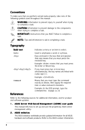
...Example: means that you must press the enclosed key. ASUS websites The ASUS websites worldwide provide updated information for product and software updates. 1. ASUS Server Web-based Management (ASWM) user guide This manual tells how to the ASUS contact information. Example: At the DOS prompt, type ... I N G : Information to prevent injury to yourself when trying to complete a task. Refer to set up and use the proprietary ASUS server management utility. 2. Example: Means that you must press two or more keys simultaneously, the key names are linked with a plus sign (+)....
...Example: means that you must press the enclosed key. ASUS websites The ASUS websites worldwide provide updated information for product and software updates. 1. ASUS Server Web-based Management (ASWM) user guide This manual tells how to the ASUS contact information. Example: At the DOS prompt, type ... I N G : Information to prevent injury to yourself when trying to complete a task. Refer to set up and use the proprietary ASUS server management utility. 2. Example: Means that you must press two or more keys simultaneously, the key names are linked with a plus sign (+)....

User Guide
Page 13
...: Broadcom® BMC5721 Gigabit Ethernet Controller VGA ATI RAGE-XL PCI-based VGA controller with - ASUS RS120-E3/PA4 1-3 1.2 System specifications The ASUS RS120-E3/PA4 is a 1U barebone server system featuring the ASUS P5MT-R motherboard. RAID 0, RAID 1, RAID 10, or software RAID 5 configuration using the LSI... (w) x 43.6 mm (h) *The PCI 33/32 bit slot only use for ASUS® Server Management Board Storage 1 x Ultra ATA 100/66/33 device (slim type optical drive) 4 x SATAII-300 hard disk drive with 8 MB display memory Expansion slots 1 x PCI Express x8 slot (PCI Express 1.0a) 1...
...: Broadcom® BMC5721 Gigabit Ethernet Controller VGA ATI RAGE-XL PCI-based VGA controller with - ASUS RS120-E3/PA4 1-3 1.2 System specifications The ASUS RS120-E3/PA4 is a 1U barebone server system featuring the ASUS P5MT-R motherboard. RAID 0, RAID 1, RAID 10, or software RAID 5 configuration using the LSI... (w) x 43.6 mm (h) *The PCI 33/32 bit slot only use for ASUS® Server Management Board Storage 1 x Ultra ATA 100/66/33 device (slim type optical drive) 4 x SATAII-300 hard disk drive with 8 MB display memory Expansion slots 1 x PCI Express x8 slot (PCI Express 1.0a) 1...

User Guide
Page 14
... the expansion slots, system power socket, and rear fans. The ports for the rear panel connectors on the front panel. 1.3 Front panel features The barebone server displays a simple yet stylish front panel with openings for the PS/2 keyboard, PS/2 mouse, USB, VGA, and Gigabit LAN do not appear on the rear...
... the expansion slots, system power socket, and rear fans. The ports for the rear panel connectors on the front panel. 1.3 Front panel features The barebone server displays a simple yet stylish front panel with openings for the PS/2 keyboard, PS/2 mouse, USB, VGA, and Gigabit LAN do not appear on the rear...
User Guide
Page 15
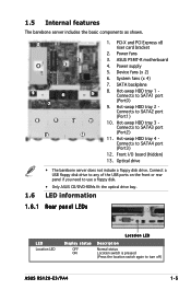
...) 12. System fans (x 4) 7. Hot-swap HDD tray 4 Connects to SATA2 port (Port1) 10. Optical drive 1.6 • The barebone server does not include a floppy disk drive. Power fans 3. Connect a USB floppy disk drive to any of the USB ports on the front or rear... switch is pressed (Press the location switch again to SATA1 port (Port0) 9. 1.5 Internal features The barebone server includes the basic components as shown. 2 1 4 3 5 6 5 7 8 9 13 10 11 12 1. Power supply 5. ASUS P5MT-R motherboard 4. Hot-swap HDD tray 1 Connects to turn off) ASUS RS120-E3/PA4 1-5
...) 12. System fans (x 4) 7. Hot-swap HDD tray 4 Connects to SATA2 port (Port1) 10. Optical drive 1.6 • The barebone server does not include a floppy disk drive. Power fans 3. Connect a USB floppy disk drive to any of the USB ports on the front or rear... switch is pressed (Press the location switch again to SATA1 port (Port0) 9. 1.5 Internal features The barebone server includes the basic components as shown. 2 1 4 3 5 6 5 7 8 9 13 10 11 12 1. Power supply 5. ASUS P5MT-R motherboard 4. Hot-swap HDD tray 1 Connects to turn off) ASUS RS120-E3/PA4 1-5
User Guide
Page 29
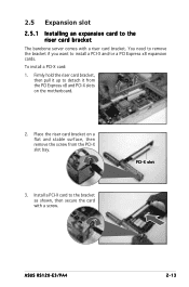
... riser card bracket on a flat and stable surface, then remove the screw from the PCI Express x8 and PCI-X slots on the motherboard. 2. PCI-X slot ASUS RS120-E3/PA4 2-13 You need to remove the bracket if you want to detach it from the PCI-X slot bay. 3. To install a PCI-X card: 1. Install ... as shown, then secure the card with a riser card bracket. 2.5 Expansion slot 2.5.1 Installing an expansion card to the riser card bracket The barebone server comes with a screw. Firmly hold the riser card bracket, then pull it up to install a PCI-X and/or a PCI Express x8 expansion cards.
... riser card bracket on a flat and stable surface, then remove the screw from the PCI Express x8 and PCI-X slots on the motherboard. 2. PCI-X slot ASUS RS120-E3/PA4 2-13 You need to remove the bracket if you want to detach it from the PCI-X slot bay. 3. To install a PCI-X card: 1. Install ... as shown, then secure the card with a riser card bracket. 2.5 Expansion slot 2.5.1 Installing an expansion card to the riser card bracket The barebone server comes with a screw. Firmly hold the riser card bracket, then pull it up to install a PCI-X and/or a PCI Express x8 expansion cards.
User Guide
Page 45
ASUS RS120-E3/PA4 2-1 Installation options Chapter 3 This chapter describes how to install the optional components and devices into the barebone server.
ASUS RS120-E3/PA4 2-1 Installation options Chapter 3 This chapter describes how to install the optional components and devices into the barebone server.
User Guide
Page 47
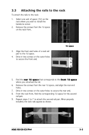
... corresponding 1U space for the second rail pair. 9. Align the front end holes of space (1U) on the rack front. 3. ASUS RS120-E3/PA4 3-3 3.3 Attaching the rails to the rack To attach the rails to install the barebone server. 2. Remove the screws from the 1U space on the rack where you attached the rail. 6.
... corresponding 1U space for the second rail pair. 9. Align the front end holes of space (1U) on the rack front. 3. ASUS RS120-E3/PA4 3-3 3.3 Attaching the rails to the rack To attach the rails to install the barebone server. 2. Remove the screws from the 1U space on the rack where you attached the rail. 6.

User Guide
Page 48
Firmly hold the server on the rack.. 2. Rack screw 3-4 Chapter 3: Installation options Tighten the two rack screws to secure the server to the back until the front panel fits the front end of the rack, and the rack screws on the server match the middle hole on both sides and insert the rear panel side to the front end of the rack rail, then carefully push the server all the way to the rack. 3.4 Rackmounting the server To mount the server to the rack: 1.
Firmly hold the server on the rack.. 2. Rack screw 3-4 Chapter 3: Installation options Tighten the two rack screws to secure the server to the back until the front panel fits the front end of the rack, and the rack screws on the server match the middle hole on both sides and insert the rear panel side to the front end of the rack rail, then carefully push the server all the way to the rack. 3.4 Rackmounting the server To mount the server to the rack: 1.

User Guide
Page 62
... 10. 9. Printer port connector (26-1 pin LPT1) This connector is for a parallel printer port. BMC connector (16-pin BMCCONN1) This connector is for the optional ASUS server management card. ® P5MT-R BMCCONN1 +5VSB +5VSB BMC SMBDATA 12CDATA1 FP_PWRBTN# BMC_PRESENT# BMC_SMI# GND +5VSB +5VSB BMC SMBCLK 12CCLK1 PSON# BMC_RST# PWROK PSONEN# P5MT-R BMC...
... 10. 9. Printer port connector (26-1 pin LPT1) This connector is for a parallel printer port. BMC connector (16-pin BMCCONN1) This connector is for the optional ASUS server management card. ® P5MT-R BMCCONN1 +5VSB +5VSB BMC SMBDATA 12CDATA1 FP_PWRBTN# BMC_PRESENT# BMC_SMI# GND +5VSB +5VSB BMC SMBCLK 12CCLK1 PSON# BMC_RST# PWROK PSONEN# P5MT-R BMC...

User Guide
Page 68
... updating your BIOS The following to create a bootable floppy disk. A S U S C r a s h F r e e B I O S 2 (Updates the BIOS using the ASUS Update or AFUDOS utilities. 5.1.1 Creating a bootable floppy disk 1. Insert a 1.44MB floppy disk into the drive. Click S t a r t from the format options field, then click S... the original motherboard BIOS file to a bootable floppy disk in DOS mode using a bootable floppy disk.) 2. Windows® XP and Server 2003 environment a. Copy the original motherboard BIOS using a bootable floppy disk or the motherboard support CD when the BIOS file fails or...
... updating your BIOS The following to create a bootable floppy disk. A S U S C r a s h F r e e B I O S 2 (Updates the BIOS using the ASUS Update or AFUDOS utilities. 5.1.1 Creating a bootable floppy disk 1. Insert a 1.44MB floppy disk into the drive. Click S t a r t from the format options field, then click S... the original motherboard BIOS file to a bootable floppy disk in DOS mode using a bootable floppy disk.) 2. Windows® XP and Server 2003 environment a. Copy the original motherboard BIOS using a bootable floppy disk or the motherboard support CD when the BIOS file fails or...
User Guide
Page 79
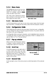
...to display the other items (Advanced, Power, Boot, and Exit) on the menu bar have their respective menu items. Main Advanced BIOS SETUP UTILITY Server Security Boot System Time System Date [12:47:28] [Tue 12/27/2005] Legacy Diskette A[Disabled] IDE Configuration System Information Exit Use [ENTER... the iteam has a sub-menu. A configurable field is enclosed in brackets, and is a brief description of the field opposite the item. ASUS RS120-E3/PA4 5-13 5.2.4 Menu items The highlighted item on the menu bar displays the specific items for the menu items. If an item is not...
...to display the other items (Advanced, Power, Boot, and Exit) on the menu bar have their respective menu items. Main Advanced BIOS SETUP UTILITY Server Security Boot System Time System Date [12:47:28] [Tue 12/27/2005] Legacy Diskette A[Disabled] IDE Configuration System Information Exit Use [ENTER... the iteam has a sub-menu. A configurable field is enclosed in brackets, and is a brief description of the field opposite the item. ASUS RS120-E3/PA4 5-13 5.2.4 Menu items The highlighted item on the menu bar displays the specific items for the menu items. If an item is not...
User Guide
Page 81
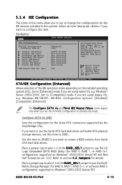
... RAID volume from Serial ATA hard disk drives. Configure SATA As [IDE] Sets the configuration for details. supported on Windows® 2000/2003 Server/XP). Windows ME/98/NT, MS-DOS. Set this menu allow you to set or change the configurations for the IDE devices installed in this...174; Enterprise ver. 3.0). WIN Me, 98, NT4.0, MS DOS)is used . Select Screen Select Item +- If you are using legacy OS, e.g. ASUS RS120-E3/PA4 5-15 Windows® Server 2000/2003. Set to [Compatible] mode if you want to use the LSI Logic Embedded SATA RAID Utility (for RAID 0, RAID 1, RAID 0+1, ...
... RAID volume from Serial ATA hard disk drives. Configure SATA As [IDE] Sets the configuration for details. supported on Windows® 2000/2003 Server/XP). Windows ME/98/NT, MS-DOS. Set this menu allow you to set or change the configurations for the IDE devices installed in this...174; Enterprise ver. 3.0). WIN Me, 98, NT4.0, MS DOS)is used . Select Screen Select Item +- If you are using legacy OS, e.g. ASUS RS120-E3/PA4 5-15 Windows® Server 2000/2003. Set to [Compatible] mode if you want to use the LSI Logic Embedded SATA RAID Utility (for RAID 0, RAID 1, RAID 0+1, ...

User Guide
Page 100
... v7.7.5] [Network: MBA v7.7.5] Specifies the boot sequence from the available devices. Select an item then press to change the system boot options. Main Advanced Server BIOS SETUP UTILITY Boot Exit Boot Settings Boot Priority Boot Settings Configuration Security Specifies the Boot Device Priority sequence. Change Option F1 General Help F10...
... v7.7.5] [Network: MBA v7.7.5] Specifies the boot sequence from the available devices. Select an item then press to change the system boot options. Main Advanced Server BIOS SETUP UTILITY Boot Exit Boot Settings Boot Priority Boot Settings Configuration Security Specifies the Boot Device Priority sequence. Change Option F1 General Help F10...
User Guide
Page 109
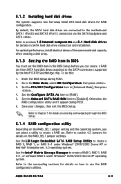
... Setup. Use the L S I L o g i c E m b e d d e d S A T A R A I n t e l® M a t r i x S t o r a g e M a n a g e r to create a RAID 0, RAID 1, or RAID 0+1 under Windows® 2000/2003 Server/XP operating system. Use the I D S e t u p U t i l i t y to create a RAID 0, RAID 1, RAID 0+1, or software RAID 5 under Windows® 2000/2003... the RAID item in BIOS You must set the RAID item in the BIOS Setup before you can create a RAID set . ASUS RS120-E3/PA4 6-3 6.1.2 Installing hard disk drives The system supports two hot-swap Serial ATA hard disk drives for details on the RAID_SEL1 ...
... Setup. Use the L S I L o g i c E m b e d d e d S A T A R A I n t e l® M a t r i x S t o r a g e M a n a g e r to create a RAID 0, RAID 1, or RAID 0+1 under Windows® 2000/2003 Server/XP operating system. Use the I D S e t u p U t i l i t y to create a RAID 0, RAID 1, RAID 0+1, or software RAID 5 under Windows® 2000/2003... the RAID item in BIOS You must set the RAID item in the BIOS Setup before you can create a RAID set . ASUS RS120-E3/PA4 6-3 6.1.2 Installing hard disk drives The system supports two hot-swap Serial ATA hard disk drives for details on the RAID_SEL1 ...
User Guide
Page 114
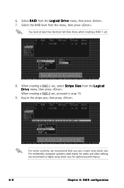
... 0 set . 8. You need at least two identical hard disk drives when creating a RAID 1 set , proceed to step 10. 9. Select R A I D from the L o g i c a l D r i v e menu, then press . 7. For server systems, we recommend a higher array block size for optimum performance. 6-8 Chapter 6: RAID configuration 6. Key-in the stripe size, then press .
... 0 set . 8. You need at least two identical hard disk drives when creating a RAID 1 set , proceed to step 10. 9. Select R A I D from the L o g i c a l D r i v e menu, then press . 7. For server systems, we recommend a higher array block size for optimum performance. 6-8 Chapter 6: RAID configuration 6. Key-in the stripe size, then press .
User Guide
Page 119
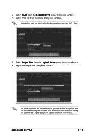
Select R A I D from the L o g i c a l D r i v e menu, then press . 9. 6. Select S t r i p e S i z e from the L o g i c a l D r i v e menu, then press . 7. For multimedia computer systems used mainly for audio and video editing, we recommend that you use a lower array block size. Select RAID 10 from the menu, then press . Key-in the stripe size, then press . You need at least four identical hard disk drives when creating a RAID 10 set. 8. For server systems, we recommend a higher array block size for optimum performance. ASUS RS120-E3/PA4 6-13
Select R A I D from the L o g i c a l D r i v e menu, then press . 9. 6. Select S t r i p e S i z e from the L o g i c a l D r i v e menu, then press . 7. For multimedia computer systems used mainly for audio and video editing, we recommend that you use a lower array block size. Select RAID 10 from the menu, then press . Key-in the stripe size, then press . You need at least four identical hard disk drives when creating a RAID 10 set. 8. For server systems, we recommend a higher array block size for optimum performance. ASUS RS120-E3/PA4 6-13