
User Guide
Page 4
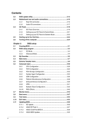
...2-23 2.5 Starting up for the first time 2-24 2.6 Turning off the computer 2-24 Chapter 3: BIOS setup 3.1 Knowing BIOS 3-1 3.2 BIOS setup program 3-2 3.2.1 EZ Mode 3-3 3.2.2 Advanced Mode 3-4 3.3 My Favorites 3-6 3.4 Main menu 3-7 3.5 Extreme Tweaker menu 3-9 3.6 Advanced menu 3-28 3.6.1 CPU Configuration 3-29 3.6.2 PCH Configuration 3-32 3.6.3 PCH ... 3-43 3.8 Boot menu 3-47 3.9 Tool menu 3-53 3.10 Exit menu 3-55 3.11 Updating BIOS 3-56 3.11.1 EZ Update 3-56 3.11.2 ASUS EZ Flash 2 3-57 3.11.3 ASUS CrashFree BIOS 3 3-58 3.11.4 ASUS BIOS Updater 3-59 iv
...2-23 2.5 Starting up for the first time 2-24 2.6 Turning off the computer 2-24 Chapter 3: BIOS setup 3.1 Knowing BIOS 3-1 3.2 BIOS setup program 3-2 3.2.1 EZ Mode 3-3 3.2.2 Advanced Mode 3-4 3.3 My Favorites 3-6 3.4 Main menu 3-7 3.5 Extreme Tweaker menu 3-9 3.6 Advanced menu 3-28 3.6.1 CPU Configuration 3-29 3.6.2 PCH Configuration 3-32 3.6.3 PCH ... 3-43 3.8 Boot menu 3-47 3.9 Tool menu 3-53 3.10 Exit menu 3-55 3.11 Updating BIOS 3-56 3.11.1 EZ Update 3-56 3.11.2 ASUS EZ Flash 2 3-57 3.11.3 ASUS CrashFree BIOS 3 3-58 3.11.4 ASUS BIOS Updater 3-59 iv
User Guide
Page 5
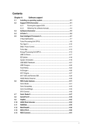
... Streamer 4.6 ROG Audio features Sonic Studio Sonic SenseAmp Sonic SoundStage DTS Connect 4.7 Sonic Radar II 4.8 GameFirst III 4.9 KeyBot 4.10 ASUS Disk Unlocker 4.11 RAMDisk 4.12 MemTweakIt 4.13 ROG CPU-Z 4.14 ROG Connect 4-1 4-1 4-1 4-3 4-4 4-4 4-7 4-7 4-8 4-10 4-11 4-13 4-14 4-17 4-18 4-19 4-21 4-22 4-23 4-26 4-27 4-29 ... 5 5-Way Optimization Turbo Processing Unit (TPU) Fan Xpert 3 DIGI+ Power Control Turbo App Energy Processing Unit (EPU) USB 3.0 Boost EZ Update System Information USB BIOS Flashback USB Charger+ Push Notice Ai Charger+ Wi-Fi Engine Wi-Fi GO!
... Streamer 4.6 ROG Audio features Sonic Studio Sonic SenseAmp Sonic SoundStage DTS Connect 4.7 Sonic Radar II 4.8 GameFirst III 4.9 KeyBot 4.10 ASUS Disk Unlocker 4.11 RAMDisk 4.12 MemTweakIt 4.13 ROG CPU-Z 4.14 ROG Connect 4-1 4-1 4-1 4-3 4-4 4-4 4-7 4-7 4-8 4-10 4-11 4-13 4-14 4-17 4-18 4-19 4-21 4-22 4-23 4-26 4-27 4-29 ... 5 5-Way Optimization Turbo Processing Unit (TPU) Fan Xpert 3 DIGI+ Power Control Turbo App Energy Processing Unit (EPU) USB 3.0 Boost EZ Update System Information USB BIOS Flashback USB Charger+ Push Notice Ai Charger+ Wi-Fi Engine Wi-Fi GO!
User Guide
Page 6
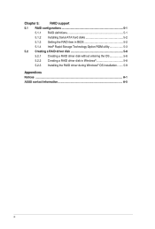
Chapter 5: RAID support 5.1 RAID configurations 5-1 5.1.1 RAID definitions 5-1 5.1.2 Installing Serial ATA hard disks 5-2 5.1.3 Setting the RAID item in BIOS 5-2 5.1.4 Intel® Rapid Storage Technology Option ROM utility 5-3 5.2 Creating a RAID driver disk 5-8 5.2.1 Creating a RAID driver disk without entering the OS 5-8 5.2.2 Creating a RAID driver disk in Windows® 5-8 5.2.3 Installing the RAID driver during Windows® OS installation 5-9 Appendices Notices A-1 ASUS contact information A-5 vi
Chapter 5: RAID support 5.1 RAID configurations 5-1 5.1.1 RAID definitions 5-1 5.1.2 Installing Serial ATA hard disks 5-2 5.1.3 Setting the RAID item in BIOS 5-2 5.1.4 Intel® Rapid Storage Technology Option ROM utility 5-3 5.2 Creating a RAID driver disk 5-8 5.2.1 Creating a RAID driver disk without entering the OS 5-8 5.2.2 Creating a RAID driver disk in Windows® 5-8 5.2.3 Installing the RAID driver during Windows® OS installation 5-9 Appendices Notices A-1 ASUS contact information A-5 vi
User Guide
Page 8
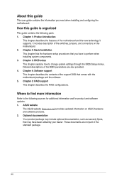
...need when installing and configuring the motherboard. Chapter 3: BIOS setup This chapter explains how to change system settings through the BIOS Setup menus. Detailed descriptions of the standard package. ASUS website The ASUS website (www.asus.com) provides updated information on the motherboard. 2. ...These documents are not part of the BIOS parameters are also provided. 4. Optional ...
...need when installing and configuring the motherboard. Chapter 3: BIOS setup This chapter explains how to change system settings through the BIOS Setup menus. Detailed descriptions of the standard package. ASUS website The ASUS website (www.asus.com) provides updated information on the motherboard. 2. ...These documents are not part of the BIOS parameters are also provided. 4. Optional ...
User Guide
Page 12
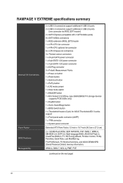
RAMPAGE V EXTREME specifications summary Internal I/O Connectors Form Factor BIOS Features Manageability 2 x USB 3.0 connectors support additional 4 USB 3.0 ports 2 x USB 2.0 connectors support additional 4 USB 2.0 ports [one connector via ROG_EXT header] 2 x SATA Express (compatible ...ATX Form Factor, 12-inch x 10.7-inch (30.5cm x 27.2 cm) 2 x 128 Mb Flash ROM, UEFI AMI BIOS, PnP, DMI2.7, WfM2.0, SM BIOS 2.8, ACPI 5.0, Multi-language BIOS, ASUS EZ Flash 2, CrashFree BIOS 3, Fl1 EZ Tuning Wizard, F6 Qfan Control, F3 My Favorites, Quick Note, Last Modified log, F12 PrintScreen, F3 Shortcut...
RAMPAGE V EXTREME specifications summary Internal I/O Connectors Form Factor BIOS Features Manageability 2 x USB 3.0 connectors support additional 4 USB 3.0 ports 2 x USB 2.0 connectors support additional 4 USB 2.0 ports [one connector via ROG_EXT header] 2 x SATA Express (compatible ...ATX Form Factor, 12-inch x 10.7-inch (30.5cm x 27.2 cm) 2 x 128 Mb Flash ROM, UEFI AMI BIOS, PnP, DMI2.7, WfM2.0, SM BIOS 2.8, ACPI 5.0, Multi-language BIOS, ASUS EZ Flash 2, CrashFree BIOS 3, Fl1 EZ Tuning Wizard, F6 Qfan Control, F3 My Favorites, Quick Note, Last Modified log, F12 PrintScreen, F3 Shortcut...
User Guide
Page 13
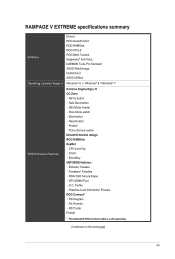
...ROG SSD Secure Erase - Safe Boot button - Extreme Tweaker - O.C. Profile - Start button - LN2 Mode header - Probelt - Graphics Card Information Preview ROG Connect* - ReTry button - GPU.DIMM Post - X.M.P. - DirectKey UEFI BIOS features : - Reset button - Tweakers' Paradise -...Diagram - CPU Level Up - RC Remote - RAMPAGE V EXTREME specifications summary o are Drivers ROG GameFirst III ROG RAMDisk ROG CPU-Z ROG Mem TweakIt Kaspersky® Anti-Virus DAEMON Tools Pro Standard ASUS WebStorage HomeCloud ASUS Utilities Operating Systems Support Windows® 8.1 / ...
...ROG SSD Secure Erase - Safe Boot button - Extreme Tweaker - O.C. Profile - Start button - LN2 Mode header - Probelt - Graphics Card Information Preview ROG Connect* - ReTry button - GPU.DIMM Post - X.M.P. - DirectKey UEFI BIOS features : - Reset button - Tweakers' Paradise -...Diagram - CPU Level Up - RC Remote - RAMPAGE V EXTREME specifications summary o are Drivers ROG GameFirst III ROG RAMDisk ROG CPU-Z ROG Mem TweakIt Kaspersky® Anti-Virus DAEMON Tools Pro Standard ASUS WebStorage HomeCloud ASUS Utilities Operating Systems Support Windows® 8.1 / ...
User Guide
Page 14
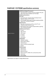
... 2 - ASUS Q-Shield - ASUS Q-Connector - USB BIOS Flashback - ASUS C.P.R.(CPU Parameter Recall) - ASUS Q-Slot - Pipe music or movies from your entertainment goes wherever you go! - xiv Media Streamer app for portable smartphonesltablets, supports iOS 7 & Android 4.0 systems Media Streamer - Push Notice - ASUS O-Design - ASUS Q-DIMM *Specifications are subject to a smart TV, your PC to change without notice. USB 3.0 Boost - RAMPAGE V EXTREME...
... 2 - ASUS Q-Shield - ASUS Q-Connector - USB BIOS Flashback - ASUS C.P.R.(CPU Parameter Recall) - ASUS Q-Slot - Pipe music or movies from your entertainment goes wherever you go! - xiv Media Streamer app for portable smartphonesltablets, supports iOS 7 & Android 4.0 systems Media Streamer - Push Notice - ASUS O-Design - ASUS Q-DIMM *Specifications are subject to a smart TV, your PC to change without notice. USB 3.0 Boost - RAMPAGE V EXTREME...
User Guide
Page 21
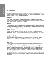
... a 40% increase in stability! With three predefined profiles for important tasks. You can also configure your motherboard at a hardware level. ASUS RAMPAGE V EXTREME 1-3 It greatly improves your junctioned data, RAMDisk features auto data backup and restore. ROG Connect links your main system to a notebook...the-fly parameter adjustments at any stage. Engineered with alloy chokes and upgraded with full control of RAMDisk back to BIOS. To protect your overclocking experience and offers advanced system control and management features purely at the same time. ROG...
... a 40% increase in stability! With three predefined profiles for important tasks. You can also configure your motherboard at a hardware level. ASUS RAMPAGE V EXTREME 1-3 It greatly improves your junctioned data, RAMDisk features auto data backup and restore. ROG Connect links your main system to a notebook...the-fly parameter adjustments at any stage. Engineered with alloy chokes and upgraded with full control of RAMDisk back to BIOS. To protect your overclocking experience and offers advanced system control and management features purely at the same time. ROG...
User Guide
Page 22
.... With the use of a multimeter device, these points can help measure your BIOS settings to others with the press of the CPU Level Up button, you can instantly apply custom profiles calibrated by the world's leading overclockers. With Extreme Tweaker, you can adjust the system settings such as an external console. It...
.... With the use of a multimeter device, these points can help measure your BIOS settings to others with the press of the CPU Level Up button, you can instantly apply custom profiles calibrated by the world's leading overclockers. With Extreme Tweaker, you can adjust the system settings such as an external console. It...

User Guide
Page 23
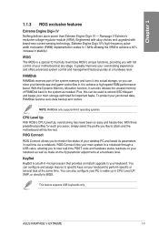
... offers a hassle-free updating solution for your ultimate convenience. 1.1.4 ASUS special features Al Suite 3 CU With its user-friendly interface, ASUS Al Suite 3 consolidates all the exclusive ASUS features into a single software package. Simply install a USB storage device containing the BIOS file, press the BIOS Flashback button for UEFI BIOS updates and download the latest BIOS automatically. ASUS RAMPAGE V EXTREME 1-5
... offers a hassle-free updating solution for your ultimate convenience. 1.1.4 ASUS special features Al Suite 3 CU With its user-friendly interface, ASUS Al Suite 3 consolidates all the exclusive ASUS features into a single software package. Simply install a USB storage device containing the BIOS file, press the BIOS Flashback button for UEFI BIOS updates and download the latest BIOS automatically. ASUS RAMPAGE V EXTREME 1-5
User Guide
Page 27
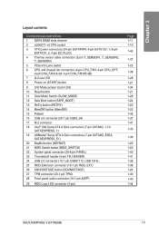
... connectors (7-pin SATA6G_1-10; SATAEXPRESS_1) 19 ASMedia® Serial ATA 6 Gb/s connectors (7-pin SATA6G_E3E4; SATAEXPRESS_E1) 20 KeyBot button (KEYBOT) 21 BIOS Switch button (BIOS_SWITCH) 22 System panel connector (20-8 pin PANEL) 23 Thunderbolt header (5-pin TB_HEADER) 24 USB 2.0 connector (10-1 pin USB91112...21 1-26 1-24 1-23 1-22 1-45 1-37 1-41 1-35 1-36 1-25 1-23 1-43 1-41 1-38 1-36 1-24 1-40 1-40 1-44 ASUS RAMPAGE V EXTREME 1-9 Layout contents Connectors/Jumpers/Slots 1 DDR4 DIMM slots channel 2 LGA2011-v3 CPU socket 3 ATX power connectors (24-pin EATXPWR; 4-pin EATX12V_1; 8-pin ...
... connectors (7-pin SATA6G_1-10; SATAEXPRESS_1) 19 ASMedia® Serial ATA 6 Gb/s connectors (7-pin SATA6G_E3E4; SATAEXPRESS_E1) 20 KeyBot button (KEYBOT) 21 BIOS Switch button (BIOS_SWITCH) 22 System panel connector (20-8 pin PANEL) 23 Thunderbolt header (5-pin TB_HEADER) 24 USB 2.0 connector (10-1 pin USB91112...21 1-26 1-24 1-23 1-22 1-45 1-37 1-41 1-35 1-36 1-25 1-23 1-43 1-41 1-38 1-36 1-24 1-40 1-40 1-44 ASUS RAMPAGE V EXTREME 1-9 Layout contents Connectors/Jumpers/Slots 1 DDR4 DIMM slots channel 2 LGA2011-v3 CPU socket 3 ATX power connectors (24-pin EATXPWR; 4-pin EATX12V_1; 8-pin ...

User Guide
Page 35
... modules inserted into four red slots and two black slots as Single-channel memory configuration. settings in the BIOS for the hyper DIMM support. • Visit the ASUS website for better compatibility. Single-sided DS - We suggest that you install the modules into slots Al ... • 1.2V 1.2V 1.2V • • 1.2V 1.2V 1.2V • • 1.2V 1.2V 1.2V • • 1.2V 1.2V cu IIO U Side(s): SS - ASUS RAMPAGE V EXTREME 1-17 or D.O.C.P. El Supports two (2) modules inserted into any two (2) of the red slots as one (1) module inserted into Al slot.
... modules inserted into four red slots and two black slots as Single-channel memory configuration. settings in the BIOS for the hyper DIMM support. • Visit the ASUS website for better compatibility. Single-sided DS - We suggest that you install the modules into slots Al ... • 1.2V 1.2V 1.2V • • 1.2V 1.2V 1.2V • • 1.2V 1.2V 1.2V • • 1.2V 1.2V cu IIO U Side(s): SS - ASUS RAMPAGE V EXTREME 1-17 or D.O.C.P. El Supports two (2) modules inserted into any two (2) of the red slots as one (1) module inserted into Al slot.
User Guide
Page 40
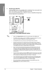
...with ones recommended in the Memory QVL (Qualified Vendors Lists) in this user manual or at www.asus.com. • If you that the BIOS has been restored to the latest BIOS version from www.asus.com after using the MemOKI function. • The MemOK! NOE MemOK! Turn off the computer ...settings. Replace the DIMMs with the motherboard may cause system boot failure. via IzQ , Eun MOW% V EXITIEWIZC Da ito ,I nami:o=olia=mrarommo anatook, RAMPAGE V EXTREME MemOK! It takes about 5-10 seconds. • If your system fails to boot up when the DIMM is the DRAM_LED lighting continuously.
...with ones recommended in the Memory QVL (Qualified Vendors Lists) in this user manual or at www.asus.com. • If you that the BIOS has been restored to the latest BIOS version from www.asus.com after using the MemOKI function. • The MemOK! NOE MemOK! Turn off the computer ...settings. Replace the DIMMs with the motherboard may cause system boot failure. via IzQ , Eun MOW% V EXITIEWIZC Da ito ,I nami:o=olia=mrarommo anatook, RAMPAGE V EXTREME MemOK! It takes about 5-10 seconds. • If your system fails to boot up when the DIMM is the DRAM_LED lighting continuously.
User Guide
Page 41
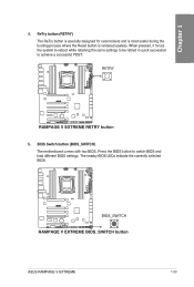
... the Reset button is rendered useless. RETRY lz.] ,,..... -I 7 I 4. Press the BIOS button to achieve a successful POST. RI .0 the system to reboot while retaining the same settings to be retried in quick succession U to switch BIOS and load different BIOS settings. b J AIM I= I I I7O L E o Ogilt Ca= ii BIOS_SWITCH 2k 0. 0 T' PI • • RAMPAGE V EXTREME BIOS_SWITCH button ASUS RAMPAGE V EXTREME 1-23
... the Reset button is rendered useless. RETRY lz.] ,,..... -I 7 I 4. Press the BIOS button to achieve a successful POST. RI .0 the system to reboot while retaining the same settings to be retried in quick succession U to switch BIOS and load different BIOS settings. b J AIM I= I I I7O L E o Ogilt Ca= ii BIOS_SWITCH 2k 0. 0 T' PI • • RAMPAGE V EXTREME BIOS_SWITCH button ASUS RAMPAGE V EXTREME 1-23

User Guide
Page 42
... to modify the settings causing boot failure. This button temporarily applies safe settings to the BIOS while retaining any overclocked settings allowing you to reboot into the BIOS safe mode. ao 7 ] ANIM v I I ff.] uu 7 CT: SOUNDSTAGE •• RAMPAGE V EXTREME SOUNDSTAGE button 1-24 Chapter 1: Product introduction SOUNDSTAGE button(SOUNDSTAGE) Press this button when overclocking...
... to modify the settings causing boot failure. This button temporarily applies safe settings to the BIOS while retaining any overclocked settings allowing you to reboot into the BIOS safe mode. ao 7 ] ANIM v I I ff.] uu 7 CT: SOUNDSTAGE •• RAMPAGE V EXTREME SOUNDSTAGE button 1-24 Chapter 1: Product introduction SOUNDSTAGE button(SOUNDSTAGE) Press this button when overclocking...
User Guide
Page 45
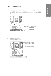
1.2.7 Onboard LEDs IL 1. U CI I IsQ EC) LLD:, BIOS_LED1 0 EEO ==70mosommol RAMPAGE V EXTREME BIOS_LED U BIOS_LED2 2. PCIEX16_1_LED1 o PCIEX16_2_LED1 o PCIEX16_3_LED1 o PCIEX16_4_LED1 ion „ O, un. o-lamilottt====rom,oot RAMPAGE V EXTREME PCIex16 LED ASUS RAMPAGE V EXTREME 1-27 Press the BIOS button to switch between BIOS1 and BIOS2 and the LED lights up when the corresponding BIOS is in IQ .0 use. PCIE Lane LED indicator Indicates the PCIE lane used. BIOS LED The BIOS LEDs help indicate the BIOS activity.
1.2.7 Onboard LEDs IL 1. U CI I IsQ EC) LLD:, BIOS_LED1 0 EEO ==70mosommol RAMPAGE V EXTREME BIOS_LED U BIOS_LED2 2. PCIEX16_1_LED1 o PCIEX16_2_LED1 o PCIEX16_3_LED1 o PCIEX16_4_LED1 ion „ O, un. o-lamilottt====rom,oot RAMPAGE V EXTREME PCIex16 LED ASUS RAMPAGE V EXTREME 1-27 Press the BIOS button to switch between BIOS1 and BIOS2 and the LED lights up when the corresponding BIOS is in IQ .0 use. PCIE Lane LED indicator Indicates the PCIE lane used. BIOS LED The BIOS LEDs help indicate the BIOS activity.
User Guide
Page 53
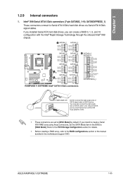
RAMPAGE V EXTREME Intel® SATA 6 Gb/s connectors SATA6G_5 SATA6G_6 OND IIGATA_TXP5 RSAGUIENS GNG FIGOTA_MG. SATAEXPRESS_1) These connectors connect to avoid mechanical conflict with the Inter Rapid Storage ... the manual bundled in the BIOS to [AHCI Mode] by default. If you can create a RAID 0, 1, 5, and 10 configuration with huge graphics cards. • These connectors are set the SATA Mode item in the motherboard support DVD. Intel® X99 Serial ATA 6 Gb/s connectors (7-pin SATA6G_1-10; ASUS RAMPAGE V EXTREME 1-35 If you installed...
RAMPAGE V EXTREME Intel® SATA 6 Gb/s connectors SATA6G_5 SATA6G_6 OND IIGATA_TXP5 RSAGUIENS GNG FIGOTA_MG. SATAEXPRESS_1) These connectors connect to avoid mechanical conflict with the Inter Rapid Storage ... the manual bundled in the BIOS to [AHCI Mode] by default. If you can create a RAID 0, 1, 5, and 10 configuration with huge graphics cards. • These connectors are set the SATA Mode item in the motherboard support DVD. Intel® X99 Serial ATA 6 Gb/s connectors (7-pin SATA6G_1-10; ASUS RAMPAGE V EXTREME 1-35 If you installed...
User Guide
Page 55
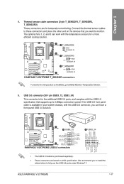
... sensor cables to to these connectors and place the other end on xHCI specification. GND SENSOR IN MEW RAMPAGE V EXTREME T_SENSOR connectors To monitor the temperature at the BIOS, go to 4.8Gbps connection speed. IntA_P2_0+ -• . - ASUS RAMPAGE V EXTREME 1-37 The optional fans 1, 2, and 3 can have a front panel USB 3.0 solution. If the USB 3.0 front panel cable...
... sensor cables to to these connectors and place the other end on xHCI specification. GND SENSOR IN MEW RAMPAGE V EXTREME T_SENSOR connectors To monitor the temperature at the BIOS, go to 4.8Gbps connection speed. IntA_P2_0+ -• . - ASUS RAMPAGE V EXTREME 1-37 The optional fans 1, 2, and 3 can have a front panel USB 3.0 solution. If the USB 3.0 front panel cable...
User Guide
Page 58
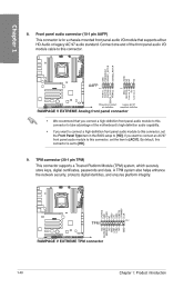
... Panel Type item in the BIOS setup to [HD]. 9. A TPM system also helps enhance the network security, protects digital identities, and ensures platform integrity. • • 7 - By default, this connector. CI AIM AAFP PIN 9 $22 2 222.2 z HD-audio-compliant Legacy AC'97 pin definition compliant definition RAMPAGE V EXTREME Analog front panel connector •...
... Panel Type item in the BIOS setup to [HD]. 9. A TPM system also helps enhance the network security, protects digital identities, and ensures platform integrity. • • 7 - By default, this connector. CI AIM AAFP PIN 9 $22 2 222.2 z HD-audio-compliant Legacy AC'97 pin definition compliant definition RAMPAGE V EXTREME Analog front panel connector •...

User Guide
Page 61
...;L4.,0g0gcai 71 Ei CC (S (S EI M ECEMIEtEIL 7D.M.C=20 HDD_LED PWRSW RESET RAMPAGE V EXTREME System panel connector • System power LED (2-pin PLED) This 2-pin connector is for the system power LED. ASUS RAMPAGE V EXTREME 1-43 The speaker allows you turn on the system power, and blinks when the ...system is in sleep or soft-off the system power. Pressing the power button turns the system on the BIOS settings. The system power LED lights ...
...;L4.,0g0gcai 71 Ei CC (S (S EI M ECEMIEtEIL 7D.M.C=20 HDD_LED PWRSW RESET RAMPAGE V EXTREME System panel connector • System power LED (2-pin PLED) This 2-pin connector is for the system power LED. ASUS RAMPAGE V EXTREME 1-43 The speaker allows you turn on the system power, and blinks when the ...system is in sleep or soft-off the system power. Pressing the power button turns the system on the BIOS settings. The system power LED lights ...


