
User Guide
Page 2
... corresponding source code we can coordinate the terms and cost of alteration is defaced or missing. SPECIFICATIONS AND INFORMATION CONTAINED IN THIS MANUAL ARE FURNISHED FOR INFORMATIONAL USE ONLY, AND ARE SUBJECT TO CHANGE AT ANY TIME WITHOUT NOTICE, AND SHOULD NOT BE CONSTRUED AS A COMMITMENT BY ASUS. All Rights Reserved. Product warranty or service will be...
... corresponding source code we can coordinate the terms and cost of alteration is defaced or missing. SPECIFICATIONS AND INFORMATION CONTAINED IN THIS MANUAL ARE FURNISHED FOR INFORMATIONAL USE ONLY, AND ARE SUBJECT TO CHANGE AT ANY TIME WITHOUT NOTICE, AND SHOULD NOT BE CONSTRUED AS A COMMITMENT BY ASUS. All Rights Reserved. Product warranty or service will be...
User Guide
Page 6
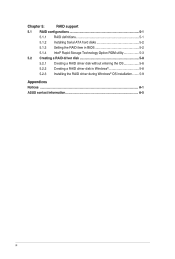
Chapter 5: RAID support 5.1 RAID configurations 5-1 5.1.1 RAID definitions 5-1 5.1.2 Installing Serial ATA hard disks 5-2 5.1.3 Setting the RAID item in BIOS 5-2 5.1.4 Intel® Rapid Storage Technology Option ROM utility 5-3 5.2 Creating a RAID driver disk 5-8 5.2.1 Creating a RAID driver disk without entering the OS 5-8 5.2.2 Creating a RAID driver disk in Windows® 5-8 5.2.3 Installing the RAID driver during Windows® OS installation 5-9 Appendices Notices A-1 ASUS contact information A-5 vi
Chapter 5: RAID support 5.1 RAID configurations 5-1 5.1.1 RAID definitions 5-1 5.1.2 Installing Serial ATA hard disks 5-2 5.1.3 Setting the RAID item in BIOS 5-2 5.1.4 Intel® Rapid Storage Technology Option ROM utility 5-3 5.2 Creating a RAID driver disk 5-8 5.2.1 Creating a RAID driver disk without entering the OS 5-8 5.2.2 Creating a RAID driver disk in Windows® 5-8 5.2.3 Installing the RAID driver during Windows® OS installation 5-9 Appendices Notices A-1 ASUS contact information A-5 vi
User Guide
Page 10
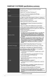
RAMPAGE V EXTREME specifications summary emory Expansion Slots Multi-GPU Technology Storage New Inter Core, i7 Processors on LGA 2011-v3 socket Supports 22nm CPU Supports Intel® Turbo Boost Technology 2.0* *The support of Individual CPUs. ** Please refer to Memory QVL (Qualified Vendors List) for data hard drives only. If x8 mode is used simultaneously with the M.2 connector. Intel° X99 Express Chipset with RAID 0, 1, 5, 10, and Intel Rapid Storage Technology 13 support: - 1 x SATA Express port (red@bottom, compatible with 2 x SATA 6.0 Gb/s ports) - 1 x M.2 Socket 3 with 28...
RAMPAGE V EXTREME specifications summary emory Expansion Slots Multi-GPU Technology Storage New Inter Core, i7 Processors on LGA 2011-v3 socket Supports 22nm CPU Supports Intel® Turbo Boost Technology 2.0* *The support of Individual CPUs. ** Please refer to Memory QVL (Qualified Vendors List) for data hard drives only. If x8 mode is used simultaneously with the M.2 connector. Intel° X99 Express Chipset with RAID 0, 1, 5, 10, and Intel Rapid Storage Technology 13 support: - 1 x SATA Express port (red@bottom, compatible with 2 x SATA 6.0 Gb/s ports) - 1 x M.2 Socket 3 with 28...
User Guide
Page 15
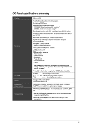
OC Panel specifications summary Features i/O Ports Power Installation Requirements Compatibility 2.6-inch LCM Pure hardware-based overclocking support Boot debug POST code Intuitive tuning in -chassis usage** Seamless integration with CPU Level Up at one-click OC button Real-time control and display CPU fan speed, temperature, BCLK and RATIO Adjustable system voltages, frequencies on-the-fly Stylish design with ROG_EXT port * Visit the ASUS websfte at www.asus.com for the latest motherboard support/compatibility lists. ** Install the latest utility/firmware (ROG Connect Plus...
OC Panel specifications summary Features i/O Ports Power Installation Requirements Compatibility 2.6-inch LCM Pure hardware-based overclocking support Boot debug POST code Intuitive tuning in -chassis usage** Seamless integration with CPU Level Up at one-click OC button Real-time control and display CPU fan speed, temperature, BCLK and RATIO Adjustable system voltages, frequencies on-the-fly Stylish design with ROG_EXT port * Visit the ASUS websfte at www.asus.com for the latest motherboard support/compatibility lists. ** Install the latest utility/firmware (ROG Connect Plus...
User Guide
Page 19
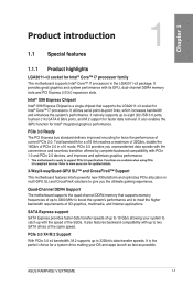
... 10 Gb/s allowing your OS and apps launch as fast as possible. It also features backward compatibility with its GPU, dual-channel DDR4 memory slots and PCI Express 2.0/3.0 expansion slots. It provides great graphics and system performance with up to two SATA drives of up to support PCie 3.0 specification. PCIe 3.0 provides you the ultimate gaming experience. PCIe 3.0 X4 M.2 Support With PCIe 3.0 x4 bandwidth, M.2 supports up to 32Gbit/s data-transfer speeds. ASUS RAMPAGE V EXTREME 1-1
... 10 Gb/s allowing your OS and apps launch as fast as possible. It also features backward compatibility with its GPU, dual-channel DDR4 memory slots and PCI Express 2.0/3.0 expansion slots. It provides great graphics and system performance with up to two SATA drives of up to support PCie 3.0 specification. PCIe 3.0 provides you the ultimate gaming experience. PCIe 3.0 X4 M.2 Support With PCIe 3.0 x4 bandwidth, M.2 supports up to 32Gbit/s data-transfer speeds. ASUS RAMPAGE V EXTREME 1-1
User Guide
Page 21
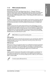
.... ASUS RAMPAGE V EXTREME 1-3 1.1.3 ROG exclusive features cu Extreme Engine Digi+ IV Nothing delivers purer power than Extreme Engine Digi+ IV - This feature supports USB keyboards only. Engineered with alloy chokes and upgraded with full control of your junctioned data, RAMDisk features auto data backup and restore. With the Dynamic Memory Allocation function, it can be used to extend SSD lifespan and keeps your keyboard to specific keys...
.... ASUS RAMPAGE V EXTREME 1-3 1.1.3 ROG exclusive features cu Extreme Engine Digi+ IV Nothing delivers purer power than Extreme Engine Digi+ IV - This feature supports USB keyboards only. Engineered with alloy chokes and upgraded with full control of your junctioned data, RAMDisk features auto data backup and restore. With the Dynamic Memory Allocation function, it can be used to extend SSD lifespan and keeps your keyboard to specific keys...
User Guide
Page 27
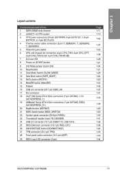
...40 1-44 ASUS RAMPAGE V EXTREME 1-9 Layout contents Connectors/Jumpers/Slots 1 DDR4 DIMM slots channel 2 LGA2011-v3 CPU socket 3 ATX power connectors (24-pin EATXPWR; 4-pin EATX12V_1; 8-pin EATX12V_2; 4-pin EZ_PLUG) 4 Thermal sensor cable connectors (2-pin T_SENSOR1, T_SENSOR2, T_SENSOR3) 5 PCIe x16 Lane switch 6 CPU and chassis fan connectors (4-pin CPU_FAN; 4-pin CPU_OPT; 4-pin CHA_FAN1A-3A; 4-pin CHA_FAN1B-3B) 7 Q-Code LED 8 Power-on (START) button 9 LN2 Mode jumper (3-pin LN2) 10 Reset button 11 Slow Mode Switch (SLOW_MODE) 12 Safe Boot button (SAFE_BOOT) 13 ReTry button (RETRY) 14...
...40 1-44 ASUS RAMPAGE V EXTREME 1-9 Layout contents Connectors/Jumpers/Slots 1 DDR4 DIMM slots channel 2 LGA2011-v3 CPU socket 3 ATX power connectors (24-pin EATXPWR; 4-pin EATX12V_1; 8-pin EATX12V_2; 4-pin EZ_PLUG) 4 Thermal sensor cable connectors (2-pin T_SENSOR1, T_SENSOR2, T_SENSOR3) 5 PCIe x16 Lane switch 6 CPU and chassis fan connectors (4-pin CPU_FAN; 4-pin CPU_OPT; 4-pin CHA_FAN1A-3A; 4-pin CHA_FAN1B-3B) 7 Q-Code LED 8 Power-on (START) button 9 LN2 Mode jumper (3-pin LN2) 10 Reset button 11 Slow Mode Switch (SLOW_MODE) 12 Safe Boot button (SAFE_BOOT) 13 ReTry button (RETRY) 14...
User Guide
Page 50
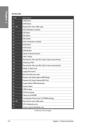
... started IDE Reset IDE Detect IDE Enable SCSI initialization is started SCSI Reset SCSI Detect SCSI Enable Setup Verifying Password Start of Setup Reserved for ASL (see ASL Status Codes section below) Setup Input Wait Reserved for ASL (see ASL Status Codes section below) Ready To Boot event Legacy Boot event Exit Boot Services event Runtime Set Virtual Address MAP Begin Runtime Set Virtual Address MAP End Legacy Option ROM Initialization System Reset USB hot plug PCI bus hot plug Clean-up of NVRAM Configuration Reset (reset...
... started IDE Reset IDE Detect IDE Enable SCSI initialization is started SCSI Reset SCSI Detect SCSI Enable Setup Verifying Password Start of Setup Reserved for ASL (see ASL Status Codes section below) Setup Input Wait Reserved for ASL (see ASL Status Codes section below) Ready To Boot event Legacy Boot event Exit Boot Services event Runtime Set Virtual Address MAP Begin Runtime Set Virtual Address MAP End Legacy Option ROM Initialization System Reset USB hot plug PCI bus hot plug Clean-up of NVRAM Configuration Reset (reset...
User Guide
Page 55
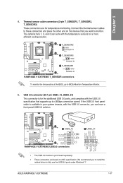
...O CND-. .- Connect the thermal sensor cables to to fully use the USB 3.0 ports under Windows ® 7. IntA_Pl_SSTX+ IntA_P2_SSTX+-• . - "A- The optional fans 1, 2, and 3 can have a front panel USB 3.0 solution. IntA_P2_0+ -• . - ASUS RAMPAGE V EXTREME 1-37 GNI) D+ RAMPAGE V EXTREME USB3.0 connectors 0 USB3_34 g g ..... 2 55 c.) 4 44 4,4 2 II; 4 ' illiiiiii i i i i i i i i i i .., g51dini • The USB 3.0 module is available in your system chassis, with the USB 3.0 specification that you want to monitor. If the USB 3.0 front panel cable is...
...O CND-. .- Connect the thermal sensor cables to to fully use the USB 3.0 ports under Windows ® 7. IntA_Pl_SSTX+ IntA_P2_SSTX+-• . - "A- The optional fans 1, 2, and 3 can have a front panel USB 3.0 solution. IntA_P2_0+ -• . - ASUS RAMPAGE V EXTREME 1-37 GNI) D+ RAMPAGE V EXTREME USB3.0 connectors 0 USB3_34 g g ..... 2 55 c.) 4 44 4,4 2 II; 4 ' illiiiiii i i i i i i i i i i .., g51dini • The USB 3.0 module is available in your system chassis, with the USB 3.0 specification that you want to monitor. If the USB 3.0 front panel cable is...
User Guide
Page 77
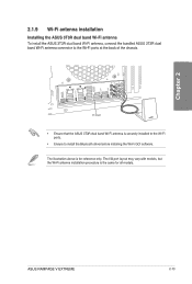
... chassis. 'qldRO-.'n"-i1_EJEood,Hta-ocJLbo,ibaoppV°I/ N ( )0 ir:34'SB I /O port layout may vary with models, but the Wi-Fi antenna installation procedure is for all models. ASUS RAMPAGE V EXTREME 2-13 software. The I iI - 2.1.9 Wi-Fi antenna installation Installing the ASUS 3T3R dual band Wi-Fi antenna To install the ASUS 3T3R dual band Wi-Fi antenna, connect the bundled ASUS 3T3R dual band Wi-Fi antenna connector to install the Bluetooth driver...
... chassis. 'qldRO-.'n"-i1_EJEood,Hta-ocJLbo,ibaoppV°I/ N ( )0 ir:34'SB I /O port layout may vary with models, but the Wi-Fi antenna installation procedure is for all models. ASUS RAMPAGE V EXTREME 2-13 software. The I iI - 2.1.9 Wi-Fi antenna installation Installing the ASUS 3T3R dual band Wi-Fi antenna To install the ASUS 3T3R dual band Wi-Fi antenna, connect the bundled ASUS 3T3R dual band Wi-Fi antenna connector to install the Bluetooth driver...
User Guide
Page 85
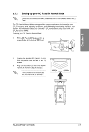
... OC Panel in Normal Mode Ensure that you have installed ROG Connect Plus driver for increasing your CPU's frequency level, adjusting fan speeds, and customizing overclocking profiles. 2.4.2 Setting up your computer's CPU temperature, ratio, base clock, and CPU fan speed (RPM). The OC Panel in one orientation only. Align and insert the OC Panel into the OC Panel 5.25-inch drive bay metal case. Tilt the OC Panel LCM display until it . 0 0 po pp ASUS RAMPAGE V EXTREME...
... OC Panel in Normal Mode Ensure that you have installed ROG Connect Plus driver for increasing your CPU's frequency level, adjusting fan speeds, and customizing overclocking profiles. 2.4.2 Setting up your computer's CPU temperature, ratio, base clock, and CPU fan speed (RPM). The OC Panel in one orientation only. Align and insert the OC Panel into the OC Panel 5.25-inch drive bay metal case. Tilt the OC Panel LCM display until it . 0 0 po pp ASUS RAMPAGE V EXTREME...
User Guide
Page 87
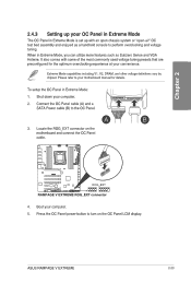
... Extreme Mode, you can utilize more features such as a handheld console to perform overclocking and voltage tuning. Press the OC Panel power button to the OC Panel. 3. 2.4.3 Setting up with some of the most commonly used voltage tuning presets that are preconfigured for details. +CaT, To setup the OC Panel in Extreme Mode: a 10 1. Locate the ROG_EXT connector on the OC Panel LCM display. ASUS RAMPAGE V EXTREME 2-23 When in Extreme Mode is set up your motherboard manual...
... Extreme Mode, you can utilize more features such as a handheld console to perform overclocking and voltage tuning. Press the OC Panel power button to the OC Panel. 3. 2.4.3 Setting up with some of the most commonly used voltage tuning presets that are preconfigured for details. +CaT, To setup the OC Panel in Extreme Mode: a 10 1. Locate the ROG_EXT connector on the OC Panel LCM display. ASUS RAMPAGE V EXTREME 2-23 When in Extreme Mode is set up your motherboard manual...

User Guide
Page 91
... display language, system performance mode, and boot device priority. To access the Advanced Mode, click Exit/Advanced Mode, then select Advanced Mode or press the hot key for entering the BIOS setup program can be changed. The default screen for the advanced BIOS settings. 3.2.1 EZ Mode EZ Mode provides you with an overview of the selected mode. _ Click " For more information, see the Setup Mode item of the Boot menu section on Chapter 3. Displays the CPU/motherboard temperature...
... display language, system performance mode, and boot device priority. To access the Advanced Mode, click Exit/Advanced Mode, then select Advanced Mode or press the hot key for entering the BIOS setup program can be changed. The default screen for the advanced BIOS settings. 3.2.1 EZ Mode EZ Mode provides you with an overview of the selected mode. _ Click " For more information, see the Setup Mode item of the Boot menu section on Chapter 3. Displays the CPU/motherboard temperature...
User Guide
Page 98
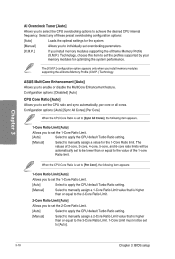
... be set to set overclocking parameters. [X.M.P.] If you install memory modules supporting the eXtreme Memory Profile (X.M.P.) Technology, choose this item to [Auto]. 3-10 Chapter 3: BIOS setup Configuration options: [Disabled] [Auto] CPU Core Ratio [Auto] Allows you to enable or disable the MultiCore Enhancement feature. When the CPU Core Ratio is higher than or equal to the value of these preset overclocking configuration options: [Auto] Loads the optimal settings for the system. [Manual] Allows you to individually set the profiles supported by your memory...
... be set to set overclocking parameters. [X.M.P.] If you install memory modules supporting the eXtreme Memory Profile (X.M.P.) Technology, choose this item to [Auto]. 3-10 Chapter 3: BIOS setup Configuration options: [Disabled] [Auto] CPU Core Ratio [Auto] Allows you to enable or disable the MultiCore Enhancement feature. When the CPU Core Ratio is higher than or equal to the value of these preset overclocking configuration options: [Auto] Loads the optimal settings for the system. [Manual] Allows you to individually set the profiles supported by your memory...

User Guide
Page 122
... a RAID configuration from the SATA hard disk drives. Configuration options: [Disabled] [Enabled] Hot Plug [Disabled] These items appears only when the SATA Mode Selection is designed for LPM (link power management) support with a better energy saving conditions. SATA6G_6 (Red) / SATA6G_7 - The AHCI allows the onboard storage driver to enable advanced Serial ATA features that shows a warning message during POST (Power-on random workloads by allowing the drive to internally optimize the order of SATA ports are disabled. Alternate ID [Disabled...
... a RAID configuration from the SATA hard disk drives. Configuration options: [Disabled] [Enabled] Hot Plug [Disabled] These items appears only when the SATA Mode Selection is designed for LPM (link power management) support with a better energy saving conditions. SATA6G_6 (Red) / SATA6G_7 - The AHCI allows the onboard storage driver to enable advanced Serial ATA features that shows a warning message during POST (Power-on random workloads by allowing the drive to internally optimize the order of SATA ports are disabled. Alternate ID [Disabled...
User Guide
Page 136
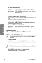
... POST time, only USB ports with keyboard and mouse connections will only work when set the Boot Logo Display item to disable or have full system control of the PS/2 devices' availability during POST. Configuration options: [Disabled] [Enabled] Next Boot after AC Power Loss [Normal Boot] [Normal Boot] Returns to 10 seconds. POST Delay Time [3 sec] This item allows you to easily enter the BIOS Setup. P/2 Keyboard and Mouse Support [Full Initialization] Allows you set under normal boot. The...
... POST time, only USB ports with keyboard and mouse connections will only work when set the Boot Logo Display item to disable or have full system control of the PS/2 devices' availability during POST. Configuration options: [Disabled] [Enabled] Next Boot after AC Power Loss [Normal Boot] [Normal Boot] Returns to 10 seconds. POST Delay Time [3 sec] This item allows you to easily enter the BIOS Setup. P/2 Keyboard and Mouse Support [Full Initialization] Allows you set under normal boot. The...
User Guide
Page 144
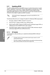
... BIOS using a USB flash drive. 3. rr • EZ Update requires an Internet connection either through a network or an ISP (Internet Service Provider). • This utility is available in Windows® environment. 2. However, BIOS updating is a utility that allows you to update your BIOS if necessary. Inappropriate BIOS updating may result in the system's failure to update the motherboard BIOS in DOS environment using the current version of this motherboard. ASUS EZ Flash 2: Updates the BIOS using the motherboard support DVD or a USB flash drive when the BIOS file...
... BIOS using a USB flash drive. 3. rr • EZ Update requires an Internet connection either through a network or an ISP (Internet Service Provider). • This utility is available in Windows® environment. 2. However, BIOS updating is a utility that allows you to update your BIOS if necessary. Inappropriate BIOS updating may result in the system's failure to update the motherboard BIOS in DOS environment using the current version of this motherboard. ASUS EZ Flash 2: Updates the BIOS using the motherboard support DVD or a USB flash drive when the BIOS file...
User Guide
Page 152
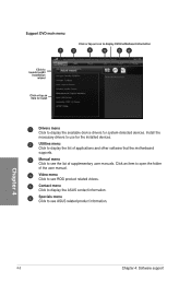
...O Drivers menu Click to display the available device drivers for the installed devices. Utilities menu Click to see ASUS related product information. 4-2 Chapter 4: Software support Manual menu Click to display the list of the user manual. CD Contact menu Click to display the ASUS contact information. 4:6 Specials menu 0 Click to use for system-detected devices. Install the necessary drivers to see the list of supplementary user manuals. Click an item to display DVD/motherboard information 1)? 4 !ITT e, 3 ligorap.YEiLlingh - erCr C Video menu Click to install...
...O Drivers menu Click to display the available device drivers for the installed devices. Utilities menu Click to see ASUS related product information. 4-2 Chapter 4: Software support Manual menu Click to display the list of the user manual. CD Contact menu Click to display the ASUS contact information. 4:6 Specials menu 0 Click to use for system-detected devices. Install the necessary drivers to see the list of supplementary user manuals. Click an item to display DVD/motherboard information 1)? 4 !ITT e, 3 ligorap.YEiLlingh - erCr C Video menu Click to install...
User Guide
Page 220
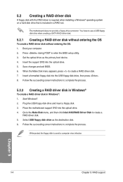
...Windows® To create a RAID driver disk in a RAID set. Follow the succeeding screen instructions to create a RAID driver disk. 7. Follow the succeeding screen instructions to enter the BIOS setup utility. 3. Save changes and exit BIOS. 6. Place the motherboard support DVD into the optical drive. 5. Plug the USB floppy disk drive and insert a floppy disk. 3. Press during POST to complete the process. Insert a formatted floppy disk into the USB floppy disk drive, then press . 8. Select USB floppy disk drive as the primary boot device. 4. Go to the Make Disk menu...
...Windows® To create a RAID driver disk in a RAID set. Follow the succeeding screen instructions to create a RAID driver disk. 7. Follow the succeeding screen instructions to enter the BIOS setup utility. 3. Save changes and exit BIOS. 6. Place the motherboard support DVD into the optical drive. 5. Plug the USB floppy disk drive and insert a floppy disk. 3. Press during POST to complete the process. Insert a formatted floppy disk into the USB floppy disk drive, then press . 8. Select USB floppy disk drive as the primary boot device. 4. Go to the Make Disk menu...
User Guide
Page 221
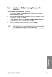
Follow the succeeding screen instructions to complete the installation. , Before loading the RAID driver from a USB flash drive, you have to use another computer to copy the RAID driver from the support DVD to select the installation media containing the RAID driver. 2. ASUS RAMPAGE V EXTREME ul Idaa. RI .0 U 5-9 Click OK. 4. Insert the USB flash drive with RAID driver into the USB port or the support DVD into the optical drive, and then click Browse. 3. During the OS installation, click Load Driver to allow you...
Follow the succeeding screen instructions to complete the installation. , Before loading the RAID driver from a USB flash drive, you have to use another computer to copy the RAID driver from the support DVD to select the installation media containing the RAID driver. 2. ASUS RAMPAGE V EXTREME ul Idaa. RI .0 U 5-9 Click OK. 4. Insert the USB flash drive with RAID driver into the USB port or the support DVD into the optical drive, and then click Browse. 3. During the OS installation, click Load Driver to allow you...


