User Guide
Page 14
Chapter summary 1.1 Welcome 1-1 1.2 Package contents 1-1 1.3 Special features 1-2 1.4 Motherboard overview 1-6 ASUS PC-DL Deluxe motherboard
Chapter summary 1.1 Welcome 1-1 1.2 Package contents 1-1 1.3 Special features 1-2 1.4 Motherboard overview 1-6 ASUS PC-DL Deluxe motherboard
User Guide
Page 15
... a powerful workstation platform solution. 1.1 Welcome! The motherboard incorporates the Intel® Xeon™ processor in your package with the list below. 1.2 Package contents Check your PC-DL Deluxe package for buying the ASUS® PC-DL Deluxe motherboard! The ASUS PC-DL Deluxe motherboard delivers a host of power computing! ASUS PC-DL Deluxe motherboard 1-1
... a powerful workstation platform solution. 1.1 Welcome! The motherboard incorporates the Intel® Xeon™ processor in your package with the list below. 1.2 Package contents Check your PC-DL Deluxe package for buying the ASUS® PC-DL Deluxe motherboard! The ASUS PC-DL Deluxe motherboard delivers a host of power computing! ASUS PC-DL Deluxe motherboard 1-1
User Guide
Page 17
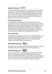
... of the peripherals plugged into the audio ports and identifies the incompatible devices, if any . ASUS POST Reporter™ The motherboard offers a new exciting feature called the ASUS POST Reporter™ to provide friendly voice messages and alerts during the Power-On Self-Tests ...LAN on the installed CPU and DRAM) to enhance system performance while still maintaining system stability. ASUS PC-DL Deluxe motherboard 1-3 Instead of boot errors, if any . ASUS Q-Fan technology The ASUS Q-Fan technology smartly adjusts the fan speeds according to the system loading to set the BIOS ...
... of the peripherals plugged into the audio ports and identifies the incompatible devices, if any . ASUS POST Reporter™ The motherboard offers a new exciting feature called the ASUS POST Reporter™ to provide friendly voice messages and alerts during the Power-On Self-Tests ...LAN on the installed CPU and DRAM) to enhance system performance while still maintaining system stability. ASUS PC-DL Deluxe motherboard 1-3 Instead of boot errors, if any . ASUS Q-Fan technology The ASUS Q-Fan technology smartly adjusts the fan speeds according to the system loading to set the BIOS ...
User Guide
Page 19
... utility allows you to update the motherboard BIOS through the Winbond ASIC. Connect to the Internet then to the ASUS FTP site nearest you to obtain the latest BIOS version for critical components. ACPI ready The Advanced Configuration power Interface...through a user-friendly interface. 1.3.2 Value-added solutions Temperature, fan, and voltage monitoring The CPU temperature is monitored for timely failure detection. ASUS PC-DL Deluxe motherboard 1-5 The system fan rotations per minute (RPM) is monitored by the ASIC (integrated in CMOS for more energy saving features for ...
... utility allows you to update the motherboard BIOS through the Winbond ASIC. Connect to the Internet then to the ASUS FTP site nearest you to obtain the latest BIOS version for critical components. ACPI ready The Advanced Configuration power Interface...through a user-friendly interface. 1.3.2 Value-added solutions Temperature, fan, and voltage monitoring The CPU temperature is monitored for timely failure detection. ASUS PC-DL Deluxe motherboard 1-5 The system fan rotations per minute (RPM) is monitored by the ASIC (integrated in CMOS for more energy saving features for ...

User Guide
Page 21
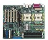
1 2 34 5 22 6 21 7 20 8 9 10 19 11 18 12 171615 1413 23 24 25 26 27 28 29 33 32 31 30 ASUS PC-DL Deluxe motherboard 1-7
1 2 34 5 22 6 21 7 20 8 9 10 19 11 18 12 171615 1413 23 24 25 26 27 28 29 33 32 31 30 ASUS PC-DL Deluxe motherboard 1-7
User Guide
Page 23
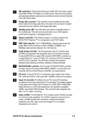
... IEEE 1394 connectors to turn off the system power before plugging or unplugging devices. 14 Speech controller. ASUS PC-DL Deluxe motherboard 1-9 This Winbond speech controller supports the ASUS POST Reporter™ for a 360K/720K/1.44M/2.88M floppy disk drive, a multi-mode parallel port,... capability. The CODEC supports surround sound output, variable sample rate conversion, analog enumeration capability, and other major audio technologies for PC health monitoring. 20 Audio CODEC. Both the primary (blue) and secondary (black) connectors are slotted to prevent incorrect insertion of...
... IEEE 1394 connectors to turn off the system power before plugging or unplugging devices. 14 Speech controller. ASUS PC-DL Deluxe motherboard 1-9 This Winbond speech controller supports the ASUS POST Reporter™ for a 360K/720K/1.44M/2.88M floppy disk drive, a multi-mode parallel port,... capability. The CODEC supports surround sound output, variable sample rate conversion, analog enumeration capability, and other major audio technologies for PC health monitoring. 20 Audio CODEC. Both the primary (blue) and secondary (black) connectors are slotted to prevent incorrect insertion of...
User Guide
Page 26
Chapter summary 2.1 Motherboard installation 2-1 2.2 Motherboard layout 2-2 2.3 Before you proceed 2-3 2.4 Central Processing Unit (CPU 2-4 2.5 System memory 2-11 2.6 Expansion slots 2-14 2.7 Jumpers 2-18 2.8 Connectors 2-21 ASUS PC-DL Deluxe motherboard
Chapter summary 2.1 Motherboard installation 2-1 2.2 Motherboard layout 2-2 2.3 Before you proceed 2-3 2.4 Central Processing Unit (CPU 2-4 2.5 System memory 2-11 2.6 Expansion slots 2-14 2.7 Jumpers 2-18 2.8 Connectors 2-21 ASUS PC-DL Deluxe motherboard
User Guide
Page 27
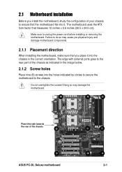
... the image below. 2.1.2 Screw holes Place nine (9) screws into the holes indicated by circles to secure the motherboard to the rear part of the chassis ASUS PC-DL Deluxe motherboard 2-1 Make sure to do so may damage the motherboard. Failure to unplug the power cord before installing or removing the motherboard. 2.1 Motherboard installation Before...
... the image below. 2.1.2 Screw holes Place nine (9) screws into the holes indicated by circles to secure the motherboard to the rear part of the chassis ASUS PC-DL Deluxe motherboard 2-1 Make sure to do so may damage the motherboard. Failure to unplug the power cord before installing or removing the motherboard. 2.1 Motherboard installation Before...
User Guide
Page 29
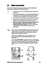
... cause severe damage to power up. This warning LED (LED1) lights up thus preventing the system to the motherboard, peripherals, and/or components. AGP_WARN1 PC-DL PC-DL Onboard LED ASUS PC-DL Deluxe motherboard ON Incorrect AGP Card OFF Correct AGP Card LED1 ON OFF CPU Type/Voltage CPU Type/Voltage not identical identical SB_PWR1 ON Standby...
... cause severe damage to power up. This warning LED (LED1) lights up thus preventing the system to the motherboard, peripherals, and/or components. AGP_WARN1 PC-DL PC-DL Onboard LED ASUS PC-DL Deluxe motherboard ON Incorrect AGP Card OFF Correct AGP Card LED1 ON OFF CPU Type/Voltage CPU Type/Voltage not identical identical SB_PWR1 ON Standby...
User Guide
Page 31
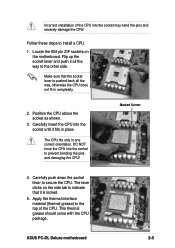
.... 3. Make sure that it fits in one correct orientation. Carefully insert the CPU into the socket may bend the pins and severely damage the CPU! ASUS PC-DL Deluxe motherboard 2-5 Carefully push down the socket lever to the top of the CPU into the socket until it is pushed back all the way, otherwise...
.... 3. Make sure that it fits in one correct orientation. Carefully insert the CPU into the socket may bend the pins and severely damage the CPU! ASUS PC-DL Deluxe motherboard 2-5 Carefully push down the socket lever to the top of the CPU into the socket until it is pushed back all the way, otherwise...
User Guide
Page 33
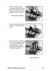
Secure the retention mechanism with cut corners) facing the memory sockets. Heatsink angled side ASUS PC-DL Deluxe motherboard 2-7 Position the heatsink on top of the CPU, having its holes with the four holes on the motherboard and the standoffs on the retention mechanism. 2. Make sure that the heatsink base fits completely on the thermal plate. Place the heatsink retention mechanism over the CPU socket, matching its angled side (with the thermal plate using four screws. 4. Heatsink retention mechanism 3.
Secure the retention mechanism with cut corners) facing the memory sockets. Heatsink angled side ASUS PC-DL Deluxe motherboard 2-7 Position the heatsink on top of the CPU, having its holes with the four holes on the motherboard and the standoffs on the retention mechanism. 2. Make sure that the heatsink base fits completely on the thermal plate. Place the heatsink retention mechanism over the CPU socket, matching its angled side (with the thermal plate using four screws. 4. Heatsink retention mechanism 3.
User Guide
Page 35
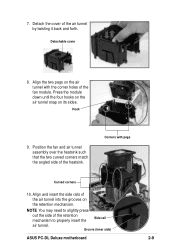
.... Align and insert the side rails of the air tunnel into the grooves on the air tunnel with pegs Curved corners 10. Groove (inner side) ASUS PC-DL Deluxe motherboard 2-9 NOTE You may need to properly insert the Side rail air tunnel. Align the two pegs on the retention mechanism. Detach the cover of...
.... Align and insert the side rails of the air tunnel into the grooves on the air tunnel with pegs Curved corners 10. Groove (inner side) ASUS PC-DL Deluxe motherboard 2-9 NOTE You may need to properly insert the Side rail air tunnel. Align the two pegs on the retention mechanism. Detach the cover of...
User Guide
Page 37
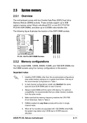
...transfer rate. When all four sockets are populated with 1GB DIMMs (total 4GB), the system may cause memory sizing error or system boot failure. ASUS PC-DL Deluxe motherboard 2-11 2.5 System memory 2.5.1 Overview The motherboard comes with the same CAS latency. Make sure that you obtain memory modules from the same...detect only 3.8GB due to ICH5R resource allocation. Use any of the DDR DIMM sockets. 104 Pins 80 Pins DDR1 DDR2 DDR3 DDR4 PC-DL PC-DL 184-Pin DDR DIMM Sockets 2.5.2 Memory configurations You may install 64MB, 128MB, 256MB, 512MB, and 1GB DDR DIMMs into any three ...
...transfer rate. When all four sockets are populated with 1GB DIMMs (total 4GB), the system may cause memory sizing error or system boot failure. ASUS PC-DL Deluxe motherboard 2-11 2.5 System memory 2.5.1 Overview The motherboard comes with the same CAS latency. Make sure that you obtain memory modules from the same...detect only 3.8GB due to ICH5R resource allocation. Use any of the DDR DIMM sockets. 104 Pins 80 Pins DDR1 DDR2 DDR3 DDR4 PC-DL PC-DL 184-Pin DDR DIMM Sockets 2.5.2 Memory configurations You may install 64MB, 128MB, 256MB, 512MB, and 1GB DDR DIMMs into any three ...
User Guide
Page 39
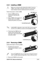
... Follow these steps to remove a DIMM. 1. Support the DIMM lightly with a notch so that the notch on the DIMM matches the break on the socket. ASUS PC-DL Deluxe motherboard 2-13 Follow these steps to install a DIMM. 1. Firmly insert the DIMM into a socket to both the motherboard and the components. Align a DIMM on the...
... Follow these steps to remove a DIMM. 1. Support the DIMM lightly with a notch so that the notch on the DIMM matches the break on the socket. ASUS PC-DL Deluxe motherboard 2-13 Follow these steps to install a DIMM. 1. Firmly insert the DIMM into a socket to both the motherboard and the components. Align a DIMM on the...

User Guide
Page 41
Otherwise, conflicts will arise between the two PCI groups, making the system unstable and the card inoperable. ASUS PC-DL Deluxe motherboard 2-15 When using PCI cards on shared slots, ensure that the drivers support "Share IRQ" or that the cards do not need IRQ assignments. ...
Otherwise, conflicts will arise between the two PCI groups, making the system unstable and the card inoperable. ASUS PC-DL Deluxe motherboard 2-15 When using PCI cards on shared slots, ensure that the drivers support "Share IRQ" or that the cards do not need IRQ assignments. ...
User Guide
Page 43
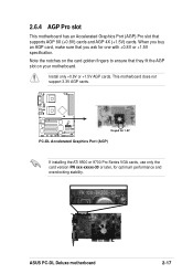
ASUS PC-DL Deluxe motherboard 2-17 This motherboard does not support 3.3V AGP cards. Note the notches on the card golden fingers to ensure that supports AGP 8X (+0.8V) ... and AGP 4X (+1.5V) cards. When you buy an AGP card, make sure that you ask for optimum performance and overclocking stability. Keyed for 1.5V PC-DL PC-DL Accelerated Graphics Port (AGP) If installing the ATi 9500 or 9700 Pro Series VGA cards, use only the card version PN xxx-xxxxx-30 or...
ASUS PC-DL Deluxe motherboard 2-17 This motherboard does not support 3.3V AGP cards. Note the notches on the card golden fingers to ensure that supports AGP 8X (+0.8V) ... and AGP 4X (+1.5V) cards. When you buy an AGP card, make sure that you ask for optimum performance and overclocking stability. Keyed for 1.5V PC-DL PC-DL Accelerated Graphics Port (AGP) If installing the ATi 9500 or 9700 Pro Series VGA cards, use only the card version PN xxx-xxxxx-30 or...
User Guide
Page 45
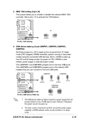
...USBPWR4 jumpers are for the rear USB ports. ASUS PC-DL Deluxe motherboard 2-19 IEEE 1394 setting (3-pin J4) This jumper allows you can provide 500mA on the +5VSB lead for the internal USB headers that you to activate the 1394 feature. PC-DL PC-DL 1394 Setting J4 12 23 Enable (Default) ... power mode) using the connected USB devices. USBPW1 2 1 +5V (Default) 3 2 +5VSB USBPW2 2 1 +5V (Default) 3 2 +5VSB USBPW3 USBPW4 12 23 PC-DL PC-DL USB Device Wake Up +5V (Default) +5VSB 1. Set to +5VSB to CPU, DRAM in slow refresh, power supply in sleep mode. USB device wake-up...
...USBPWR4 jumpers are for the rear USB ports. ASUS PC-DL Deluxe motherboard 2-19 IEEE 1394 setting (3-pin J4) This jumper allows you can provide 500mA on the +5VSB lead for the internal USB headers that you to activate the 1394 feature. PC-DL PC-DL 1394 Setting J4 12 23 Enable (Default) ... power mode) using the connected USB devices. USBPW1 2 1 +5V (Default) 3 2 +5VSB USBPW2 2 1 +5V (Default) 3 2 +5VSB USBPW3 USBPW4 12 23 PC-DL PC-DL USB Device Wake Up +5V (Default) +5VSB 1. Set to +5VSB to CPU, DRAM in slow refresh, power supply in sleep mode. USB device wake-up...
User Guide
Page 47
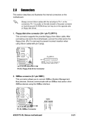
... (System Management Bus) devices. FLOPPY1 PIN 1 NOTE: Orient the red markings on floppy disk drives. 1. PC-DL PC-DL SMBus Connector SMB1 1 ASUS PC-DL Deluxe motherboard FLOATING SMBCLK Ground SMBDATA +3V 2-21 After connecting one end to Pin 1 on the motherboard. PC-DL PC-DL Floppy Disk Drive Connector 2. Always connect ribbon cables with the red stripe to the motherboard, connect...
... (System Management Bus) devices. FLOPPY1 PIN 1 NOTE: Orient the red markings on floppy disk drives. 1. PC-DL PC-DL SMBus Connector SMB1 1 ASUS PC-DL Deluxe motherboard FLOATING SMBCLK Ground SMBDATA +3V 2-21 After connecting one end to Pin 1 on the motherboard. PC-DL PC-DL Floppy Disk Drive Connector 2. Always connect ribbon cables with the red stripe to the motherboard, connect...
User Guide
Page 49
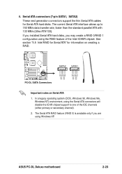
...allows up to one of the Intel ICH5R chipset. GND RSATA_TXP2 RSATA_TXN2 GND RSATA_RXP2 RSATA_RXN2 GND GND RSATA_TXP1 RSATA_TXN1 GND RSATA_RXP1 RSATA_RXN1 GND ASUS PC-DL Deluxe motherboard 2-23 In a legacy operating system (DOS, Windows 98, Windows Me, Windows NT) environment, using the Serial ATA ...support to 150 MB/s data transfer rate, faster than the standard parallel ATA with 133 MB/s (Ultra ATA/133). SATA2 SATA1 PC-DL PC-DL SATA Connectors Important notes on creating a RAID. Serial ATA connectors (7-pin SATA1, SATA2) These next generation connectors support the thin ...
...allows up to one of the Intel ICH5R chipset. GND RSATA_TXP2 RSATA_TXN2 GND RSATA_RXP2 RSATA_RXN2 GND GND RSATA_TXP1 RSATA_TXN1 GND RSATA_RXP1 RSATA_RXN1 GND ASUS PC-DL Deluxe motherboard 2-23 In a legacy operating system (DOS, Windows 98, Windows Me, Windows NT) environment, using the Serial ATA ...support to 150 MB/s data transfer rate, faster than the standard parallel ATA with 133 MB/s (Ultra ATA/133). SATA2 SATA1 PC-DL PC-DL SATA Connectors Important notes on creating a RAID. Serial ATA connectors (7-pin SATA1, SATA2) These next generation connectors support the thin ...
User Guide
Page 51
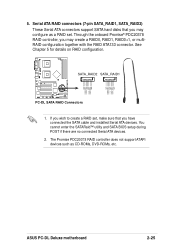
.... Through the onboard Promise® PDC20378 RAID controller, you may create a RAID0, RAID1, RAID0+1, or multiRAID configuration together with the RAID ATA133 connector. SATA_RAID2 SATA_RAID1 PC-DL PC-DL SATA RAID Connectors 1. Serial ATA RAID connectors (7-pin SATA_RAID1, SATA_RAID2) These Serial ATA connectors support SATA hard disks that you wish to create a RAID set... sure that you may configure as CD-ROMs, DVD-ROMs, etc. GND RSATA_TXP2 RSATA_TXN2 GND RSATA_RXP2 RSATA_RXN2 GND GND RSATA_TXP1 RSATA_TXN1 GND RSATA_RXP1 RSATA_RXN1 GND ASUS PC-DL Deluxe motherboard 2-25
.... Through the onboard Promise® PDC20378 RAID controller, you may create a RAID0, RAID1, RAID0+1, or multiRAID configuration together with the RAID ATA133 connector. SATA_RAID2 SATA_RAID1 PC-DL PC-DL SATA RAID Connectors 1. Serial ATA RAID connectors (7-pin SATA_RAID1, SATA_RAID2) These Serial ATA connectors support SATA hard disks that you wish to create a RAID set... sure that you may configure as CD-ROMs, DVD-ROMs, etc. GND RSATA_TXP2 RSATA_TXN2 GND RSATA_RXP2 RSATA_RXN2 GND GND RSATA_TXP1 RSATA_TXN1 GND RSATA_RXP1 RSATA_RXN1 GND ASUS PC-DL Deluxe motherboard 2-25


