
User Manual
Page 22
... (20-1 pin USB3_56) 10. Digital audio connector (4-1 pin SPDIF_OUT) 18. Front panel audio connector (10-1 pin AAFP) Page Chapter 2 ASUS P8Z77-V LX 2-3 Intel® Z77 Serial ATA 6.0 Gb/s connectors (7-pin SATA6G_1/2 [gray]) 13. Clear RTC RAM (3-pin CLRTC) 15. Intel® Z77 Serial ATA 3.0 Gb/s connectors (7-pin SATA3G_1-4 [blue]) 12. USB connectors (10-1 pin...
... (20-1 pin USB3_56) 10. Digital audio connector (4-1 pin SPDIF_OUT) 18. Front panel audio connector (10-1 pin AAFP) Page Chapter 2 ASUS P8Z77-V LX 2-3 Intel® Z77 Serial ATA 6.0 Gb/s connectors (7-pin SATA6G_1/2 [gray]) 13. Clear RTC RAM (3-pin CLRTC) 15. Intel® Z77 Serial ATA 3.0 Gb/s connectors (7-pin SATA3G_1-4 [blue]) 12. USB connectors (10-1 pin...
User Manual
Page 34
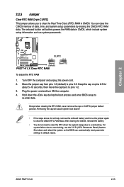
...the cap on pins 2-3 for about 5-10 seconds, then move the jumper again to clear the CMOS RTC RAM data. P8Z77-V LX CLRTC 12 23 Normal (Default) P8Z77-V LX Clear RTC RAM Clear RTC To erase the RTC RAM 1. Plug the power cord and turn ON the computer. 4. Shut down the key during the boot process ...boot failure! • If the steps above do not need to clear the RTC when the system hangs due to pins 1-2. 3. ASUS P8Z77-V LX 2-15 The onboard button cell battery powers the RAM data in CMOS. Hold down and reboot the system so the BIOS can clear the CMOS memory of date, time, and...
...the cap on pins 2-3 for about 5-10 seconds, then move the jumper again to clear the CMOS RTC RAM data. P8Z77-V LX CLRTC 12 23 Normal (Default) P8Z77-V LX Clear RTC RAM Clear RTC To erase the RTC RAM 1. Plug the power cord and turn ON the computer. 4. Shut down the key during the boot process ...boot failure! • If the steps above do not need to clear the RTC when the system hangs due to pins 1-2. 3. ASUS P8Z77-V LX 2-15 The onboard button cell battery powers the RAM data in CMOS. Hold down and reboot the system so the BIOS can clear the CMOS memory of date, time, and...
User Manual
Page 62
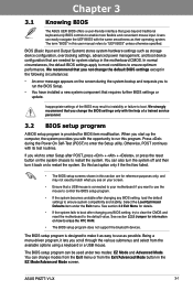
...BIOS setup program. • If the system becomes unstable after changing any BIOS setting, load the default settings to erase the RTC RAM. • The BIOS setup program does not support the bluetooth devices. We strongly recommend that you change modes from the Exit ...easily navigate the UEFI BIOS with its test routines. Select the Load Optimized Defaults item under two modes: EZ Mode and Advanced Mode. Chapter 3 ASUS P8Z77-V LX 3-1 Inappropriate settings of a trained service personnel. 3.2 BIOS setup program A BIOS setup program is connected to your screen. • Ensure that a...
...BIOS setup program. • If the system becomes unstable after changing any BIOS setting, load the default settings to erase the RTC RAM. • The BIOS setup program does not support the bluetooth devices. We strongly recommend that you change modes from the Exit ...easily navigate the UEFI BIOS with its test routines. Select the Load Optimized Defaults item under two modes: EZ Mode and Advanced Mode. Chapter 3 ASUS P8Z77-V LX 3-1 Inappropriate settings of a trained service personnel. 3.2 BIOS setup program A BIOS setup program is connected to your screen. • Ensure that a...
User Manual
Page 66
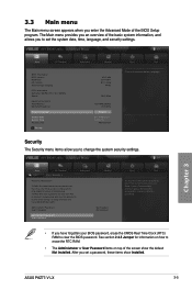
..., erase the CMOS Real Time Clock (RTC) RAM to erase the RTC RAM. • The Administrator or User Password items on password and must be entered to Setup and is only asked for information on how to clear the BIOS password. EFI BIOS Utility - Chapter 3 ASUS P8Z77-V LX 3-5 After you have Administrator rights Administrator Password...
..., erase the CMOS Real Time Clock (RTC) RAM to erase the RTC RAM. • The Administrator or User Password items on password and must be entered to Setup and is only asked for information on how to clear the BIOS password. EFI BIOS Utility - Chapter 3 ASUS P8Z77-V LX 3-5 After you have Administrator rights Administrator Password...


