User Manual
Page 13
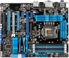
... 1 x 2-in the long line of the above items is damaged or missing, contact your retailer. • The illustrated items above are for buying an ASUS® P8Z68-V PRO/GEN3 motherboard! ASUS P8Z68-V PRO/GEN3 1-1 Chapter 1 Chapter 1: Chapter 1 Product introduction 1.1 Welcome! The motherboard delivers a host of new features and latest technologies, making it , check the items in your package...
... 1 x 2-in the long line of the above items is damaged or missing, contact your retailer. • The illustrated items above are for buying an ASUS® P8Z68-V PRO/GEN3 motherboard! ASUS P8Z68-V PRO/GEN3 1-1 Chapter 1 Chapter 1: Chapter 1 Product introduction 1.1 Welcome! The motherboard delivers a host of new features and latest technologies, making it , check the items in your package...
User Manual
Page 15
...(O.C.) / 1600 / 1333 / 1066 Support The motherboard supports DDR3 memory that features data transfer rates of 2200(O.C.) / 2133(O.C.) / 1866 / 1600/ 1333 / 1066 MHz to a digital standard. ASUS P8Z68-V PRO/GEN3 1-3 New generation Dual Intelligent Processors 2 with DIGI+ VRM digital power design launch control into a new era, empowering users with DIGI+ VRM The world's first Dual...
...(O.C.) / 1600 / 1333 / 1066 Support The motherboard supports DDR3 memory that features data transfer rates of 2200(O.C.) / 2133(O.C.) / 1866 / 1600/ 1333 / 1066 MHz to a digital standard. ASUS P8Z68-V PRO/GEN3 1-3 New generation Dual Intelligent Processors 2 with DIGI+ VRM digital power design launch control into a new era, empowering users with DIGI+ VRM The world's first Dual...

User Manual
Page 17
...setup sharing is for experienced performance enthusiasts that goes beyond traditional keyboard-only BIOS controls to install. ASUS Q-Design ASUS Q-Design enhances your motherboard against static electricity and shields it against Electronic Magnetic Interference (EMI). making...ASUS Q-Shield The specially designed ASUS Q-Shield does without using a bootable floppy disk or an OS-based utility. Users can easily navigate the UEFI BIOS with full storage space utilization helping deliver far more intricate system control, including detailed DRAM information. ASUS P8Z68-V PRO/GEN3...
...setup sharing is for experienced performance enthusiasts that goes beyond traditional keyboard-only BIOS controls to install. ASUS Q-Design ASUS Q-Design enhances your motherboard against static electricity and shields it against Electronic Magnetic Interference (EMI). making...ASUS Q-Shield The specially designed ASUS Q-Shield does without using a bootable floppy disk or an OS-based utility. Users can easily navigate the UEFI BIOS with full storage space utilization helping deliver far more intricate system control, including detailed DRAM information. ASUS P8Z68-V PRO/GEN3...

User Manual
Page 19
... you install or remove any component, ensure that the ATX power supply is switched off or the power cord is detached from the power supply. ASUS P8Z68-V PRO/GEN3 2-1 Chapter 2: Chapter 2 Hardware information 2.1 Before you proceed Take note of the following precautions before touching any component. • Before handling components, use a grounded wrist strap...
... you install or remove any component, ensure that the ATX power supply is switched off or the power cord is detached from the power supply. ASUS P8Z68-V PRO/GEN3 2-1 Chapter 2: Chapter 2 Hardware information 2.1 Before you proceed Take note of the following precautions before touching any component. • Before handling components, use a grounded wrist strap...

User Manual
Page 23
A DDR3 module is notched differently from a DDR or DDR2 module. 2.2.3 System memory The motherboard comes with four Double Data Rate 3 (DDR3) Dual Inline Memory Modules (DIMM) slots. DO NOT install a DDR or DDR2 memory module to the DDR3 slot. Recommended memory configurations Chapter 2 ASUS P8Z68-V PRO/GEN3 2-5
A DDR3 module is notched differently from a DDR or DDR2 module. 2.2.3 System memory The motherboard comes with four Double Data Rate 3 (DDR3) Dual Inline Memory Modules (DIMM) slots. DO NOT install a DDR or DDR2 memory module to the DDR3 slot. Recommended memory configurations Chapter 2 ASUS P8Z68-V PRO/GEN3 2-5
User Manual
Page 25
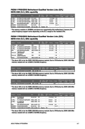
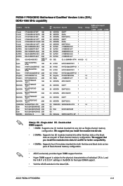
...DS Brand NO. G.SKILL F3-17600CL8D-4GBPS(XMP) 4GB(2 x 2GB) DS - - Voltage 1.65 1.65 1.65 1.65 1.5~1.7 - Vendors Part No. P8Z68-V PRO/GEN3 Motherboard Qualified Vendors Lists (QVL) DDR3-2133 (O.C.) MHz capability Vendors CORSAIR G.SKILL G.SKILL GEIL Transcend Transcend Patriot Part No. Timing Voltage - 1.65 DIMM ...run at DDR3 2133 MHz frequency.. Size SS/ Chip Chip DS Brand NO. G.SKILL F3-17600CL9D-4GBTDS(XMP) 4GB(2 x 2GB) DS - - ASUS P8Z68-V PRO/GEN3 2-7 KINGMAX FLKE85F-B8KHA(XMP) 4G ( 2x 2G ) DS - - Due to CPU behavior, DDR3 2333 MHz memory module will run at DDR3 ...
...DS Brand NO. G.SKILL F3-17600CL8D-4GBPS(XMP) 4GB(2 x 2GB) DS - - Voltage 1.65 1.65 1.65 1.65 1.5~1.7 - Vendors Part No. P8Z68-V PRO/GEN3 Motherboard Qualified Vendors Lists (QVL) DDR3-2133 (O.C.) MHz capability Vendors CORSAIR G.SKILL G.SKILL GEIL Transcend Transcend Patriot Part No. Timing Voltage - 1.65 DIMM ...run at DDR3 2133 MHz frequency.. Size SS/ Chip Chip DS Brand NO. G.SKILL F3-17600CL9D-4GBTDS(XMP) 4GB(2 x 2GB) DS - - ASUS P8Z68-V PRO/GEN3 2-7 KINGMAX FLKE85F-B8KHA(XMP) 4G ( 2x 2G ) DS - - Due to CPU behavior, DDR3 2333 MHz memory module will run at DDR3 ...
User Manual
Page 29
...-10 1GB SS/ DS Chip Brand Chip NO. We suggest that you install the modules into slots A2 and B2 for the latest QVL. or D.O.C.P. ASUS P8Z68-V PRO/GEN3 2-11 DIMM socket support (Optional) 1 DIMM 2 DIMM 4 DIMM • • • • • • • • • • • • • • • • •...
...-10 1GB SS/ DS Chip Brand Chip NO. We suggest that you install the modules into slots A2 and B2 for the latest QVL. or D.O.C.P. ASUS P8Z68-V PRO/GEN3 2-11 DIMM socket support (Optional) 1 DIMM 2 DIMM 4 DIMM • • • • • • • • • • • • • • • • •...

User Manual
Page 31
... - shared - - - shared - - - - shared - - - 2-13 PCIEx1_1 - - PCI_1 - - LAN_1 - - - shared - - 1394 Controller - I.G.D. (Internal Graphics Device) shared - - - - - shared - - - - - - - - shared - - HD Audio - - - - - - ASUS P8Z68-V PRO/GEN3 G H - - - - - - - - - - - - - - - - - PCIEx16_2 shared - - - - - Marvell® SATA 6G Controller - - - IRQ assignments for details. PCIEx1_2/USB3_1234 - PCI_2 - - - USB 2.0 Controller 1 - - - - - - See page 2-26 for this motherboard...
... - shared - - - shared - - - - shared - - - 2-13 PCIEx1_1 - - PCI_1 - - LAN_1 - - - shared - - 1394 Controller - I.G.D. (Internal Graphics Device) shared - - - - - shared - - - - - - - - shared - - HD Audio - - - - - - ASUS P8Z68-V PRO/GEN3 G H - - - - - - - - - - - - - - - - - PCIEx16_2 shared - - - - - Marvell® SATA 6G Controller - - - IRQ assignments for details. PCIEx1_2/USB3_1234 - PCI_2 - - - USB 2.0 Controller 1 - - - - - - See page 2-26 for this motherboard...
User Manual
Page 33
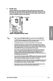
... location of failsafe settings. A messgae will appear during the tuning process, the system continues memory tuning after turning on the ASUS website at www.asus.com. • If you download and update to boot after using the MemOK! switch lights continuously. If the installed DIMMs...with ones recommended in the Memory QVL (Qualified Vendors Lists) in this user manual or on the computer. function. • The MemOK! ASUS P8Z68-V PRO/GEN3 2-15 Press and hold the MemOK! switch does not function under Windows™ OS environment. • During the tuning process, the system...
... location of failsafe settings. A messgae will appear during the tuning process, the system continues memory tuning after turning on the ASUS website at www.asus.com. • If you download and update to boot after using the MemOK! switch lights continuously. If the installed DIMMs...with ones recommended in the Memory QVL (Qualified Vendors Lists) in this user manual or on the computer. function. • The MemOK! ASUS P8Z68-V PRO/GEN3 2-15 Press and hold the MemOK! switch does not function under Windows™ OS environment. • During the tuning process, the system...
User Manual
Page 35
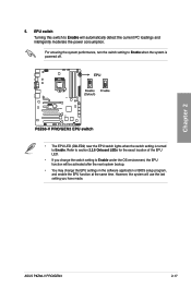
... Enable when the system is powered off. • The EPU LED (O2LED2) near the EPU switch lights when the switch setting is turned to Enable. ASUS P8Z68-V PRO/GEN3 2-17 Chapter 2 5.
... Enable when the system is powered off. • The EPU LED (O2LED2) near the EPU switch lights when the switch setting is turned to Enable. ASUS P8Z68-V PRO/GEN3 2-17 Chapter 2 5.
User Manual
Page 37
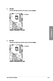
Chapter 2 ASUS P8Z68-V PRO/GEN3 2-19 3. EPU LED The EPU LED lights when the EPU switch is turned to Enable. TPU LED The TPU LED lights when the TPU switch is turned to Enable. 4.
Chapter 2 ASUS P8Z68-V PRO/GEN3 2-19 3. EPU LED The EPU LED lights when the EPU switch is turned to Enable. TPU LED The TPU LED lights when the TPU switch is turned to Enable. 4.
User Manual
Page 39
.... • When using Windows® XP SP3 or later versions. If you intend to create a Serial ATA RAID set using Serial ATA hard disk drives. ASUS P8Z68-V PRO/GEN3 2-21 The Serial ATA RAID feature is available only if you can create a RAID 0, 1, 5, and 10 configuration with the Intel® Rapid Storage Technology through...
.... • When using Windows® XP SP3 or later versions. If you intend to create a Serial ATA RAID set using Serial ATA hard disk drives. ASUS P8Z68-V PRO/GEN3 2-21 The Serial ATA RAID feature is available only if you can create a RAID 0, 1, 5, and 10 configuration with the Intel® Rapid Storage Technology through...
User Manual
Page 41
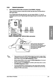
... 3.0 ports, and complies with this connector to section 3.5.6 Onboard Devices Configuration for data drives only. Refer to obtain the front panel USB 3.0 solution. ASUS P8Z68-V PRO/GEN3 2-23 3. You can connect the ASUS front panel USB 3.0 bracket to this USB 3.0 connector, you can have a front panel USB 3.0 solution. Marvell® Serial ATA 6.0 Gb/s connectors (7-pin...
... 3.0 ports, and complies with this connector to section 3.5.6 Onboard Devices Configuration for data drives only. Refer to obtain the front panel USB 3.0 solution. ASUS P8Z68-V PRO/GEN3 2-23 3. You can connect the ASUS front panel USB 3.0 bracket to this USB 3.0 connector, you can have a front panel USB 3.0 solution. Marvell® Serial ATA 6.0 Gb/s connectors (7-pin...
User Manual
Page 43
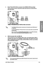
... the module to a slot opening at the back of the system chassis. IE1394_2) These connectors are for an additional Sony/Philips Digital Interface (S/PDIF) port(s). ASUS P8Z68-V PRO/GEN3 2-25 The S/PDIF module is purchased separately.
... the module to a slot opening at the back of the system chassis. IE1394_2) These connectors are for an additional Sony/Philips Digital Interface (S/PDIF) port(s). ASUS P8Z68-V PRO/GEN3 2-25 The S/PDIF module is purchased separately.

User Manual
Page 45
... a chassis-mounted front panel audio I /O module cable to this connector. • We recommend that supports either HD Audio or legacy AC`97 audio standard. Chapter 2 ASUS P8Z68-V PRO/GEN3 2-27
... a chassis-mounted front panel audio I /O module cable to this connector. • We recommend that supports either HD Audio or legacy AC`97 audio standard. Chapter 2 ASUS P8Z68-V PRO/GEN3 2-27

User Manual
Page 47
... reset button for the HDD Activity LED. The system power LED lights up or flashes when data is read from or written to this connector. ASUS P8Z68-V PRO/GEN3 2-29 Chapter 2 • System power LED (2-pin PLED) This 2-pin connector is for system reboot without turning off mode depending on the system power, and...
... reset button for the HDD Activity LED. The system power LED lights up or flashes when data is read from or written to this connector. ASUS P8Z68-V PRO/GEN3 2-29 Chapter 2 • System power LED (2-pin PLED) This 2-pin connector is for system reboot without turning off mode depending on the system power, and...

User Manual
Page 49
A B 2 3 ASUS P8Z68-V PRO/GEN3 2-31 Chapter 2 2.3.2 1 CPU installation The LGA1156 CPU is incompatible with the LGA1155 socket. DO NOT install a LGA1156 CPU on the LGA1155 socket.
A B 2 3 ASUS P8Z68-V PRO/GEN3 2-31 Chapter 2 2.3.2 1 CPU installation The LGA1156 CPU is incompatible with the LGA1155 socket. DO NOT install a LGA1156 CPU on the LGA1155 socket.
User Manual
Page 51
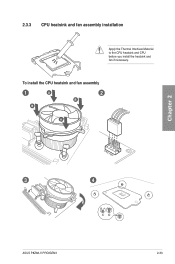
To install the CPU heatsink and fan assembly 1 A B 2 B A 3 4 ASUS P8Z68-V PRO/GEN3 2-33 Chapter 2 2.3.3 CPU heatsink and fan assembly installation Apply the Thermal Interface Material to the CPU heatsink and CPU before you install the heatsink and fan if necessary.
To install the CPU heatsink and fan assembly 1 A B 2 B A 3 4 ASUS P8Z68-V PRO/GEN3 2-33 Chapter 2 2.3.3 CPU heatsink and fan assembly installation Apply the Thermal Interface Material to the CPU heatsink and CPU before you install the heatsink and fan if necessary.

User Manual
Page 53
2.3.4 1 DIMM installation 2 Chapter 2 3 To remove a DIMM B A ASUS P8Z68-V PRO/GEN3 2-35
2.3.4 1 DIMM installation 2 Chapter 2 3 To remove a DIMM B A ASUS P8Z68-V PRO/GEN3 2-35
User Manual
Page 55
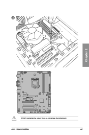
3 Chapter 2 DO NOT overtighten the screws! ASUS P8Z68-V PRO/GEN3 2-37 Doing so can damage the motherboard.
3 Chapter 2 DO NOT overtighten the screws! ASUS P8Z68-V PRO/GEN3 2-37 Doing so can damage the motherboard.


