User Manual
Page 13
... below. 1.2 Package contents Check your retailer. • The illustrated items above are for reference only. ASUS P8H67-M EVO 1-1 Before you for the following items. User Manual ASUS P8H67-M EVO motherboard User guide Support DVD 2 x Serial ATA 6.0Gb/s cables 2 x Serial ATA 3.0Gb/s cables 1 x ASUS I/O Shield Ultra DMA 133/ 100/66 cable 1 x 2-port USB 2.0 / 1-port eSATA module 1 x 2-in the...
... below. 1.2 Package contents Check your retailer. • The illustrated items above are for reference only. ASUS P8H67-M EVO 1-1 Before you for the following items. User Manual ASUS P8H67-M EVO motherboard User guide Support DVD 2 x Serial ATA 6.0Gb/s cables 2 x Serial ATA 3.0Gb/s cables 1 x ASUS I/O Shield Ultra DMA 133/ 100/66 cable 1 x 2-port USB 2.0 / 1-port eSATA module 1 x 2-in the...
User Manual
Page 15
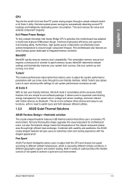
...system power savings by different climate conditions in -one simple to switch back and forth between different utilities. 1.3.3 ASUS Quiet Thermal Solutions ASUS Fanless Design-Heat-sink solution The crystal-shaped heatsink features 0-dB thermal solution that offers users a noiseless PC ... to use functions, with just a few clicks through its fast user-friendly interface, ASUS AI Suite II consolidates all -in different geographic regions and system loading. ASUS P8H67-M EVO 1-3 MemOK! AI Suite II With its user-friendly interface. determines failsafe settings and dramatically...
...system power savings by different climate conditions in -one simple to switch back and forth between different utilities. 1.3.3 ASUS Quiet Thermal Solutions ASUS Fanless Design-Heat-sink solution The crystal-shaped heatsink features 0-dB thermal solution that offers users a noiseless PC ... to use functions, with just a few clicks through its fast user-friendly interface, ASUS AI Suite II consolidates all -in different geographic regions and system loading. ASUS P8H67-M EVO 1-3 MemOK! AI Suite II With its user-friendly interface. determines failsafe settings and dramatically...
User Manual
Page 17
... wall socket before touching any component, ensure that the ATX power supply is switched off or the power cord is detached from the power supply. ASUS P8H67-M EVO 2-1 Failure to do so may cause severe damage to avoid touching the ICs on them. • Whenever you uninstall any component, place it on a grounded...
... wall socket before touching any component, ensure that the ATX power supply is switched off or the power cord is detached from the power supply. ASUS P8H67-M EVO 2-1 Failure to do so may cause severe damage to avoid touching the ICs on them. • Whenever you uninstall any component, place it on a grounded...
User Manual
Page 21
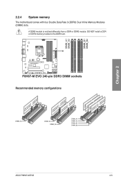
DO NOT install a DDR or DDR2 memory module to the DDR3 slot. 2.2.4 System memory The motherboard comes with four Double Data Rate 3 (DDR3) Dual Inline Memory Modules (DIMM) slots. A DDR3 module is notched differently from a DDR or DDR2 module. Recommended memory configurations Chapter 2 ASUS P8H67-M EVO 2-5
DO NOT install a DDR or DDR2 memory module to the DDR3 slot. 2.2.4 System memory The motherboard comes with four Double Data Rate 3 (DDR3) Dual Inline Memory Modules (DIMM) slots. A DDR3 module is notched differently from a DDR or DDR2 module. Recommended memory configurations Chapter 2 ASUS P8H67-M EVO 2-5
User Manual
Page 27
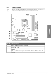
2.2.5 Expansion slots Ensure to do so may cause you physical injury and damage motherboard components. Chapter 2 Slot No. Slot Description 1 PCIe 2.0 x16_1 slot [blue] (at x16 mode) 2 PCIe 2.0 x1_1 slot 3 PCI slot 4 PCIe 2.0 x16_2 slot [black] (at x4 mode, compatible with PCIe x1, x2 and x4 devices) ASUS P8H67-M EVO 2-11 Failure to unplug the power cord before adding or removing expansion cards.
2.2.5 Expansion slots Ensure to do so may cause you physical injury and damage motherboard components. Chapter 2 Slot No. Slot Description 1 PCIe 2.0 x16_1 slot [blue] (at x16 mode) 2 PCIe 2.0 x1_1 slot 3 PCI slot 4 PCIe 2.0 x16_2 slot [black] (at x4 mode, compatible with PCIe x1, x2 and x4 devices) ASUS P8H67-M EVO 2-11 Failure to unplug the power cord before adding or removing expansion cards.
User Manual
Page 29
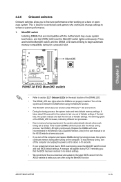
...of failsafe settings. Replace the DIMMs with ones recommended in the Memory QVL (Qualified Vendors Lists) in this user manual or on the ASUS website at www.asus.com after using the MemOK! Chapter 2 • Refer to section 2.2.7 Onboard LEDs for the system to test one set of the...• If your system fail to boot due to BIOS overclocking, press the MemOK! ASUS P8H67-M EVO 2-13 switch Installing DIMMs that you download and update to the latest BIOS version from the ASUS website at www.asus.com. • If you turn off the computer and replace DIMMs during POST reminding ...
...of failsafe settings. Replace the DIMMs with ones recommended in the Memory QVL (Qualified Vendors Lists) in this user manual or on the ASUS website at www.asus.com after using the MemOK! Chapter 2 • Refer to section 2.2.7 Onboard LEDs for the system to test one set of the...• If your system fail to boot due to BIOS overclocking, press the MemOK! ASUS P8H67-M EVO 2-13 switch Installing DIMMs that you download and update to the latest BIOS version from the ASUS website at www.asus.com. • If you turn off the computer and replace DIMMs during POST reminding ...
User Manual
Page 31
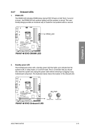
This is solved. Chapter 2 ASUS P8H67-M EVO 2-15 If an error is found , the DRAM LED will continue lighting until the problem is a reminder that you should shut down the system and ...
This is solved. Chapter 2 ASUS P8H67-M EVO 2-15 If an error is found , the DRAM LED will continue lighting until the problem is a reminder that you should shut down the system and ...
User Manual
Page 33
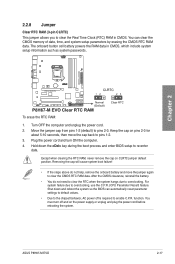
... 1-2. 3. Except when clearing the RTC RAM, never remove the cap on the power supply or unplug and plug the power cord before rebooting the system. ASUS P8H67-M EVO 2-17 Plug the power cord and turn off is required to overclocking. After the CMOS clearance, reinstall the battery. • You do not help, remove...
... 1-2. 3. Except when clearing the RTC RAM, never remove the cap on the power supply or unplug and plug the power cord before rebooting the system. ASUS P8H67-M EVO 2-17 Plug the power cord and turn off is required to overclocking. After the CMOS clearance, reinstall the battery. • You do not help, remove...
User Manual
Page 35
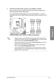
... Storage Technology through the onboard Intel® H67 chipset. • These connectors are using these connectors, set using Windows® XP SP2 or later versions. ASUS P8H67-M EVO 2-19 Refer to section 3.5.5 SATA Configuration for details. • You must install Windows® XP Service Pack 2 or later versions before using hot-plug and...
... Storage Technology through the onboard Intel® H67 chipset. • These connectors are using these connectors, set using Windows® XP SP2 or later versions. ASUS P8H67-M EVO 2-19 Refer to section 3.5.5 SATA Configuration for details. • You must install Windows® XP Service Pack 2 or later versions before using hot-plug and...
User Manual
Page 37
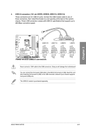
The USB 2.0 module is purchased separately. ASUS P8H67-M EVO 2-21 Doing so will damage the motherboard! Chapter 2 Never connect a 1394 cable to a slot opening at the back of these connectors, then install the module ...to the USB connectors. Connect the USB module cable to any of the system chassis. 4. You can connect the front panel USB cable to the ASUS Q-Connector (USB, blue) first, and then install the Q-Connector (USB) to 480 Mbps connection speed. USB 2.0 connectors (10-1 pin USB78, USB910, USB1112, USB1314) These connectors...
The USB 2.0 module is purchased separately. ASUS P8H67-M EVO 2-21 Doing so will damage the motherboard! Chapter 2 Never connect a 1394 cable to a slot opening at the back of these connectors, then install the module ...to the USB connectors. Connect the USB module cable to any of the system chassis. 4. You can connect the front panel USB cable to the ASUS Q-Connector (USB, blue) first, and then install the Q-Connector (USB) to 480 Mbps connection speed. USB 2.0 connectors (10-1 pin USB78, USB910, USB1112, USB1314) These connectors...
User Manual
Page 39
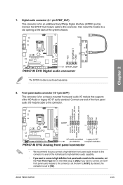
... 2 The S/PDIF module is for an additional Sony/Philips Digital Interface (S/PDIF) port(s). Front panel audio connector (10-1 pin AAFP) This connector is purchased separately. 8. ASUS P8H67-M EVO 2-23 if you connect a high-definition front panel audio module to this connector, then install the module to [AC97]. By default, this connector, set to...
... 2 The S/PDIF module is for an additional Sony/Philips Digital Interface (S/PDIF) port(s). Front panel audio connector (10-1 pin AAFP) This connector is purchased separately. 8. ASUS P8H67-M EVO 2-23 if you connect a high-definition front panel audio module to this connector, then install the module to [AC97]. By default, this connector, set to...
User Manual
Page 41
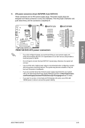
... connect the 8-pin EATX12 V power plug; com/PowerSupplyCalculator/PSCalculator.aspx?SLanguage=en-us for your system, refer to fit these connectors in only one orientation. ASUS P8H67-M EVO 2-25 The power supply plugs are for ATX power supply plugs. ATX power connectors (24-pin EATXPWR; 8-pin EATX12V) These connectors are designed to the...
... connect the 8-pin EATX12 V power plug; com/PowerSupplyCalculator/PSCalculator.aspx?SLanguage=en-us for your system, refer to fit these connectors in only one orientation. ASUS P8H67-M EVO 2-25 The power supply plugs are for ATX power supply plugs. ATX power connectors (24-pin EATXPWR; 8-pin EATX12V) These connectors are designed to the...
User Manual
Page 43
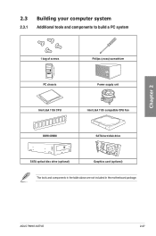
Chapter 2 2.3 Building your computer system 2.3.1 Additional tools and components to build a PC system 1 bag of screws Philips (cross) screwdriver PC chassis Power supply unit Intel LGA 1155 CPU Intel LGA 1155 compatible CPU Fan DDR3 DIMM SATA hard disk drive SATA optical disc drive (optional) Graphics card (optional) The tools and components in the table above are not included in the motherboard package. ASUS P8H67-M EVO 2-27
Chapter 2 2.3 Building your computer system 2.3.1 Additional tools and components to build a PC system 1 bag of screws Philips (cross) screwdriver PC chassis Power supply unit Intel LGA 1155 CPU Intel LGA 1155 compatible CPU Fan DDR3 DIMM SATA hard disk drive SATA optical disc drive (optional) Graphics card (optional) The tools and components in the table above are not included in the motherboard package. ASUS P8H67-M EVO 2-27
User Manual
Page 47
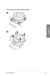
To uninstall the CPU heatsink and fan assembly 1 2 B A B A Chapter 2 ASUS P8H67-M EVO 2-31
To uninstall the CPU heatsink and fan assembly 1 2 B A B A Chapter 2 ASUS P8H67-M EVO 2-31

User Manual
Page 49
The motherboard layout may vary with models, but the installation steps remain the same. 2 Chapter 2 ASUS P8H67-M EVO 2-33 2.3.5 1 Motherboard installation The diagrams in this section are for reference only.
The motherboard layout may vary with models, but the installation steps remain the same. 2 Chapter 2 ASUS P8H67-M EVO 2-33 2.3.5 1 Motherboard installation The diagrams in this section are for reference only.
User Manual
Page 51
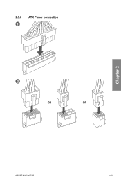
2.3.6 1 ATX Power connection 2 OR OR Chapter 2 ASUS P8H67-M EVO 2-35
2.3.6 1 ATX Power connection 2 OR OR Chapter 2 ASUS P8H67-M EVO 2-35

User Manual
Page 53
Chapter 2 2.3.8 Front I/O Connector To install ASUS Q-Connector 1 2 IDE_LED+ IDE_LED- IDE_LED PWR Ground Reset Ground POWER SW RESET SW To install USB 2.0 Connector To install front panel audio connector USB 2.0 AAFP ASUS P8H67-M EVO 2-37
Chapter 2 2.3.8 Front I/O Connector To install ASUS Q-Connector 1 2 IDE_LED+ IDE_LED- IDE_LED PWR Ground Reset Ground POWER SW RESET SW To install USB 2.0 Connector To install front panel audio connector USB 2.0 AAFP ASUS P8H67-M EVO 2-37
User Manual
Page 55
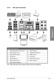
2.3.10 Rear panel connection Chapter 2 Rear panel connectors 1. PS/2 keyboard/mouse combo port 2. USB 3.0 ports 1 and 2 13. Power External SATA port 8. IEEE 1394a port 9. Optical S/PDIF Out port 4. Audio I/O ports*** *and **: Refer to the tables on the next page for LAN port and audio port definitions. DVI out pot 12. ASUS P8H67-M EVO 2-39 VGA out port 5. DisplayPort output port** 10. USB 2.0 ports 3 and 4 3. USB 2.0 ports 5 and 6 7. HDMI out port** 11. LAN (RJ-45) port* 6.
2.3.10 Rear panel connection Chapter 2 Rear panel connectors 1. PS/2 keyboard/mouse combo port 2. USB 3.0 ports 1 and 2 13. Power External SATA port 8. IEEE 1394a port 9. Optical S/PDIF Out port 4. Audio I/O ports*** *and **: Refer to the tables on the next page for LAN port and audio port definitions. DVI out pot 12. ASUS P8H67-M EVO 2-39 VGA out port 5. DisplayPort output port** 10. USB 2.0 ports 3 and 4 3. USB 2.0 ports 5 and 6 7. HDMI out port** 11. LAN (RJ-45) port* 6.
User Manual
Page 57
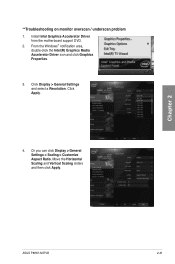
Click Apply. 4. Move the Horizontal Scaling and Vertical Scaling sliders and then click Apply. ASUS P8H67-M EVO 2-41 Click Display > General Settings and select a Resolution. From the Windows® notification area, double-click the Intel(R) Graphics Media Accelerator Driver icon and click Graphics Properties. 3. Or you can click Display > General Settings > Scaling > Customize Aspect Ratio. Chapter 2 **Troubleshooting on monitor overscan / underscan problem 1. Install Intel Graphics Accelerator Driver from the motherboard support DVD. 2.
Click Apply. 4. Move the Horizontal Scaling and Vertical Scaling sliders and then click Apply. ASUS P8H67-M EVO 2-41 Click Display > General Settings and select a Resolution. From the Windows® notification area, double-click the Intel(R) Graphics Media Accelerator Driver icon and click Graphics Properties. 3. Or you can click Display > General Settings > Scaling > Customize Aspect Ratio. Chapter 2 **Troubleshooting on monitor overscan / underscan problem 1. Install Intel Graphics Accelerator Driver from the motherboard support DVD. 2.
User Manual
Page 59
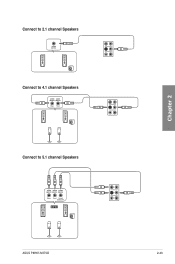
Connect to 2.1 channel Speakers Connect to 4.1 channel Speakers Connect to 5.1 channel Speakers Chapter 2 ASUS P8H67-M EVO 2-43
Connect to 2.1 channel Speakers Connect to 4.1 channel Speakers Connect to 5.1 channel Speakers Chapter 2 ASUS P8H67-M EVO 2-43


