
User Manual
Page 1
Motherboard P7H55-M LX/USB3
Motherboard P7H55-M LX/USB3

User Manual
Page 3
Contents Notices...v Safety information vi About this guide vi P7H55-M LX/USB3 specifications summary viii Chapter 1 Product introduction 1.1 Before you proceed 1-1 1.2 Motherboard overview 1-2 1.2.1 Motherboard layout 1-2 1.2.2 Layout contents 1-2 1.3 Central Processing Unit (CPU 1-3 1.4 System memory...1.8 Software support 1-15 1.8.1 Installing an operating system 1-15 1.8.2 Support DVD information 1-15 Chapter 2 BIOS information 2.1 Managing and updating your BIOS 2-1 2.1.1 ASUS Update 2-1 2.1.2 ASUS EZ Flash 2 2-2 2.1.3 ASUS BIOS Updater 2-3 2.1.4 ASUS CrashFree BIOS 3 2-6 iii
Contents Notices...v Safety information vi About this guide vi P7H55-M LX/USB3 specifications summary viii Chapter 1 Product introduction 1.1 Before you proceed 1-1 1.2 Motherboard overview 1-2 1.2.1 Motherboard layout 1-2 1.2.2 Layout contents 1-2 1.3 Central Processing Unit (CPU 1-3 1.4 System memory...1.8 Software support 1-15 1.8.1 Installing an operating system 1-15 1.8.2 Support DVD information 1-15 Chapter 2 BIOS information 2.1 Managing and updating your BIOS 2-1 2.1.1 ASUS Update 2-1 2.1.2 ASUS EZ Flash 2 2-2 2.1.3 ASUS BIOS Updater 2-3 2.1.4 ASUS CrashFree BIOS 3 2-6 iii

User Manual
Page 4
... 2.6 Boot menu 2-17 2.6.1 Boot Device Priority 2-17 2.6.2 Boot Settings Configuration 2-17 2.6.3 Security 2-18 2.7 Tools menu 2-19 2.7.1 AI NET 2 2-19 2.7.2 ASUS EZ Flash 2 2-19 2.7.3 IO Level up [Disabled 2-19 2.8 Exit menu 2-20 P7H55-M LX/USB3 motherboard installation notices 2-21 Intel® LGA1156 processor and chipset combination instruction... 2-21 Memory configuration 2-21 Configurations for the PCI...
... 2.6 Boot menu 2-17 2.6.1 Boot Device Priority 2-17 2.6.2 Boot Settings Configuration 2-17 2.6.3 Security 2-18 2.7 Tools menu 2-19 2.7.1 AI NET 2 2-19 2.7.2 ASUS EZ Flash 2 2-19 2.7.3 IO Level up [Disabled 2-19 2.8 Exit menu 2-20 P7H55-M LX/USB3 motherboard installation notices 2-21 Intel® LGA1156 processor and chipset combination instruction... 2-21 Memory configuration 2-21 Configurations for the PCI...

User Manual
Page 8
...® DirectX 10 - ASUS EZ Flash 2 - buffered memory * Refer to www.asus.com for Intel® CPU support list. We recommend a maximum of 4GB capacity or more, Windows® 32-bit operating system may only recognize less than 3GB. P7H55-M LX/USB3 specifications summary CPU Chipset Memory... Expansion slots VGA output Storage LAN Audio USB ASUS unique features LGA1156 socket for Intel® Core™ i7/ Core™ i5/ Core™...
...® DirectX 10 - ASUS EZ Flash 2 - buffered memory * Refer to www.asus.com for Intel® CPU support list. We recommend a maximum of 4GB capacity or more, Windows® 32-bit operating system may only recognize less than 3GB. P7H55-M LX/USB3 specifications summary CPU Chipset Memory... Expansion slots VGA output Storage LAN Audio USB ASUS unique features LGA1156 socket for Intel® Core™ i7/ Core™ i5/ Core™...

User Manual
Page 9
P7H55-M LX/ USB3 specifications summary Rear panel ports Internal connectors BIOS features Manageability Accessories Support DVD Form factor 1 x PS/2 Mouse port 1 x PS/2 Keyboard port 1 x D-Sub port 1 x DVI-D port 1 x ... v2.0, WfM 2.0, SM BIOS v2.5, ACPI v2.0a WOL, PXE, PME Wake up, WOR by Ring 2 x Serial ATA cables 1 x I/O shield 1 x User Manual 1 x Support DVD Drivers ASUS Utilities ASUS Update Anti-virus software (OEM version) uATX form factor: 9.6 in x 7.8 in (24.4 cm x 19.8 cm) * Specifications are subject to change without notice. ix
P7H55-M LX/ USB3 specifications summary Rear panel ports Internal connectors BIOS features Manageability Accessories Support DVD Form factor 1 x PS/2 Mouse port 1 x PS/2 Keyboard port 1 x D-Sub port 1 x DVI-D port 1 x ... v2.0, WfM 2.0, SM BIOS v2.5, ACPI v2.0a WOL, PXE, PME Wake up, WOR by Ring 2 x Serial ATA cables 1 x I/O shield 1 x User Manual 1 x Support DVD Drivers ASUS Utilities ASUS Update Anti-virus software (OEM version) uATX form factor: 9.6 in x 7.8 in (24.4 cm x 19.8 cm) * Specifications are subject to change without notice. ix

User Manual
Page 10
... touching the ICs on them due to static electricity • Hold components by the edges to page ix for buying an ASUS® P7H55-M LX/USB3 motherboard! SB_PWR P7H55-M LX/USB3 ON OFF Standby Power Powered Off P7H55-M LX/USB3 Onboard LED 1-1 Chapter 1: Product introduction If any of accessories. Chapter 1 Product introduction Thank you must shut down the system and...
... touching the ICs on them due to static electricity • Hold components by the edges to page ix for buying an ASUS® P7H55-M LX/USB3 motherboard! SB_PWR P7H55-M LX/USB3 ON OFF Standby Power Powered Off P7H55-M LX/USB3 Onboard LED 1-1 Chapter 1: Product introduction If any of accessories. Chapter 1 Product introduction Thank you must shut down the system and...
User Manual
Page 11
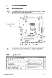
...USB connectors (10-1 pin USB56, USB78, USB910, USB1112) 10. Onboard LED (SB_PWR) 1-11 Page 1-13 1-9 1-10 1-14 1-13 1-1 ASUS P7H55-M LX/USB3 1-2 Place this side towards the rear of the chassis. System panel connector (10-1 pin F_PANEL) Page Connectors/Jumpers/Slots/LED 1-11 8. Digital audio...) EATXPWR 24.4cm(9.6in) VGA LGA1156 USB34 2 LAN1_USB12 CHA_FAN AUDIO ICS 9LRS954 Lithium Cell CMOS Power PCIEX16 RTL 8111E P7H55-M LX/USB3 SATA3G_1 Super I/O SB_PWR PCI1 PCI2 Intel® 64Mb BIOS 5 H55 SATA3G_2 SATA3G_5 SATA3G_3 PCIEX4_1 VIA VT1708S SPDIF_OUT COM USB1112...
...USB connectors (10-1 pin USB56, USB78, USB910, USB1112) 10. Onboard LED (SB_PWR) 1-11 Page 1-13 1-9 1-10 1-14 1-13 1-1 ASUS P7H55-M LX/USB3 1-2 Place this side towards the rear of the chassis. System panel connector (10-1 pin F_PANEL) Page Connectors/Jumpers/Slots/LED 1-11 8. Digital audio...) EATXPWR 24.4cm(9.6in) VGA LGA1156 USB34 2 LAN1_USB12 CHA_FAN AUDIO ICS 9LRS954 Lithium Cell CMOS Power PCIEX16 RTL 8111E P7H55-M LX/USB3 SATA3G_1 Super I/O SB_PWR PCI1 PCI2 Intel® 64Mb BIOS 5 H55 SATA3G_2 SATA3G_5 SATA3G_3 PCIEX4_1 VIA VT1708S SPDIF_OUT COM USB1112...

User Manual
Page 12
... with less power consumption. 1.3 Central Processing Unit (CPU) This motherboard comes with two Double Data Rate 3 (DDR3) Dual Inline Memory Module (DIMM) sockets. ASUS will process Return Merchandise Authorization (RMA) requests only if the motherboard comes with the cap on the LGA1156 socket. • The product warranty does not...DDR3 modules are not bent. Ensure that all power cables are unplugged before installing the CPU. • Upon purchase of the DDR3 DIMM sockets: P7H55-M LX/USB3 P7H55-M LX/USB3 240-pin DDR3 DIMM sockets DIMM_A1 DIMM_B1 1-3 Chapter 1: Product introduction
... with less power consumption. 1.3 Central Processing Unit (CPU) This motherboard comes with two Double Data Rate 3 (DDR3) Dual Inline Memory Module (DIMM) sockets. ASUS will process Return Merchandise Authorization (RMA) requests only if the motherboard comes with the cap on the LGA1156 socket. • The product warranty does not...DDR3 modules are not bent. Ensure that all power cables are unplugged before installing the CPU. • Upon purchase of the DDR3 DIMM sockets: P7H55-M LX/USB3 P7H55-M LX/USB3 240-pin DDR3 DIMM sockets DIMM_A1 DIMM_B1 1-3 Chapter 1: Product introduction

User Manual
Page 13
...modules from the higher-sized channel is recommended that you do either of 256 megabits (Mb) chips or less. P7H55-M LX/USB3 Series Motherboard Qualified Vendors List (QVL) DDR3-1333MHz capability Vendor Part No. A-Data Apacer CORSAIR CORSAIR Crucial Crucial ...•• 1.7V •• 1.65V • • 1.5V •• - •• - •• 1.5V •• ASUS P7H55-M LX/USB3 1-4 1.4.2 Memory configurations You may install 512MB, 1GB, 2GB, and 4GB unbuffered non-ECC DDR3 DIMMs into the DIMM sockets. • You may install varying memory...
...modules from the higher-sized channel is recommended that you do either of 256 megabits (Mb) chips or less. P7H55-M LX/USB3 Series Motherboard Qualified Vendors List (QVL) DDR3-1333MHz capability Vendor Part No. A-Data Apacer CORSAIR CORSAIR Crucial Crucial ...•• 1.7V •• 1.65V • • 1.5V •• - •• - •• 1.5V •• ASUS P7H55-M LX/USB3 1-4 1.4.2 Memory configurations You may install 512MB, 1GB, 2GB, and 4GB unbuffered non-ECC DDR3 DIMMs into the DIMM sockets. • You may install varying memory...

User Manual
Page 15
... on BIOS setup. 2. Failure to do not need to the chassis with the slot and press firmly until the card is already installed in a chassis). 3. ASUS P7H55-M LX/USB3 1-6 Replace the chassis cover. 1.5.2 Configuring an expansion card After installing the expansion card, configure it and make the necessary hardware settings for the card. 2. Secure...
... on BIOS setup. 2. Failure to do not need to the chassis with the slot and press firmly until the card is already installed in a chassis). 3. ASUS P7H55-M LX/USB3 1-6 Replace the chassis cover. 1.5.2 Configuring an expansion card After installing the expansion card, configure it and make the necessary hardware settings for the card. 2. Secure...

User Manual
Page 16
Move the jumper cap from pins 1-2 (default) to overclocking, use the CPU Parameter Recall (C.P.R.) feature. For system failure due to pins 2-3. P7H55-M LX/USB3 CLRTC 12 23 Normal (Default) Clear RTC P7H55-M LX/USB3 Clear RTC RAM To erase the RTC RAM: 1. Plug the power cord and turn ON the computer. 4. Keep the cap on CLRTC jumper...
Move the jumper cap from pins 1-2 (default) to overclocking, use the CPU Parameter Recall (C.P.R.) feature. For system failure due to pins 2-3. P7H55-M LX/USB3 CLRTC 12 23 Normal (Default) Clear RTC P7H55-M LX/USB3 Clear RTC RAM To erase the RTC RAM: 1. Plug the power cord and turn ON the computer. 4. Keep the cap on CLRTC jumper...
User Manual
Page 17
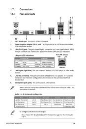
... Out To configure an 8-channel audio output: Use a chassis with HD audio module in the 2, 4, 6, or 8-channel configuration. Line Out port (lime). Microphone port (pink). ASUS P7H55-M LX/USB3 1-8 This port is for the LAN port LED indicators. Line In port (light blue). Video Graphics Adapter (VGA) port. 1.7 1.7.1 1 Connectors Rear panel ports 2 3 45 10...
... Out To configure an 8-channel audio output: Use a chassis with HD audio module in the 2, 4, 6, or 8-channel configuration. Line Out port (lime). Microphone port (pink). ASUS P7H55-M LX/USB3 1-8 This port is for the LAN port LED indicators. Line In port (light blue). Video Graphics Adapter (VGA) port. 1.7 1.7.1 1 Connectors Rear panel ports 2 3 45 10...

User Manual
Page 18
... NC USB+5V USB_P8USB_P8+ GND NC USB+5V USB_P6USB_P6+ GND NC USB1112 USB910 USB78 USB56 P7H55-M LX/USB3 PIN 1 PIN 1 PIN 1 PIN 1 USB+5V USB_P11USB_P11+ GND USB+5V USB_P9USB_P9+ GND USB+5V USB_P7USB_P7+ GND USB+5V USB_P5USB_P5+ GND P7H55-M LX/USB3 USB2.0 connectors Never connect a 1394 cable to USB 2.0/1.1 devices. 8. These two 4-pin Universal Serial Bus...
... NC USB+5V USB_P8USB_P8+ GND NC USB+5V USB_P6USB_P6+ GND NC USB1112 USB910 USB78 USB56 P7H55-M LX/USB3 PIN 1 PIN 1 PIN 1 PIN 1 USB+5V USB_P11USB_P11+ GND USB+5V USB_P9USB_P9+ GND USB+5V USB_P7USB_P7+ GND USB+5V USB_P5USB_P5+ GND P7H55-M LX/USB3 USB2.0 connectors Never connect a 1394 cable to USB 2.0/1.1 devices. 8. These two 4-pin Universal Serial Bus...

User Manual
Page 19
...Digital audio connector (4-1 pin SPDIF_OUT) This connector is for Serial ATA 3Gb/s hard disk and optical disk drives. ASUS P7H55-M LX/USB3 1-10 SATA3G_1 GND RSATA_TXP1 RSATA_TXN1 GND RSATA_RXP1 RSATA_RXN1 GND SATA3G_2 GND RSATA_RXN2 RSATA_RXP2 GND RSATA_TXN2 RSATA_TXP2 GND SATA3G_5 SATA3G_3 ... GND RSATA_RXP3 RSATA_RXN3 GND GND RSATA_RXN6 RSATA_RXP6 GND RSATA_TXN6 RSATA_TXP6 GND GND RSATA_RXN4 RSATA_RXP4 GND RSATA_TXN4 RSATA_TXP4 GND P7H55-M LX/USB3 SATA3G_6 SATA3G_4 P7H55-M LX/USB3 SATA connectors Install the Windows® XP Service Pack 2 or later version before using Serial ATA....
...Digital audio connector (4-1 pin SPDIF_OUT) This connector is for Serial ATA 3Gb/s hard disk and optical disk drives. ASUS P7H55-M LX/USB3 1-10 SATA3G_1 GND RSATA_TXP1 RSATA_TXN1 GND RSATA_RXP1 RSATA_RXN1 GND SATA3G_2 GND RSATA_RXN2 RSATA_RXP2 GND RSATA_TXN2 RSATA_TXP2 GND SATA3G_5 SATA3G_3 ... GND RSATA_RXP3 RSATA_RXN3 GND GND RSATA_RXN6 RSATA_RXP6 GND RSATA_TXN6 RSATA_TXP6 GND GND RSATA_RXN4 RSATA_RXP4 GND RSATA_TXN4 RSATA_TXP4 GND P7H55-M LX/USB3 SATA3G_6 SATA3G_4 P7H55-M LX/USB3 SATA connectors Install the Windows® XP Service Pack 2 or later version before using Serial ATA....
User Manual
Page 20
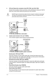
... to this connector. System panel connector (10-1 pin F_PANEL) This connector supports several chassis-mounted functions. Ground Reset P7H55-M LX/USB3 F_PANEL PIN 1 HD_LED RESET P7H55-M LX/USB3 System panel connector • System power LED (2-pin PLED) This 2-pin connector is for system reboot without turning...is read from or written to this connector. CPU_FAN CPU FAN PWM CPU FAN IN CPU FAN PWR GND P7H55-M LX/USB3 CHA_FAN GND +12V Rotation P7H55-M LX/USB3 fan connectors 5. They are not jumpers! Insufficient air flow inside the system may damage the motherboard components. Connect...
... to this connector. System panel connector (10-1 pin F_PANEL) This connector supports several chassis-mounted functions. Ground Reset P7H55-M LX/USB3 F_PANEL PIN 1 HD_LED RESET P7H55-M LX/USB3 System panel connector • System power LED (2-pin PLED) This 2-pin connector is for system reboot without turning...is read from or written to this connector. CPU_FAN CPU FAN PWM CPU FAN IN CPU FAN PWR GND P7H55-M LX/USB3 CHA_FAN GND +12V Rotation P7H55-M LX/USB3 fan connectors 5. They are not jumpers! Insufficient air flow inside the system may damage the motherboard components. Connect...
User Manual
Page 21
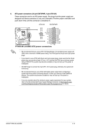
... 24-pin and 4-pin power plugs. • If you use a PSU with more power-consuming devices or when you are designed to install additional devices. ASUS P7H55-M LX/USB3 1-12 otherwise, the system will not boot up if the power is inadequate. • If you intend to fit these connectors in only one orientation...
... 24-pin and 4-pin power plugs. • If you use a PSU with more power-consuming devices or when you are designed to install additional devices. ASUS P7H55-M LX/USB3 1-12 otherwise, the system will not boot up if the power is inadequate. • If you intend to fit these connectors in only one orientation...

User Manual
Page 22
... a chassis-mounted front panel audio I /O module cable to hear system beeps and warnings. +5V GND GND Speaker Out SPEAKER P7H55-M LX/USB3 PIN 1 P7H55-M LX/USB3 Speaker Out Connector 1-13 Chapter 1: Product introduction GND PRESENCE# SENSE1_RETUR SENSE2_RETUR AGND NC NC NC AAFP PIN 1 PIN 1 MIC2... MICPWR Line out_R NC Line out_L PORT1 L PORT1 R PORT2 R SENSE_SEND PORT2 L P7H55-M LX/USB3 HD-audio-compliant Legacy AC'97 pin definition compliant definition P7H55-M LX/USB3 front panel audio connector If you want to connect a high-definition front panel audio module to this...
... a chassis-mounted front panel audio I /O module cable to hear system beeps and warnings. +5V GND GND Speaker Out SPEAKER P7H55-M LX/USB3 PIN 1 P7H55-M LX/USB3 Speaker Out Connector 1-13 Chapter 1: Product introduction GND PRESENCE# SENSE1_RETUR SENSE2_RETUR AGND NC NC NC AAFP PIN 1 PIN 1 MIC2... MICPWR Line out_R NC Line out_L PORT1 L PORT1 R PORT2 R SENSE_SEND PORT2 L P7H55-M LX/USB3 HD-audio-compliant Legacy AC'97 pin definition compliant definition P7H55-M LX/USB3 front panel audio connector If you want to connect a high-definition front panel audio module to this...

User Manual
Page 23
COM1 PIN 1 P7H55-M LX/USB3 P7H55-M LX/USB3 Serial port (COM1) connector ASUS P7H55-M LX/USB3 1-14 9. The serial port bracket (COM1) is for a serial (COM) port. Serial port connectors (10-1 pin COM1) The connector is purchased separately. Connect the serial port module cable to the connector, then install the module to a slot opening at the back of the system chassis.
COM1 PIN 1 P7H55-M LX/USB3 P7H55-M LX/USB3 Serial port (COM1) connector ASUS P7H55-M LX/USB3 1-14 9. The serial port bracket (COM1) is for a serial (COM) port. Serial port connectors (10-1 pin COM1) The connector is purchased separately. Connect the serial port module cable to the connector, then install the module to a slot opening at the back of the system chassis.

User Manual
Page 25
...then click Next. Click the Utilities tab, then click ASUS Update. 3. From the Windows® desktop, click Start > Programs > ASUS > ASUS Update > ASUS Update to complete the installation. b. Installing ASUS Update To install ASUS Update: 1. Chapter 2 BIOS information 2.1 Managing and ...ASUS FTP site nearest you want to restore the BIOS in the support DVD that comes with the motherboard package. Quit all Windows® applications before you update the BIOS using the ASUS Update utility. 2.1.1 ASUS Update The ASUS Update is available in the future. c. ASUS P7H55-M LX/USB3...
...then click Next. Click the Utilities tab, then click ASUS Update. 3. From the Windows® desktop, click Start > Programs > ASUS > ASUS Update > ASUS Update to complete the installation. b. Installing ASUS Update To install ASUS Update: 1. Chapter 2 BIOS information 2.1 Managing and ...ASUS FTP site nearest you want to restore the BIOS in the support DVD that comes with the motherboard package. Quit all Windows® applications before you update the BIOS using the ASUS Update utility. 2.1.1 ASUS Update The ASUS Update is available in the future. c. ASUS P7H55-M LX/USB3...

User Manual
Page 26
...an OS‑based utility. Updating from the Open window, then click Open. 3. ASUSTek EZ Flash 2 BIOS ROM Utility V4.14 Current ROM BOARD: P7H55 M LX USB3 VER: 0205 (H:00 B:00) DATE: 10/29/2010 Update ROM BOARD: Unknown VER: Unknown DATE: Unknown PATH: A:\ A: Note [Enter] Select... [B] Backup [V] Drive Info [ESC] Exit 2. Locate the BIOS file from a BIOS file a. Before you to complete the updating process. 2.1.2 ASUS EZ Flash 2 The ASUS EZ Flash 2 feature allows you start using EZ Flash 2: 1. When the correct BIOS file is found . b. Select Update BIOS from the...
...an OS‑based utility. Updating from the Open window, then click Open. 3. ASUSTek EZ Flash 2 BIOS ROM Utility V4.14 Current ROM BOARD: P7H55 M LX USB3 VER: 0205 (H:00 B:00) DATE: 10/29/2010 Update ROM BOARD: Unknown VER: Unknown DATE: Unknown PATH: A:\ A: Note [Enter] Select... [B] Backup [V] Drive Info [ESC] Exit 2. Locate the BIOS file from a BIOS file a. Before you to complete the updating process. 2.1.2 ASUS EZ Flash 2 The ASUS EZ Flash 2 feature allows you start using EZ Flash 2: 1. When the correct BIOS file is found . b. Select Update BIOS from the...

