
User Manual
Page 1
Motherboard P7H55-M LX/USB3
Motherboard P7H55-M LX/USB3

User Manual
Page 3
Contents Notices...v Safety information vi About this guide vi P7H55-M LX/USB3 specifications summary viii Chapter 1 Product introduction 1.1 Before you proceed 1-1 1.2 Motherboard overview 1-2 1.2.1 Motherboard layout 1-2 1.2.2 Layout contents 1-2 1.3 Central Processing Unit (CPU 1-3 1.4 System memory 1-3 1.4.1 Overview 1-3 1.4.2 Memory configurations 1-4 1.5 ... 1.8.2 Support DVD information 1-15 Chapter 2 BIOS information 2.1 Managing and updating your BIOS 2-1 2.1.1 ASUS Update 2-1 2.1.2 ASUS EZ Flash 2 2-2 2.1.3 ASUS BIOS Updater 2-3 2.1.4 ASUS CrashFree BIOS 3 2-6 iii
Contents Notices...v Safety information vi About this guide vi P7H55-M LX/USB3 specifications summary viii Chapter 1 Product introduction 1.1 Before you proceed 1-1 1.2 Motherboard overview 1-2 1.2.1 Motherboard layout 1-2 1.2.2 Layout contents 1-2 1.3 Central Processing Unit (CPU 1-3 1.4 System memory 1-3 1.4.1 Overview 1-3 1.4.2 Memory configurations 1-4 1.5 ... 1.8.2 Support DVD information 1-15 Chapter 2 BIOS information 2.1 Managing and updating your BIOS 2-1 2.1.1 ASUS Update 2-1 2.1.2 ASUS EZ Flash 2 2-2 2.1.3 ASUS BIOS Updater 2-3 2.1.4 ASUS CrashFree BIOS 3 2-6 iii

User Manual
Page 4
... 2.6 Boot menu 2-17 2.6.1 Boot Device Priority 2-17 2.6.2 Boot Settings Configuration 2-17 2.6.3 Security 2-18 2.7 Tools menu 2-19 2.7.1 AI NET 2 2-19 2.7.2 ASUS EZ Flash 2 2-19 2.7.3 IO Level up [Disabled 2-19 2.8 Exit menu 2-20 P7H55-M LX/USB3 motherboard installation notices 2-21 Intel® LGA1156 processor and chipset combination instruction... 2-21 Memory configuration 2-21 Configurations for the PCI Express...
... 2.6 Boot menu 2-17 2.6.1 Boot Device Priority 2-17 2.6.2 Boot Settings Configuration 2-17 2.6.3 Security 2-18 2.7 Tools menu 2-19 2.7.1 AI NET 2 2-19 2.7.2 ASUS EZ Flash 2 2-19 2.7.3 IO Level up [Disabled 2-19 2.8 Exit menu 2-20 P7H55-M LX/USB3 motherboard installation notices 2-21 Intel® LGA1156 processor and chipset combination instruction... 2-21 Memory configuration 2-21 Configurations for the PCI Express...

User Manual
Page 5
...technician for disposal of the crossed out wheeled bin indicates that may cause undesired operation. If this equipment. DO NOT throw the motherboard in municipal waste. This symbol of the crossed out wheeled bin indicates that to Part 15 of Communications Statement This digital apparatus ... This device complies with Part 15 of Chemicals) regulatory framework, we published the chemical substances in our products at ASUS REACH website at http://csr.asus.com/english/REACH.htm. This equipment has been tested and found to assure compliance with Canadian ICES-003. Check ...
...technician for disposal of the crossed out wheeled bin indicates that may cause undesired operation. If this equipment. DO NOT throw the motherboard in municipal waste. This symbol of the crossed out wheeled bin indicates that to Part 15 of Communications Statement This digital apparatus ... This device complies with Part 15 of Chemicals) regulatory framework, we published the chemical substances in our products at ASUS REACH website at http://csr.asus.com/english/REACH.htm. This equipment has been tested and found to assure compliance with Canadian ICES-003. Check ...
User Manual
Page 6
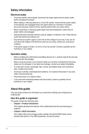
... away from connectors, slots, sockets and circuitry. • Avoid dust, humidity, and temperature extremes. Operation safety • Before installing the motherboard and adding devices on a stable surface. • If you detect any damage, contact your retailer. Detailed descriptions of the BIOS parameters are... all power cables from the existing system before you add a device. • Before connecting or removing signal cables from the motherboard, ensure that all power cables are also provided. If you encounter technical problems with the package. • Before using the product...
... away from connectors, slots, sockets and circuitry. • Avoid dust, humidity, and temperature extremes. Operation safety • Before installing the motherboard and adding devices on a stable surface. • If you detect any damage, contact your retailer. Detailed descriptions of the BIOS parameters are... all power cables from the existing system before you add a device. • Before connecting or removing signal cables from the motherboard, ensure that all power cables are also provided. If you encounter technical problems with the package. • Before using the product...

User Manual
Page 10
...it on it, check the items in the bag that came with a standby power LED that you install or remove any motherboard component. SB_PWR P7H55-M LX/USB3 ON OFF Standby Power Powered Off P7H55-M LX/USB3 Onboard LED 1-1 Chapter 1: Product introduction This is ON, in sleep mode, or in any component, switch off mode.... touching the ICs on them due to static electricity • Hold components by the edges to page ix for buying an ASUS® P7H55-M LX/USB3 motherboard! Failure to do so may cause severe damage to indicate that the system is a reminder that lights up to the...
...it on it, check the items in the bag that came with a standby power LED that you install or remove any motherboard component. SB_PWR P7H55-M LX/USB3 ON OFF Standby Power Powered Off P7H55-M LX/USB3 Onboard LED 1-1 Chapter 1: Product introduction This is ON, in sleep mode, or in any component, switch off mode.... touching the ICs on them due to static electricity • Hold components by the edges to page ix for buying an ASUS® P7H55-M LX/USB3 motherboard! Failure to do so may cause severe damage to indicate that the system is a reminder that lights up to the...
User Manual
Page 11
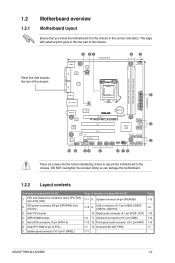
Doing so can damage the motherboard. 1.2.2 Layout contents Connectors/Jumpers/Slots/LED 1. Digital audio connector (4-1 pin SPDIF_OUT) 1-3 11. Clear RTC RAM (3-pin CLRTC) 7. Onboard LED (SB_PWR) 1-11 Page 1-13 1-9 1-10 1-14 1-13 1-1 ASUS P7H55-M LX/USB3 1-2 Place this side towards the rear of... 24.4cm(9.6in) VGA LGA1156 USB34 2 LAN1_USB12 CHA_FAN AUDIO ICS 9LRS954 Lithium Cell CMOS Power PCIEX16 RTL 8111E P7H55-M LX/USB3 SATA3G_1 Super I/O SB_PWR PCI1 PCI2 Intel® 64Mb BIOS 5 H55 SATA3G_2 SATA3G_5 SATA3G_3 PCIEX4_1 VIA VT1708S SPDIF_OUT ...
Doing so can damage the motherboard. 1.2.2 Layout contents Connectors/Jumpers/Slots/LED 1. Digital audio connector (4-1 pin SPDIF_OUT) 1-3 11. Clear RTC RAM (3-pin CLRTC) 7. Onboard LED (SB_PWR) 1-11 Page 1-13 1-9 1-10 1-14 1-13 1-1 ASUS P7H55-M LX/USB3 1-2 Place this side towards the rear of... 24.4cm(9.6in) VGA LGA1156 USB34 2 LAN1_USB12 CHA_FAN AUDIO ICS 9LRS954 Lithium Cell CMOS Power PCIEX16 RTL 8111E P7H55-M LX/USB3 SATA3G_1 Super I/O SB_PWR PCI1 PCI2 Intel® 64Mb BIOS 5 H55 SATA3G_2 SATA3G_5 SATA3G_3 PCIEX4_1 VIA VT1708S SPDIF_OUT ...

User Manual
Page 12
ASUS will shoulder the cost of the DDR3 DIMM sockets: P7H55-M LX/USB3 P7H55-M LX/USB3 240-pin DDR3 DIMM sockets DIMM_A1 DIMM_B1 1-3 Chapter 1: Product introduction The figure illustrates the location of repair only if the damage is missing, or if... damage to the socket contacts resulting from incorrect CPU installation/removal, or misplacement/loss/incorrect removal of the PnP cap. 1.4 System memory 1.4.1 Overview This motherboard comes with the cap on the socket and the socket contacts are developed for better performance with a surface mount LGA1156 socket designed for the Intel...
ASUS will shoulder the cost of the DDR3 DIMM sockets: P7H55-M LX/USB3 P7H55-M LX/USB3 240-pin DDR3 DIMM sockets DIMM_A1 DIMM_B1 1-3 Chapter 1: Product introduction The figure illustrates the location of repair only if the damage is missing, or if... damage to the socket contacts resulting from incorrect CPU installation/removal, or misplacement/loss/incorrect removal of the PnP cap. 1.4 System memory 1.4.1 Overview This motherboard comes with the cap on the socket and the socket contacts are developed for better performance with a surface mount LGA1156 socket designed for the Intel...

User Manual
Page 13
...- •• 1.7V •• 1.65V • • 1.5V •• - •• - •• 1.5V •• ASUS P7H55-M LX/USB3 1-4 DS DS APACER SS SS SS Micron DS SS ELPIDA AM5D5808DEWSBG 9FF22D9KPT J1108EDSE-DJ-F SS G.SKILL DS G.SKILL DS DS DS GEIL GL1L128M88BA12N DS SS...-DJ-F DS - - For optimum compatibility, it is then mapped for the OS can be about 3GB or less. P7H55-M LX/USB3 Series Motherboard Qualified Vendors List (QVL) DDR3-1333MHz capability Vendor Part No. The system maps the total size of the following: -...
...- •• 1.7V •• 1.65V • • 1.5V •• - •• - •• 1.5V •• ASUS P7H55-M LX/USB3 1-4 DS DS APACER SS SS SS Micron DS SS ELPIDA AM5D5808DEWSBG 9FF22D9KPT J1108EDSE-DJ-F SS G.SKILL DS G.SKILL DS DS DS GEIL GL1L128M88BA12N DS SS...-DJ-F DS - - For optimum compatibility, it is then mapped for the OS can be about 3GB or less. P7H55-M LX/USB3 Series Motherboard Qualified Vendors List (QVL) DDR3-1333MHz capability Vendor Part No. The system maps the total size of the following: -...

User Manual
Page 15
..., SCSI cards, USB cards, and other cards that comply with the PCI specifications. 1.5.4 PCI Express x4 slot This motherboard supports PCI Express x4 network cards, SCSI cards and other cards that comply with the PCI Express specifications. 1.5.5 PCI Express x16 ...the chassis cover. 1.5.2 Configuring an expansion card After installing the expansion card, configure it and make the necessary hardware settings for the card. 2. ASUS P7H55-M LX/USB3 1-6 Failure to the card. 3. Unplug the power cord before adding or removing expansion cards. Turn on BIOS setup. 2. Install the software drivers...
..., SCSI cards, USB cards, and other cards that comply with the PCI specifications. 1.5.4 PCI Express x4 slot This motherboard supports PCI Express x4 network cards, SCSI cards and other cards that comply with the PCI Express specifications. 1.5.5 PCI Express x16 ...the chassis cover. 1.5.2 Configuring an expansion card After installing the expansion card, configure it and make the necessary hardware settings for the card. 2. ASUS P7H55-M LX/USB3 1-6 Failure to the card. 3. Unplug the power cord before adding or removing expansion cards. Turn on BIOS setup. 2. Install the software drivers...

User Manual
Page 18
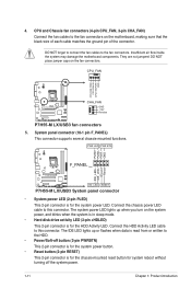
...motherboard! USB 2.0 ports 1 and 2. These two 4-pin Universal Serial Bus (USB) ports connect to the USB connectors. USB 3.0 ports 3 and 4. USB+5V USB_P12USB_P12+ GND NC USB+5V USB_P10USB_P10+ GND NC USB+5V USB_P8USB_P8+ GND NC USB+5V USB_P6USB_P6+ GND NC USB1112 USB910 USB78 USB56 P7H55-M LX/USB3... PIN 1 PIN 1 PIN 1 PIN 1 USB+5V USB_P11USB_P11+ GND USB+5V USB_P9USB_P9+ GND USB+5V USB_P7USB_P7+ GND USB+5V USB_P5USB_P5+ GND P7H55-M LX/USB3 USB2.0 connectors Never connect a 1394 cable to USB 2.0/1.1 ...
...motherboard! USB 2.0 ports 1 and 2. These two 4-pin Universal Serial Bus (USB) ports connect to the USB connectors. USB 3.0 ports 3 and 4. USB+5V USB_P12USB_P12+ GND NC USB+5V USB_P10USB_P10+ GND NC USB+5V USB_P8USB_P8+ GND NC USB+5V USB_P6USB_P6+ GND NC USB1112 USB910 USB78 USB56 P7H55-M LX/USB3... PIN 1 PIN 1 PIN 1 PIN 1 USB+5V USB_P11USB_P11+ GND USB+5V USB_P9USB_P9+ GND USB+5V USB_P7USB_P7+ GND USB+5V USB_P5USB_P5+ GND P7H55-M LX/USB3 USB2.0 connectors Never connect a 1394 cable to USB 2.0/1.1 ...
User Manual
Page 20
They are not jumpers! Insufficient air flow inside the system may damage the motherboard components. Connect the HDD Activity LED cable to the fan connectors. CPU and Chassis fan connectors (4-pin CPU_FAN, 3-pin CHA_FAN) Connect the...place jumper caps on the motherboard, making sure that the black wire of each cable matches the ground pin of the connector. CPU_FAN CPU FAN PWM CPU FAN IN CPU FAN PWR GND P7H55-M LX/USB3 CHA_FAN GND +12V Rotation P7H55-M LX/USB3 fan connectors 5. Ground Reset P7H55-M LX/USB3 F_PANEL PIN 1 HD_LED RESET P7H55-M LX/USB3 System panel connector •...
They are not jumpers! Insufficient air flow inside the system may damage the motherboard components. Connect the HDD Activity LED cable to the fan connectors. CPU and Chassis fan connectors (4-pin CPU_FAN, 3-pin CHA_FAN) Connect the...place jumper caps on the motherboard, making sure that the black wire of each cable matches the ground pin of the connector. CPU_FAN CPU FAN PWM CPU FAN IN CPU FAN PWR GND P7H55-M LX/USB3 CHA_FAN GND +12V Rotation P7H55-M LX/USB3 fan connectors 5. Ground Reset P7H55-M LX/USB3 F_PANEL PIN 1 HD_LED RESET P7H55-M LX/USB3 System panel connector •...

User Manual
Page 24
... and system stability. 1.8.2 Support DVD information The Support DVD that comes with the motherboard package contains drivers, software applications, and utilities that you can install to change at www.asus.com for updates. To run the DVD. 1-15 Chapter 1: Product introduction The ...locate the file ASSETUP.EXE from the BIN folder. Visit the ASUS website at any time without notice. Click an icon to display Support DVD/motherboard information Click an item to your hardware. • Motherboard settings and hardware options vary. 1.8 Software support 1.8.1 Installing an ...
... and system stability. 1.8.2 Support DVD information The Support DVD that comes with the motherboard package contains drivers, software applications, and utilities that you can install to change at www.asus.com for updates. To run the DVD. 1-15 Chapter 1: Product introduction The ...locate the file ASSETUP.EXE from the BIN folder. Visit the ASUS website at any time without notice. Click an icon to display Support DVD/motherboard information Click an item to your hardware. • Motherboard settings and hardware options vary. 1.8 Software support 1.8.1 Installing an ...

User Manual
Page 25
... the ASUS Update utility. 2.1.1 ASUS Update The ASUS Update is a utility that allows you to manage, save, and update the motherboard BIOS in the future. ASUS P7H55-M LX/USB3 2-1 Copy the original motherboard BIOS using this utility. Installing ASUS Update To install ASUS Update: 1. Click the Utilities tab, then click ASUS Update.... in the support DVD that you to restore the BIOS in Windows® environment. • ASUS Update requires an Internet connection either of the original motherboard BIOS file to a USB flash disk in case you need to avoid network traffic, or click...
... the ASUS Update utility. 2.1.1 ASUS Update The ASUS Update is a utility that allows you to manage, save, and update the motherboard BIOS in the future. ASUS P7H55-M LX/USB3 2-1 Copy the original motherboard BIOS using this utility. Installing ASUS Update To install ASUS Update: 1. Click the Utilities tab, then click ASUS Update.... in the support DVD that you to restore the BIOS in Windows® environment. • ASUS Update requires an Internet connection either of the original motherboard BIOS file to a USB flash disk in case you need to avoid network traffic, or click...
User Manual
Page 27
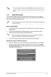
Prepare the motherboard support DVD and a USB flash drive in DOS environment 1. Download the latest BIOS file and BIOS Updater from the ASUS website at http:// support.asus.com and save the BIOS file and BIOS Updater to a hard disk drive or USB flash drive in DOS environment. Turn off ... utility also allows you to copy the current BIOS file that you to update BIOS in NTFS format. 3. When the ASUS Logo appears, press to boot using defaults ASUS P7H55-M LX/USB3 2-3 Do not save them on the USB flash drive. Insert the support DVD into the optical drive and select the optical...
Prepare the motherboard support DVD and a USB flash drive in DOS environment 1. Download the latest BIOS file and BIOS Updater from the ASUS website at http:// support.asus.com and save the BIOS file and BIOS Updater to a hard disk drive or USB flash drive in DOS environment. Turn off ... utility also allows you to copy the current BIOS file that you to update BIOS in NTFS format. 3. When the ASUS Logo appears, press to boot using defaults ASUS P7H55-M LX/USB3 2-3 Do not save them on the USB flash drive. Insert the support DVD into the optical drive and select the optical...

User Manual
Page 30
...Recovering the BIOS To recover the BIOS: 1. Turn on again. DO NOT shut down or reset the system while updating the BIOS! 2.1.4 ASUS CrashFree BIOS 3 ASUS CrashFree BIOS 3 is an auto recovery tool that allows you to ensure system compatibility and stability. When found, the utility reads the BIOS file...drive, if supported. 3. Insert the support DVD to the optical drive or the removable device that contains the BIOS file. • Before using the motherboard support DVD or a USB flash drive that contains the BIOS file to the USB port or to section 2.8 Exit menu for the BIOS file. ...
...Recovering the BIOS To recover the BIOS: 1. Turn on again. DO NOT shut down or reset the system while updating the BIOS! 2.1.4 ASUS CrashFree BIOS 3 ASUS CrashFree BIOS 3 is an auto recovery tool that allows you to ensure system compatibility and stability. When found, the utility reads the BIOS file...drive, if supported. 3. Insert the support DVD to the optical drive or the removable device that contains the BIOS file. • Before using the motherboard support DVD or a USB flash drive that contains the BIOS file to the USB port or to section 2.8 Exit menu for the BIOS file. ...

User Manual
Page 31
... reset button, or the ++ keys to force reset from the operating system. • The default BIOS settings for this motherboard apply for this motherboard. Entering BIOS Setup after POST To enter BIOS Setup after changing any BIOS settings, load the default settings to ensure system ... options.. If you do not press , POST continues with its parameters. Select the Load Setups Default item under the Exit Menu. ASUS P7H55-M LX/USB3 2-7 We recommend to always shut down the system properly from a running operating system can cause damage to ensure optimum performance. The...
... reset button, or the ++ keys to force reset from the operating system. • The default BIOS settings for this motherboard apply for this motherboard. Entering BIOS Setup after POST To enter BIOS Setup after changing any BIOS settings, load the default settings to ensure system ... options.. If you do not press , POST continues with its parameters. Select the Load Setups Default item under the Exit Menu. ASUS P7H55-M LX/USB3 2-7 We recommend to always shut down the system properly from a running operating system can cause damage to ensure optimum performance. The...

User Manual
Page 40
When set to the motherboard, the field shows N/A. When this item is not connected to [Last State], the system goes into off or on the +5VSB lead. This feature requires ... system. Configuration options: [Disabled] [Enabled] 2.5.6 Hardware Monitor CPU/MB Temperature [xxxºC/xxxºF] or [Ignored] The onboard hardware monitor automatically detects and displays the motherboard and CPU temperatures. 2.5.5 APM Configuration Restore on after an AC power loss. Configuration options: [Power Off] [Power On] [Last State] Power On By RTC Alarm...
When set to the motherboard, the field shows N/A. When this item is not connected to [Last State], the system goes into off or on the +5VSB lead. This feature requires ... system. Configuration options: [Disabled] [Enabled] 2.5.6 Hardware Monitor CPU/MB Temperature [xxxºC/xxxºF] or [Ignored] The onboard hardware monitor automatically detects and displays the motherboard and CPU temperatures. 2.5.5 APM Configuration Restore on after an AC power loss. Configuration options: [Power Off] [Power On] [Last State] Power On By RTC Alarm...
User Manual
Page 45
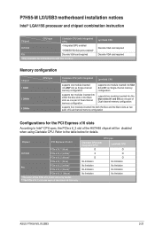
...P7H55-M LX/USB3 motherboard installation notices Intel® LGA1156 processor and chipset combination instruction Chipset CPU type Clarkdale CPU (with integrated GPU) H57/H55 • Integrated GPU enabled • HDMI/DVI/D-Sub ports enabled* P55 Discrete VGA card required * Only available for motherboards ... CPU O O X O O O No limitation No limitation No limitation No limitation No limitation No limitation No limitation No limitation ASUS P7H55-M LX/USB3 2-21 Refer to the table below for the PCI Express x16 slots According to Intel® CPU spec, the PCIe x 6_2...
...P7H55-M LX/USB3 motherboard installation notices Intel® LGA1156 processor and chipset combination instruction Chipset CPU type Clarkdale CPU (with integrated GPU) H57/H55 • Integrated GPU enabled • HDMI/DVI/D-Sub ports enabled* P55 Discrete VGA card required * Only available for motherboards ... CPU O O X O O O No limitation No limitation No limitation No limitation No limitation No limitation No limitation No limitation ASUS P7H55-M LX/USB3 2-21 Refer to the table below for the PCI Express x16 slots According to Intel® CPU spec, the PCIe x 6_2...

User Manual
Page 47
... harmful interference, and (2) this device must accept any interference received, including interference that the product Product Name : Motherboard Model Number : P7H55-M LX/USB3 Conforms to begin affixing CE marking:2010 Signature Country: TAIWAN Authorized representative in Europe: ASUS COMPUTER GmbH Address, City: HARKORT STR. 21-23, 40880 RATINGEN Country: GERMANY declare the following apparatus: Product...
... harmful interference, and (2) this device must accept any interference received, including interference that the product Product Name : Motherboard Model Number : P7H55-M LX/USB3 Conforms to begin affixing CE marking:2010 Signature Country: TAIWAN Authorized representative in Europe: ASUS COMPUTER GmbH Address, City: HARKORT STR. 21-23, 40880 RATINGEN Country: GERMANY declare the following apparatus: Product...


