
User Manual
Page 3
... this guide vi P7H55-M LX/USB3 specifications summary viii Chapter 1 Product introduction 1.1 Before you proceed 1-1 1.2 Motherboard overview 1-2 1.2.1 Motherboard layout 1-2 1.2.2 Layout contents 1-2 1.3 Central Processing Unit (CPU 1-3 1.4 System memory 1-3 1.4.1 Overview 1-3 1.4.2 Memory configurations 1-4 1.5 Expansion slots 1-6 1.5.1 Installing an expansion card 1-6 1.5.2 Configuring an expansion card 1-6 1.5.3 PCI slots 1-6 1.5.4 PCI Express x4 slot 1-6 1.5.5 PCI Express x16 slot 1-6 1.6 Jumpers 1-7 1.7 Connectors 1-8 1.7.1 Rear panel...
... this guide vi P7H55-M LX/USB3 specifications summary viii Chapter 1 Product introduction 1.1 Before you proceed 1-1 1.2 Motherboard overview 1-2 1.2.1 Motherboard layout 1-2 1.2.2 Layout contents 1-2 1.3 Central Processing Unit (CPU 1-3 1.4 System memory 1-3 1.4.1 Overview 1-3 1.4.2 Memory configurations 1-4 1.5 Expansion slots 1-6 1.5.1 Installing an expansion card 1-6 1.5.2 Configuring an expansion card 1-6 1.5.3 PCI slots 1-6 1.5.4 PCI Express x4 slot 1-6 1.5.5 PCI Express x16 slot 1-6 1.6 Jumpers 1-7 1.7 Connectors 1-8 1.7.1 Rear panel...
User Manual
Page 6
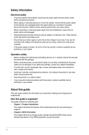
... came with the product, contact a qualified service technician or your dealer immediately. • To avoid short circuits, keep paper clips, screws, and staples away from connectors, slots, sockets and circuitry. • Avoid dust, humidity, and temperature extremes. vi Contact a qualified service technician or your area. If you add a device. • Before...
... came with the product, contact a qualified service technician or your dealer immediately. • To avoid short circuits, keep paper clips, screws, and staples away from connectors, slots, sockets and circuitry. • Avoid dust, humidity, and temperature extremes. vi Contact a qualified service technician or your area. If you add a device. • Before...

User Manual
Page 8
...1333/1066 MHz, non-ECC, un- buffered memory * Refer to www.asus.com for Intel® CPU support list. ASUS MyLogo 2 - resolution: 2048 x 1536 @75Hz Intel® H55 Express Chipset: - 6 x Serial ATA 3.0 Gb/s connectors Realtek® 8111E Gigabit LAN PCIe controller VIA® VT1708S 8-channel* ...; 32-bit operating system may only recognize less than 3GB. ASUS AI NET 2 - ASUS CrashFree BIOS 3 - Multi-language BIOS (continued on the next page) viii DVI-D with Max. ASUS EZ Flash 2 - P7H55-M LX/USB3 specifications summary CPU Chipset Memory Expansion slots VGA output Storage LAN Audio...
...1333/1066 MHz, non-ECC, un- buffered memory * Refer to www.asus.com for Intel® CPU support list. ASUS MyLogo 2 - resolution: 2048 x 1536 @75Hz Intel® H55 Express Chipset: - 6 x Serial ATA 3.0 Gb/s connectors Realtek® 8111E Gigabit LAN PCIe controller VIA® VT1708S 8-channel* ...; 32-bit operating system may only recognize less than 3GB. ASUS AI NET 2 - ASUS CrashFree BIOS 3 - Multi-language BIOS (continued on the next page) viii DVI-D with Max. ASUS EZ Flash 2 - P7H55-M LX/USB3 specifications summary CPU Chipset Memory Expansion slots VGA output Storage LAN Audio...

User Manual
Page 9
P7H55-M LX/ USB3 specifications summary Rear panel ports Internal connectors BIOS features Manageability Accessories Support DVD Form factor 1 x PS/2 Mouse port 1 x PS/2 Keyboard port 1 x D-Sub port 1 x DVI-D port 1 x LAN (RJ-45) port 2 x USB 2.0/1.1 ports 2 x USB 3.0/2.0 ports (blue) 3 x Audio jacks 4 x USB 2.0/1.1 connectors support additional 8 USB 2.0/1.1 ports 6 x SATA connectors 1 x 24-pin EATX power connector 1 x 4-pin ATX 12V power connector 1 x CPU fan...
P7H55-M LX/ USB3 specifications summary Rear panel ports Internal connectors BIOS features Manageability Accessories Support DVD Form factor 1 x PS/2 Mouse port 1 x PS/2 Keyboard port 1 x D-Sub port 1 x DVI-D port 1 x LAN (RJ-45) port 2 x USB 2.0/1.1 ports 2 x USB 3.0/2.0 ports (blue) 3 x Audio jacks 4 x USB 2.0/1.1 connectors support additional 8 USB 2.0/1.1 ports 6 x SATA connectors 1 x 24-pin EATX power connector 1 x 4-pin ATX 12V power connector 1 x CPU fan...
User Manual
Page 11
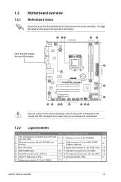
... into the chassis in the correct orientation. DO NOT overtighten the screws! ATX power connectors (24-pin EATXPWR, 4-pin ATX12V) 3. Clear RTC RAM (3-pin CLRTC) 7. USB connectors (10-1 pin USB56, USB78, USB910, USB1112) 10. Onboard LED (SB_PWR) 1-11 Page 1-13 1-9 1-10 1-14 1-13 1-1 ASUS P7H55-M LX/USB3 1-2 The edge with external ports goes to the chassis.
... into the chassis in the correct orientation. DO NOT overtighten the screws! ATX power connectors (24-pin EATXPWR, 4-pin ATX12V) 3. Clear RTC RAM (3-pin CLRTC) 7. USB connectors (10-1 pin USB56, USB78, USB910, USB1112) 10. Onboard LED (SB_PWR) 1-11 Page 1-13 1-9 1-10 1-14 1-13 1-1 ASUS P7H55-M LX/USB3 1-2 The edge with external ports goes to the chassis.

User Manual
Page 15
Align the card connector with the slot and press firmly until the card is already installed in a chassis). 3. Replace the chassis cover. 1.5.2 Configuring an expansion card After installing the expansion card, configure it and make the necessary hardware settings for the card. 2. ASUS P7H55-M LX/USB3 1-6 Failure to do not need to use. 4. Turn on BIOS...
Align the card connector with the slot and press firmly until the card is already installed in a chassis). 3. Replace the chassis cover. 1.5.2 Configuring an expansion card After installing the expansion card, configure it and make the necessary hardware settings for the card. 2. ASUS P7H55-M LX/USB3 1-6 Failure to do not need to use. 4. Turn on BIOS...
User Manual
Page 17
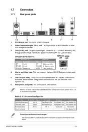
... to support an 8-channel audio output. This port allows Gigabit connection to a headphone or a speaker. Microphone port (pink). ASUS P7H55-M LX/USB3 1-8 Refer to the table below for the function of this port becomes Front Speaker Out. 6. LAN port LED indications ACT/...This port is for a PS/2 mouse. 2. This port connects to a Local Area Network (LAN) through a network hub. This port connects a microphone. 1.7 1.7.1 1 Connectors Rear panel ports 2 3 45 10 9 8 7 6 1. LAN (RJ-45) port. Audio 2, 4, 6, 8-channel configuration Port Light Blue (Rear panel) Lime ...
... to support an 8-channel audio output. This port allows Gigabit connection to a headphone or a speaker. Microphone port (pink). ASUS P7H55-M LX/USB3 1-8 Refer to the table below for the function of this port becomes Front Speaker Out. 6. LAN port LED indications ACT/...This port is for a PS/2 mouse. 2. This port connects to a Local Area Network (LAN) through a network hub. This port connects a microphone. 1.7 1.7.1 1 Connectors Rear panel ports 2 3 45 10 9 8 7 6 1. LAN (RJ-45) port. Audio 2, 4, 6, 8-channel configuration Port Light Blue (Rear panel) Lime ...

User Manual
Page 18
... to output RGB Signal to USB 3.0 ports for faster and better performance for your USB 3.0 devices. 9. USB connectors (10-1 pin USB56, USB78, USB910, USB1112) These connectors are for any USB 3.0 port when installing Windows® operating system. • Due to USB 3.0 controller limitation...GND NC USB+5V USB_P6USB_P6+ GND NC USB1112 USB910 USB78 USB56 P7H55-M LX/USB3 PIN 1 PIN 1 PIN 1 PIN 1 USB+5V USB_P11USB_P11+ GND USB+5V USB_P9USB_P9+ GND USB+5V USB_P7USB_P7+ GND USB+5V USB_P5USB_P5+ GND P7H55-M LX/USB3 USB2.0 connectors Never connect a 1394 cable to USB 2.0/1.1 devices. 8. ...
... to output RGB Signal to USB 3.0 ports for faster and better performance for your USB 3.0 devices. 9. USB connectors (10-1 pin USB56, USB78, USB910, USB1112) These connectors are for any USB 3.0 port when installing Windows® operating system. • Due to USB 3.0 controller limitation...GND NC USB+5V USB_P6USB_P6+ GND NC USB1112 USB910 USB78 USB56 P7H55-M LX/USB3 PIN 1 PIN 1 PIN 1 PIN 1 USB+5V USB_P11USB_P11+ GND USB+5V USB_P9USB_P9+ GND USB+5V USB_P7USB_P7+ GND USB+5V USB_P5USB_P5+ GND P7H55-M LX/USB3 USB2.0 connectors Never connect a 1394 cable to USB 2.0/1.1 devices. 8. ...

User Manual
Page 19
... ATA signal cables for an additional Sony/Philips Digital Interface (S/PDIF) port. +5V SPDIFOUT GND P7H55-M LX/USB3 SPDIF_OUT P7H55-M LX/USB3 Digital audio connector The S/PDIF module is backward compatible with 133MB/s (Ultra DMA133). SATA3G_1 GND RSATA_TXP1 RSATA_TXN1 GND RSATA_RXP1... RSATA_RXN6 RSATA_RXP6 GND RSATA_TXN6 RSATA_TXP6 GND GND RSATA_RXN4 RSATA_RXP4 GND RSATA_TXN4 RSATA_TXP4 GND P7H55-M LX/USB3 SATA3G_6 SATA3G_4 P7H55-M LX/USB3 SATA connectors Install the Windows® XP Service Pack 2 or later version before using Serial ATA. 3. ASUS P7H55-M LX/USB3 1-10 2.
... ATA signal cables for an additional Sony/Philips Digital Interface (S/PDIF) port. +5V SPDIFOUT GND P7H55-M LX/USB3 SPDIF_OUT P7H55-M LX/USB3 Digital audio connector The S/PDIF module is backward compatible with 133MB/s (Ultra DMA133). SATA3G_1 GND RSATA_TXP1 RSATA_TXN1 GND RSATA_RXP1... RSATA_RXN6 RSATA_RXP6 GND RSATA_TXN6 RSATA_TXP6 GND GND RSATA_RXN4 RSATA_RXP4 GND RSATA_TXN4 RSATA_TXP4 GND P7H55-M LX/USB3 SATA3G_6 SATA3G_4 P7H55-M LX/USB3 SATA connectors Install the Windows® XP Service Pack 2 or later version before using Serial ATA. 3. ASUS P7H55-M LX/USB3 1-10 2.
User Manual
Page 20
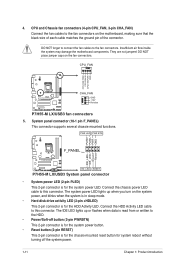
... GND IDE_LED+ IDE_LED- CPU_FAN CPU FAN PWM CPU FAN IN CPU FAN PWR GND P7H55-M LX/USB3 CHA_FAN GND +12V Rotation P7H55-M LX/USB3 fan connectors 5. Ground Reset P7H55-M LX/USB3 F_PANEL PIN 1 HD_LED RESET P7H55-M LX/USB3 System panel connector • System power LED (2-pin PLED) This 2-pin connector is for the chassis-mounted reset button for system reboot without turning off the system...
... GND IDE_LED+ IDE_LED- CPU_FAN CPU FAN PWM CPU FAN IN CPU FAN PWR GND P7H55-M LX/USB3 CHA_FAN GND +12V Rotation P7H55-M LX/USB3 fan connectors 5. Ground Reset P7H55-M LX/USB3 F_PANEL PIN 1 HD_LED RESET P7H55-M LX/USB3 System panel connector • System power LED (2-pin PLED) This 2-pin connector is for the chassis-mounted reset button for system reboot without turning off the system...
User Manual
Page 21
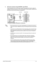
... an ATX power supply. Find the proper orientation and push down firmly until the connectors completely fit. ATX power connectors (24-pin EATXPWR, 4-pin ATX12V) These connectors are for details. ATX12V EATXPWR +12V DC +12V DC P7H55-M LX/USB3 GND GND +3 Volts +12 Volts +12 Volts +5V Standby Power OK PIN... least 15 A on +12 V and that the 20-pin power plug can provide at http://support.asus. The plugs from the power supply are uncertain about the minimum power supply requirement for your system, refer to connect the 4-pin ATX +12 V power plug; ASUS P7H55-M LX/USB3 1-12
... an ATX power supply. Find the proper orientation and push down firmly until the connectors completely fit. ATX power connectors (24-pin EATXPWR, 4-pin ATX12V) These connectors are for details. ATX12V EATXPWR +12V DC +12V DC P7H55-M LX/USB3 GND GND +3 Volts +12 Volts +12 Volts +5V Standby Power OK PIN... least 15 A on +12 V and that the 20-pin power plug can provide at http://support.asus. The plugs from the power supply are uncertain about the minimum power supply requirement for your system, refer to connect the 4-pin ATX +12 V power plug; ASUS P7H55-M LX/USB3 1-12

User Manual
Page 22
... 1 MIC2 MICPWR Line out_R NC Line out_L PORT1 L PORT1 R PORT2 R SENSE_SEND PORT2 L P7H55-M LX/USB3 HD-audio-compliant Legacy AC'97 pin definition compliant definition P7H55-M LX/USB3 front panel audio connector If you want to connect an AC97 front panel audio module to this connector, set to [HD Audio]. See section 2.4.3 Onboard Devices Configuration for the chassis...
... 1 MIC2 MICPWR Line out_R NC Line out_L PORT1 L PORT1 R PORT2 R SENSE_SEND PORT2 L P7H55-M LX/USB3 HD-audio-compliant Legacy AC'97 pin definition compliant definition P7H55-M LX/USB3 front panel audio connector If you want to connect an AC97 front panel audio module to this connector, set to [HD Audio]. See section 2.4.3 Onboard Devices Configuration for the chassis...

User Manual
Page 23
Serial port connectors (10-1 pin COM1) The connector is purchased separately. The serial port bracket (COM1) is for a serial (COM) port. COM1 PIN 1 P7H55-M LX/USB3 P7H55-M LX/USB3 Serial port (COM1) connector ASUS P7H55-M LX/USB3 1-14 Connect the serial port module cable to the connector, then install the module to a slot opening at the back of the system chassis. 9.
Serial port connectors (10-1 pin COM1) The connector is purchased separately. The serial port bracket (COM1) is for a serial (COM) port. COM1 PIN 1 P7H55-M LX/USB3 P7H55-M LX/USB3 Serial port (COM1) connector ASUS P7H55-M LX/USB3 1-14 Connect the serial port module cable to the connector, then install the module to a slot opening at the back of the system chassis. 9.

User Manual
Page 33
When set or change the configurations for the Serial ATA connectors supported by Windows Vista/7 with LBA mode disabled. Configuration options: [Disabled] [Enabled] 2.3.5 Storage Configuration The items in the system. Select... to set to [Disabled], the data transfer from and to the device occurs one sector at a time if the device supports multi-sector transfer feature. ASUS P7H55-M LX/USB3 2-9 Configuration options: [Auto] SMART Monitoring [Auto] Sets the Smart Monitoring, Analysis, and Reporting Technology. Configuration options: [Disabled] [Compatible] [Enhanced] Configure SATA...
When set or change the configurations for the Serial ATA connectors supported by Windows Vista/7 with LBA mode disabled. Configuration options: [Disabled] [Enabled] 2.3.5 Storage Configuration The items in the system. Select... to set to [Disabled], the data transfer from and to the device occurs one sector at a time if the device supports multi-sector transfer feature. ASUS P7H55-M LX/USB3 2-9 Configuration options: [Auto] SMART Monitoring [Auto] Sets the Smart Monitoring, Analysis, and Reporting Technology. Configuration options: [Disabled] [Compatible] [Enhanced] Configure SATA...


