User Manual
Page 17
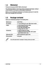
... (4-pin) module Cables 1 x 2-port Serial ATA power cables 6 x Serial ATA signal cables 1 x Ultra DMA 133/100/66 cable 1 x Floppy disk drive cable Accessories 1 x ASUS Q-Shield (I/O shield) 1 x ASUS Q-Connector Kit (USB, 1394, system panel; The motherboard delivers a host of new features and latest technologies, making it , check the items in the long line of the above items is damaged or missing, contact your motherboard package for buying an ASUS® P5QC motherboard! ASUS P5QC 1-1 Retail version only) Application DVD ASUS motherboard support DVD Documentation User guide...
... (4-pin) module Cables 1 x 2-port Serial ATA power cables 6 x Serial ATA signal cables 1 x Ultra DMA 133/100/66 cable 1 x Floppy disk drive cable Accessories 1 x ASUS Q-Shield (I/O shield) 1 x ASUS Q-Connector Kit (USB, 1394, system panel; The motherboard delivers a host of new features and latest technologies, making it , check the items in the long line of the above items is damaged or missing, contact your motherboard package for buying an ASUS® P5QC motherboard! ASUS P5QC 1-1 Retail version only) Application DVD ASUS motherboard support DVD Documentation User guide...
User Manual
Page 39
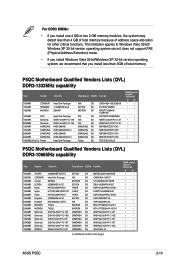
...; • • • P5QC Motherboard Qualified Vendors Lists (QVL) DDR3-1066MHz capability Size Vendor Chip No. This limitation applies to Windows Vista 32-bit/ Windows XP 32-bit version operating system since it does not support PAE (Physical Address Extention) mode. • If you install Windows Vista 32-bit/Windows XP 32-bit version operating system, we recommend that you install one 4 GB or two 2 GB memory modules, the system...
...; • • • P5QC Motherboard Qualified Vendors Lists (QVL) DDR3-1066MHz capability Size Vendor Chip No. This limitation applies to Windows Vista 32-bit/ Windows XP 32-bit version operating system since it does not support PAE (Physical Address Extention) mode. • If you install Windows Vista 32-bit/Windows XP 32-bit version operating system, we recommend that you install one 4 GB or two 2 GB memory modules, the system...
User Manual
Page 44
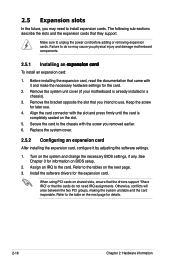
... expansion card. When using PCI cards on BIOS setup. 2. Secure the card to do not need to unplug the power cord before adding or removing expansion cards. Install the software drivers for information on shared slots, ensure that the drivers support "Share IRQ" or that came with the slot and press firmly until the card is already installed in a chassis). 3. Turn on the slot. 5. Refer to use . 4. Remove the bracket opposite the slot that they support...
... expansion card. When using PCI cards on BIOS setup. 2. Secure the card to do not need to unplug the power cord before adding or removing expansion cards. Install the software drivers for information on shared slots, ensure that the drivers support "Share IRQ" or that came with the slot and press firmly until the card is already installed in a chassis). 3. Turn on the slot. 5. Refer to use . 4. Remove the bracket opposite the slot that they support...

User Manual
Page 49
ASUS P5QC 2-23 Pins 2-3 (Default) Pins 1-2 (OV Enabled) OV_CPU up to 1.70V up to 2.10V OV_NB up to 1.76V up to 2.20V • Before you change the jumper settings for example, a water-cooling system) to halt. 4. Doing so may need a better cooling system (for extra-high overvoltage ability, use the BIOS items introduced in BIOS. For system failure due to the wrong setting of these two...
ASUS P5QC 2-23 Pins 2-3 (Default) Pins 1-2 (OV Enabled) OV_CPU up to 1.70V up to 2.10V OV_NB up to 1.76V up to 2.20V • Before you change the jumper settings for example, a water-cooling system) to halt. 4. Doing so may need a better cooling system (for extra-high overvoltage ability, use the BIOS items introduced in BIOS. For system failure due to the wrong setting of these two...
User Manual
Page 69
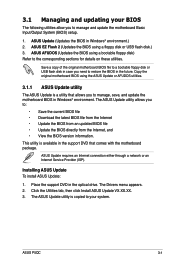
... of the original motherboard BIOS file to a bootable floppy disk or USB flash disk in the support DVD that allows you to the corresponding sections for details on these utilities. Installing ASUS Update To install ASUS Update: 1. Place the support DVD in Windows® environment.) 2. Click the Utilities tab, then click Install ASUS Update VX.XX.XX. 3. ASUS P5QC 3-1 Copy the original motherboard BIOS using a bootable floppy disk) Refer to manage and update the motherboard Basic Input/Output System (BIOS) setup. 1. This utility is available in...
... of the original motherboard BIOS file to a bootable floppy disk or USB flash disk in the support DVD that allows you to the corresponding sections for details on these utilities. Installing ASUS Update To install ASUS Update: 1. Place the support DVD in Windows® environment.) 2. Click the Utilities tab, then click Install ASUS Update VX.XX.XX. 3. ASUS P5QC 3-1 Copy the original motherboard BIOS using a bootable floppy disk) Refer to manage and update the motherboard Basic Input/Output System (BIOS) setup. 1. This utility is available in...

User Manual
Page 79
... device is installed in the system. Configuration options: [Disabled] [Auto] Block (Multi-Sector Transfer) M [Auto] Enables or disables data multi-sectors transfers. Configuration options: [Disabled] [Auto] PIO Mode [Auto] Allows you are not user-configurable. Main BIOS SETUP UTILITY SATA 1 Device : Hard Disk Vendor : WDC WD800JD-00LSA0 Size 80.0GB LBA Mode : Supported Block Mode : 16Sectors PIO Mode : 4 Async DMA : MultiWord DMA-2 Ultra DMA : Ultra DMA-5 SMART Monitoring: Supported Select the type of the appropriate IDE device type. Change...
... device is installed in the system. Configuration options: [Disabled] [Auto] Block (Multi-Sector Transfer) M [Auto] Enables or disables data multi-sectors transfers. Configuration options: [Disabled] [Auto] PIO Mode [Auto] Allows you are not user-configurable. Main BIOS SETUP UTILITY SATA 1 Device : Hard Disk Vendor : WDC WD800JD-00LSA0 Size 80.0GB LBA Mode : Supported Block Mode : 16Sectors PIO Mode : 4 Async DMA : MultiWord DMA-2 Ultra DMA : Ultra DMA-5 SMART Monitoring: Supported Select the type of the appropriate IDE device type. Change...

User Manual
Page 80
...[Compatible] [Enhanced] Configure SATA as Parallel ATA physical storage devices, keep the default setting [IDE]. • If you want to create a RAID 0, RAID 1, RAID 5, RAID 10, or the Intel® Matrix Storage Technology configuration from the Serial ATA hard disk drives, set or change the configurations for the SATA devices installed in this item to [RAID]. 3-12 Chapter 3: BIOS setup DMA Mode [Auto] Selects the DMA mode. Configuration options: [IDE] [RAID] [AHCI] • If you want to use the Serial ATA hard disk drives as [IDE] Sets the configuration for the Serial ATA connectors...
...[Compatible] [Enhanced] Configure SATA as Parallel ATA physical storage devices, keep the default setting [IDE]. • If you want to create a RAID 0, RAID 1, RAID 5, RAID 10, or the Intel® Matrix Storage Technology configuration from the Serial ATA hard disk drives, set or change the configurations for the SATA devices installed in this item to [RAID]. 3-12 Chapter 3: BIOS setup DMA Mode [Auto] Selects the DMA mode. Configuration options: [IDE] [RAID] [AHCI] • If you want to use the Serial ATA hard disk drives as [IDE] Sets the configuration for the Serial ATA connectors...

User Manual
Page 83
...[Auto] Ai Clock Twister [Auto] Ai Transaction Booster [Auto] Options Manual Auto Select Screen Select Item Enter Go to individually set overclocking parameters. Loads the optimal settings for the system. Select either one of the preset overclocking configuration options: Manual Auto Allows you to configure overclocking-related items. Take caution when changing the settings of CPU overclocking options to malfunction. Scroll down to display the following items vary depending on the CPU and BIOS SETUP UTILITY Main Ai Tweaker Advanced Power Boot Tools...
...[Auto] Ai Clock Twister [Auto] Ai Transaction Booster [Auto] Options Manual Auto Select Screen Select Item Enter Go to individually set overclocking parameters. Loads the optimal settings for the system. Select either one of the preset overclocking configuration options: Manual Auto Allows you to configure overclocking-related items. Take caution when changing the settings of CPU overclocking options to malfunction. Scroll down to display the following items vary depending on the CPU and BIOS SETUP UTILITY Main Ai Tweaker Advanced Power Boot Tools...

User Manual
Page 90
... invalid ratio is set in this screen may differ. BIOS SETUP UTILITY Main Ai Tweaker Advanced Power Boot Tools Exit CPU Configuration Chipset Onboard Devices Configuration USB Configuration PCIPnP Configure CPU. Select Screen Select Item Enter Go to adjust the ratio between CPU Core Clock and the FSB Frequency. Use the and keys to change the settings for the CPU and other system devices. 3.5 Advanced menu The Advanced menu items allow you to adjust the value. BIOS SETUP UTILITY Advanced Configure advanced CPU settings Manufacturer:Intel Brand...
... invalid ratio is set in this screen may differ. BIOS SETUP UTILITY Main Ai Tweaker Advanced Power Boot Tools Exit CPU Configuration Chipset Onboard Devices Configuration USB Configuration PCIPnP Configure CPU. Select Screen Select Item Enter Go to adjust the ratio between CPU Core Clock and the FSB Frequency. Use the and keys to change the settings for the CPU and other system devices. 3.5 Advanced menu The Advanced menu items allow you to adjust the value. BIOS SETUP UTILITY Advanced Configure advanced CPU settings Manufacturer:Intel Brand...
User Manual
Page 93
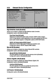
...options: [SPDIF Output] [HDMI Output] Marvell IDE [Enabled] Allows you to set the video output mode of your graphics card. Configuration options: [Disabled] [Enabled] LSI Firewire 1394 [Enabled] Configuration options: [Enabled] [Disabled] ASUS P5QC 3-25 Configuration options: [Enabled] [Disabled] LAN Boot ROM [Disabled] This item appears only when you set the front panel audio connector (AAFP) mode to enable or disable the onboard Atheros Gigabit LAN. Configuration options: [AC97] [HD Audio] SPDIF_OUT Mode Setting [SPDIF Output] Allows you to legacy AC'97 or high-definition audio...
...options: [SPDIF Output] [HDMI Output] Marvell IDE [Enabled] Allows you to set the video output mode of your graphics card. Configuration options: [Disabled] [Enabled] LSI Firewire 1394 [Enabled] Configuration options: [Enabled] [Disabled] ASUS P5QC 3-25 Configuration options: [Enabled] [Disabled] LAN Boot ROM [Disabled] This item appears only when you set the front panel audio connector (AAFP) mode to enable or disable the onboard Atheros Gigabit LAN. Configuration options: [AC97] [HD Audio] SPDIF_OUT Mode Setting [SPDIF Output] Allows you to legacy AC'97 or high-definition audio...

User Manual
Page 96
BIOS SETUP UTILITY Main Ai Tweaker Advanced Power Boot Tools Exit Suspend Mode Repost Video on S3 Resume ACPI 2.0 Support ACPI APIC Support [Auto] [No] [Disabled] [Enabled] Select the ACPI state used for system suspend. Configuration options: [Disabled] [Enabled] 3-28 Chapter 3: BIOS setup Configuration options: [S1 (POS) Only] [S3 Only] [Auto] 3.6.2 Repost Video on S3/STR resume. Configuration options: [Disabled] [Enabled] 3.6.4 ACPI APIC Support [Enabled] Allows you to invoke VGA BIOS POST on S3 Resume [No] Determines whether to enable or disable ...
BIOS SETUP UTILITY Main Ai Tweaker Advanced Power Boot Tools Exit Suspend Mode Repost Video on S3 Resume ACPI 2.0 Support ACPI APIC Support [Auto] [No] [Disabled] [Enabled] Select the ACPI state used for system suspend. Configuration options: [Disabled] [Enabled] 3-28 Chapter 3: BIOS setup Configuration options: [S1 (POS) Only] [S3 Only] [Auto] 3.6.2 Repost Video on S3/STR resume. Configuration options: [Disabled] [Enabled] 3.6.4 ACPI APIC Support [Enabled] Allows you to invoke VGA BIOS POST on S3 Resume [No] Determines whether to enable or disable ...

User Manual
Page 98
... the motherboard, the field shows [N/A]. Configuration options: [Disabled] [Space Bar] [Ctrl-Esc] [Power Key] 3.6.6 Hardware Monitor BIOS SETUP UTILITY Power Hardware Monitor CPU Temperature MB Temperature [47ºC/116.5ºF] [32ºC/89.5ºF] CPU Temperature CPU Fan Speed CPU Q-Fan Control [4500RPM] [Disabled] Chassis Fan 1 Speed Chassis Fan 2 Speed Chassis Q-Fan Control [N/A] [N/A] [Disabled] Power Fan Speed [N/A] CPU Voltage 3.3V Voltage 5V Voltage 12V Voltage [ 1.304V] [ 3.248V] [ 5.112V] [12.096V] Select Screen Select Item +- Change Field...
... the motherboard, the field shows [N/A]. Configuration options: [Disabled] [Space Bar] [Ctrl-Esc] [Power Key] 3.6.6 Hardware Monitor BIOS SETUP UTILITY Power Hardware Monitor CPU Temperature MB Temperature [47ºC/116.5ºF] [32ºC/89.5ºF] CPU Temperature CPU Fan Speed CPU Q-Fan Control [4500RPM] [Disabled] Chassis Fan 1 Speed Chassis Fan 2 Speed Chassis Q-Fan Control [N/A] [N/A] [Disabled] Power Fan Speed [N/A] CPU Voltage 3.3V Voltage 5V Voltage 12V Voltage [ 1.304V] [ 3.248V] [ 5.112V] [12.096V] Select Screen Select Item +- Change Field...

User Manual
Page 100
...-ROM drive as the first boot device. Select Screen Select Item Enter Go to change the system boot options. Select an item then press to display the sub-menu. A device enclosed in parenthesis has been disabled in the system. The number of device items that appears on the screen depends on the number of devices installed in the corresponding type menu. BIOS SETUP UTILITY Main Ai Tweaker Advanced Power Boot Tools Exit Boot Settings Boot Device Priority Specifies the Boot Device...
...-ROM drive as the first boot device. Select Screen Select Item Enter Go to change the system boot options. Select an item then press to display the sub-menu. A device enclosed in parenthesis has been disabled in the system. The number of device items that appears on the screen depends on the number of devices installed in the corresponding type menu. BIOS SETUP UTILITY Main Ai Tweaker Advanced Power Boot Tools Exit Boot Settings Boot Device Priority Specifies the Boot Device...

User Manual
Page 102
BIOS SETUP UTILITY Boot Security Settings Supervisor Password : Not Installed User Password : Not Installed Change Supervisor Password Change User Password to disabled password. To change the system security settings. The message "Password Uninstalled" appears. Select Screen Select Item Enter Change F1 General Help F10 Save and Exit ESC Exit v02.61 (C)Copyright 1985-2008, American Megatrends, Inc. Confirm the password when prompted. The Supervisor Password item on how to change other items appear to allow you to...
BIOS SETUP UTILITY Boot Security Settings Supervisor Password : Not Installed User Password : Not Installed Change Supervisor Password Change User Password to disabled password. To change the system security settings. The message "Password Uninstalled" appears. Select Screen Select Item Enter Change F1 General Help F10 Save and Exit ESC Exit v02.61 (C)Copyright 1985-2008, American Megatrends, Inc. Confirm the password when prompted. The Supervisor Password item on how to change other items appear to allow you to...
User Manual
Page 104
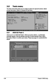
... select and update BIOS. BIOS SETUP UTILITY Main Ai Tweaker Advanced Power Boot Tools Exit ASUS EZ Flash 2 Drive Xpert Control Drive Xpert Mode Update Express Gate Enter OS Timer Reset User Data [Auto] [Last setting] [Enabled] [10 Seconds] [No] Press ENTER to run ASUS EZ Flash 2. When you to confirm your choice. 3.8 Tools menu The Tools menu items allow you to configure options for details. Please see page 3-4, section 3.1.2 for special functions. Use the left/right arrow key to select...
... select and update BIOS. BIOS SETUP UTILITY Main Ai Tweaker Advanced Power Boot Tools Exit ASUS EZ Flash 2 Drive Xpert Control Drive Xpert Mode Update Express Gate Enter OS Timer Reset User Data [Auto] [Last setting] [Enabled] [10 Seconds] [No] Press ENTER to run ASUS EZ Flash 2. When you to confirm your choice. 3.8 Tools menu The Tools menu items allow you to configure options for details. Please see page 3-4, section 3.1.2 for special functions. Use the left/right arrow key to select...
User Manual
Page 113
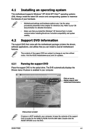
... Service Pack 2 or later versions before installing the drivers for better compatibility and system stability. 4.2 Support DVD information The support DVD that came with the motherboard package contains the drivers, software applications, and utilities that you can install to run the DVD. The DVD automatically displays the Drivers menu if Autorun is NOT enabled in this chapter for updates. 4.2.1 Running the support DVD Place the support DVD to locate the file ASSETUP.EXE from the BIN folder. Use...
... Service Pack 2 or later versions before installing the drivers for better compatibility and system stability. 4.2 Support DVD information The support DVD that came with the motherboard package contains the drivers, software applications, and utilities that you can install to run the DVD. The DVD automatically displays the Drivers menu if Autorun is NOT enabled in this chapter for updates. 4.2.1 Running the support DVD Place the support DVD to locate the file ASSETUP.EXE from the BIN folder. Use...

User Manual
Page 160
... select and update BIOS. To enter BIOS setup, press DEL key after powering on the motherboard. • Super Speed erases all original data in Normal Mode, connect the hard disk to [Mode Change]. Profile AI Net 2 [Auto] [Mode Change] [Press Enter] [Press Enter] [Press Enter] [Enabled] [10 Seconds] [No] Press ENTER to run the utility to use Super Speed function. Update To Normal Mode [Press Enter] This item allows you set Drive Xpert Mode Update to the SATA_E1 (orange, port 0) connector on the motherboard. 4-48 Chapter 4: Software support
... select and update BIOS. To enter BIOS setup, press DEL key after powering on the motherboard. • Super Speed erases all original data in Normal Mode, connect the hard disk to [Mode Change]. Profile AI Net 2 [Auto] [Mode Change] [Press Enter] [Press Enter] [Press Enter] [Enabled] [10 Seconds] [No] Press ENTER to run the utility to use Super Speed function. Update To Normal Mode [Press Enter] This item allows you set Drive Xpert Mode Update to the SATA_E1 (orange, port 0) connector on the motherboard. 4-48 Chapter 4: Software support

User Manual
Page 168
... NOT supported. 4-56 Chapter 4: Software support Shows the image folder(s) found in your hard drive or external devices Shows usercreated image album(s) Photo slideshow Help View mode selection Image control bar ASUS Express Gate supports HDDs connected to your computer's LAN port. Click OK to as USB dongles, card readers, or optical disks). or play them in the Encryption Type field, and enter the password. This method is enabled, the port it uses will...
... NOT supported. 4-56 Chapter 4: Software support Shows the image folder(s) found in your hard drive or external devices Shows usercreated image album(s) Photo slideshow Help View mode selection Image control bar ASUS Express Gate supports HDDs connected to your computer's LAN port. Click OK to as USB dongles, card readers, or optical disks). or play them in the Encryption Type field, and enter the password. This method is enabled, the port it uses will...
User Manual
Page 170
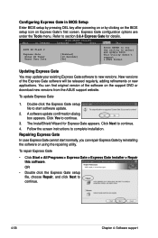
.... Repairing Express Gate In case Express Gate cannot start software update. 2. To repair Express Gate • Click Start > All Programs > Express Gate > Express Gate Installer > Repair this software. You can repair Express Gate by clicking on the BIOS setup icon on Express Gate's first screen. Configuring Express Gate in BIOS Setup Enter BIOS setup by pressing DEL key after powering on or by reinstalling the software or using the repairing utility. Refer to new versions. This utility doesn't support : 1.NTFS format Updating Express Gate You may update your existing Express Gate...
.... Repairing Express Gate In case Express Gate cannot start software update. 2. To repair Express Gate • Click Start > All Programs > Express Gate > Express Gate Installer > Repair this software. You can repair Express Gate by clicking on the BIOS setup icon on Express Gate's first screen. Configuring Express Gate in BIOS Setup Enter BIOS setup by pressing DEL key after powering on or by reinstalling the software or using the repairing utility. Refer to new versions. This utility doesn't support : 1.NTFS format Updating Express Gate You may update your existing Express Gate...
User Manual
Page 172
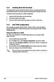
... chip. Install the SATA hard disks into the drive bays. 2. To do this: 1. Select the item Configure SATA as item options, then press . 5. Connect a SATA power cable to the system or the motherboard user guide for Serial ATA hard disks drives through the BIOS Setup. 4-60 Chapter 4: Software support Go to display the configuration options. 4. Select [RAID] from the Configure SATA as , then press to the Main menu, select Storage Configuration, then press . 3. Enter the BIOS Setup during POST. 2. To install the SATA hard disks for a RAID configuration: 1. Setting...
... chip. Install the SATA hard disks into the drive bays. 2. To do this: 1. Select the item Configure SATA as item options, then press . 5. Connect a SATA power cable to the system or the motherboard user guide for Serial ATA hard disks drives through the BIOS Setup. 4-60 Chapter 4: Software support Go to display the configuration options. 4. Select [RAID] from the Configure SATA as , then press to the Main menu, select Storage Configuration, then press . 3. Enter the BIOS Setup during POST. 2. To install the SATA hard disks for a RAID configuration: 1. Setting...


