User Manual
Page 25
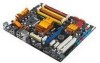
PWR Ground Reset Ground 10-1 pin IDE_LED RESET PWRSW * Requires an ATX power supply. 紅色 1 表示 PIN1 的位置 PLED+ PLEDPWR GND IDELED+ IDELED- SPEAKER、RESET 與 PWRSW IDE_LED 與 PLED PIN1 PIN1 4 ...
PWR Ground Reset Ground 10-1 pin IDE_LED RESET PWRSW * Requires an ATX power supply. 紅色 1 表示 PIN1 的位置 PLED+ PLEDPWR GND IDELED+ IDELED- SPEAKER、RESET 與 PWRSW IDE_LED 與 PLED PIN1 PIN1 4 ...
User Manual
Page 26
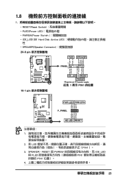
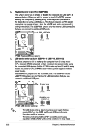
2. Asus Q-Connector 華碩 Q-Connector Q-Connector Q-Connector Q-Connector 1.9 24-pin 或 20-pin 24-pin 4-pin 的 ATX+12V 連接 ATX12V 24-pin ATX 20- pin ATX 26
2. Asus Q-Connector 華碩 Q-Connector Q-Connector Q-Connector Q-Connector 1.9 24-pin 或 20-pin 24-pin 4-pin 的 ATX+12V 連接 ATX12V 24-pin ATX 20- pin ATX 26
User Manual
Page 14
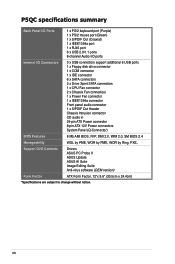
xiv P5QC specifications summary Back Panel I/O Ports 1 x PS/2 keyboard port (Purple) 1 x PS/2 mouse port (Green) 1 x ...x IEEE1394a connector Front panel audio connector 1 x S/PDIF Out Header Chassis Intrusion connector CD audio in 24-pin ATX Power connector 8-pin ATX 12V Power connectors System Panel (Q-Connector) BIOS Features 8 Mb AMI BIOS, PnP, DMI 2.0, WfM 2.0, SM ... by PME, WOR by Ring, PXE, Support DVD Contents Drivers ASUS PC Probe II ASUS Update ASUS AI Suite Image-Editing Suite Anti-virus software (OEM version) Form Factor ATX Form Factor, 12"x 9.6" (30.5cm x 24.4cm) *...
xiv P5QC specifications summary Back Panel I/O Ports 1 x PS/2 keyboard port (Purple) 1 x PS/2 mouse port (Green) 1 x ...x IEEE1394a connector Front panel audio connector 1 x S/PDIF Out Header Chassis Intrusion connector CD audio in 24-pin ATX Power connector 8-pin ATX 12V Power connectors System Panel (Q-Connector) BIOS Features 8 Mb AMI BIOS, PnP, DMI 2.0, WfM 2.0, SM ... by PME, WOR by Ring, PXE, Support DVD Contents Drivers ASUS PC Probe II ASUS Update ASUS AI Suite Image-Editing Suite Anti-virus software (OEM version) Form Factor ATX Form Factor, 12"x 9.6" (30.5cm x 24.4cm) *...
User Manual
Page 27
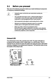
.... The illustration below shows the location of the following precautions before you install motherboard components or change any motherboard settings. • Unplug the power cord from the power supply. ASUS P5QC 2-1 Failure to do so may cause severe damage to avoid touching the ICs on them. • Whenever you uninstall ... a safely grounded object or a metal object, such as the power supply case, before removing or plugging in any component, ensure that the ATX power supply is switched off or the power cord is ON, in sleep mode, or in soft‑off mode. 2.1 Before you proceed ...
.... The illustration below shows the location of the following precautions before you install motherboard components or change any motherboard settings. • Unplug the power cord from the power supply. ASUS P5QC 2-1 Failure to do so may cause severe damage to avoid touching the ICs on them. • Whenever you uninstall ... a safely grounded object or a metal object, such as the power supply case, before removing or plugging in any component, ensure that the ATX power supply is switched off or the power cord is ON, in sleep mode, or in soft‑off mode. 2.1 Before you proceed ...
User Manual
Page 29
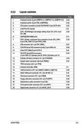
... [orange, port 0]; System panel connector (20-8 pin PANEL) 14. IEEE 1394a port connector (10-1 pin IE1394_2) 18. Front panel audio connector (10-1 pin AAFP) 22. ATX power connectors (24-pin EATXPWR, 8-pin EATX12V) 4. IDE connector (40-1 pin PRI_EIDE) 9. Onboard LED (SB_PWR) 16. Keyboard power (3-pin USBPW1-4, USBPW7-10, USBPW1112) 2. CPU / Northbridge.... Digital audio connector (4-1 pin SPDIF_OUT) Page 2-22 2-22 2-35 2-6 2-23 2-11 2-32 2-27 2-28 2-21 2-29 2-33 2-37 2-1 2-30 2-31 2-33 2-26 2-36 2-34 2-36 ASUS P5QC 2-3
... [orange, port 0]; System panel connector (20-8 pin PANEL) 14. IEEE 1394a port connector (10-1 pin IE1394_2) 18. Front panel audio connector (10-1 pin AAFP) 22. ATX power connectors (24-pin EATXPWR, 8-pin EATX12V) 4. IDE connector (40-1 pin PRI_EIDE) 9. Onboard LED (SB_PWR) 16. Keyboard power (3-pin USBPW1-4, USBPW7-10, USBPW1112) 2. CPU / Northbridge.... Digital audio connector (4-1 pin SPDIF_OUT) Page 2-22 2-22 2-35 2-6 2-23 2-11 2-32 2-27 2-28 2-21 2-29 2-33 2-37 2-1 2-30 2-31 2-33 2-26 2-36 2-34 2-36 ASUS P5QC 2-3
User Manual
Page 48
...; The total current consumed must NOT exceed the power supply capability (+5VSB) whether under normal condition or in reduced power mode). This feature requires an ATX power supply that can wake up from S1 sleep mode (CPU stopped, DRAM refreshed, system running in the BIOS. Set to +5VSB to additional USB...
...; The total current consumed must NOT exceed the power supply capability (+5VSB) whether under normal condition or in reduced power mode). This feature requires an ATX power supply that can wake up from S1 sleep mode (CPU stopped, DRAM refreshed, system running in the BIOS. Set to +5VSB to additional USB...
User Manual
Page 61
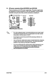
... Calculator at http://support.asus.com/PowerSupplyCalculator/PSCalculator. Find the proper orientation and push down firmly until the connectors completely fit. • For a fully configured system, we recommend that complies with more power-consuming devices. ASUS P5QC 2-35 The system may... become unstable or may not boot up if the power is recommended when configuring a system with ATX 12 V Specification 2.0 (or later version) and provides a minimum power of ...
... Calculator at http://support.asus.com/PowerSupplyCalculator/PSCalculator. Find the proper orientation and push down firmly until the connectors completely fit. • For a fully configured system, we recommend that complies with more power-consuming devices. ASUS P5QC 2-35 The system may... become unstable or may not boot up if the power is recommended when configuring a system with ATX 12 V Specification 2.0 (or later version) and provides a minimum power of ...
User Manual
Page 63
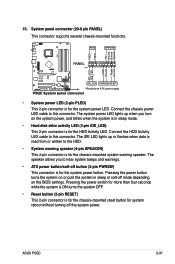
... cable to hear system beeps and warnings. • ATX power button/soft-off mode depending on or puts the system in sleep mode. • Hard disk drive activity LED (2-pin IDE_LED) This 2-pin connector is read from or written to this connector. ASUS P5QC 2-37 15. The speaker allows you turn on the...
... cable to hear system beeps and warnings. • ATX power button/soft-off mode depending on or puts the system in sleep mode. • Hard disk drive activity LED (2-pin IDE_LED) This 2-pin connector is read from or written to this connector. ASUS P5QC 2-37 15. The speaker allows you turn on the...
User Manual
Page 65
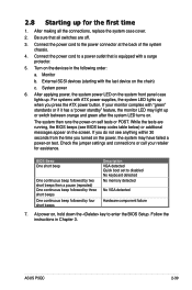
... No keyboard detected No memory detected No VGA detected Hardware component failure 7. Check the jumper settings and connections or call your monitor complies with ATX power supplies, the system LED lights up when you turned on the power, the system may light up or switch between orange and green... the last device on test. If your retailer for the first time 1. Monitor b. After applying power, the system power LED on the screen. ASUS P5QC 2-39 Turn on . After making all switches are running, the BIOS beeps (see anything within 30 seconds from the time you press the...
... No keyboard detected No memory detected No VGA detected Hardware component failure 7. Check the jumper settings and connections or call your monitor complies with ATX power supplies, the system LED lights up when you turned on the power, the system may light up or switch between orange and green... the last device on test. If your retailer for the first time 1. Monitor b. After applying power, the system power LED on the screen. ASUS P5QC 2-39 Turn on . After making all switches are running, the BIOS beeps (see anything within 30 seconds from the time you press the...

User Manual
Page 98
...ºF] MB Temperature [xxxºC/xxxºF] The onboard hardware monitor automatically detects and displays the motherboard and CPU temperatures. CPU Fan Speed [xxxxRPM] or [Ignored] / [N/A] The onboard hardware monitor...Chapter 3: BIOS setup If the fan is not connected to set the appropriate performance level of the ASUS Q-Fan. Set this item to [Silent] to minimize fan speed for quiet CPU fan operation, or... [Turbo] to achieve maximum CPU fan speed. This feature requires an ATX power supply that provides at least 1A on the +5VSB lead. Change Field F1 General...
...ºF] MB Temperature [xxxºC/xxxºF] The onboard hardware monitor automatically detects and displays the motherboard and CPU temperatures. CPU Fan Speed [xxxxRPM] or [Ignored] / [N/A] The onboard hardware monitor...Chapter 3: BIOS setup If the fan is not connected to set the appropriate performance level of the ASUS Q-Fan. Set this item to [Silent] to minimize fan speed for quiet CPU fan operation, or... [Turbo] to achieve maximum CPU fan speed. This feature requires an ATX power supply that provides at least 1A on the +5VSB lead. Change Field F1 General...

