
User Manual
Page 1
Motherboard
Motherboard

User Manual
Page 1
P5KPL-AM Motherboard
P5KPL-AM Motherboard
User Manual
Page 3
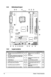
Contents Notices...vi Safety information vii About this guide vii P5KPL-AM specifications summary ix Chapter 1: Product introduction 1.1 Welcome 1-1 1.2 Package contents 1-1 1.3 Special features 1-1 1.3.1 Product highlights 1-1 1.3.2 Innovative ASUS features 1-3 1.4 Before you proceed 1-4 1.5 Motherboard overview 1-5 1.5.1 1.5.2 1.5.3 1.5.4 Placement direction 1-5 Screw holes 1-5 Motherboard layout 1-6 Layout contents 1-6 1.6 Central Processing Unit (CPU 1-7 1.6.1 1.6.2 1.6.3 Installing the CPU 1-7 Installing the CPU heatsink and fan 1-10...
Contents Notices...vi Safety information vii About this guide vii P5KPL-AM specifications summary ix Chapter 1: Product introduction 1.1 Welcome 1-1 1.2 Package contents 1-1 1.3 Special features 1-1 1.3.1 Product highlights 1-1 1.3.2 Innovative ASUS features 1-3 1.4 Before you proceed 1-4 1.5 Motherboard overview 1-5 1.5.1 1.5.2 1.5.3 1.5.4 Placement direction 1-5 Screw holes 1-5 Motherboard layout 1-6 Layout contents 1-6 1.6 Central Processing Unit (CPU 1-7 1.6.1 1.6.2 1.6.3 Installing the CPU 1-7 Installing the CPU heatsink and fan 1-10...
User Manual
Page 6
... the party responsible for compliance could void the user's authority to operate this equipment does cause harmful interference to radio communications. DO NOT throw the motherboard in municipal waste. Check local regulations for help. This class B digital apparatus complies with manufacturer's instructions, may cause harmful interference to radio or television reception...
... the party responsible for compliance could void the user's authority to operate this equipment does cause harmful interference to radio communications. DO NOT throw the motherboard in municipal waste. Check local regulations for help. This class B digital apparatus complies with manufacturer's instructions, may cause harmful interference to radio or television reception...
User Manual
Page 7
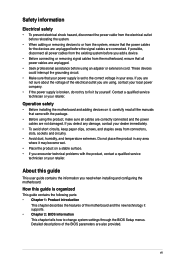
... any damage, contact your dealer immediately. • To avoid short circuits, keep paper clips, screws, and staples away from the motherboard, ensure that came with the product, contact a qualified service technician or your retailer. Do not place the product in your area.... this guide is organized This guide contains the following parts: • Chapter 1: Product introduction This chapter describes the features of the motherboard and the new technology it by yourself. Contact a qualified service technician or your retailer. If you encounter technical problems with the package...
... any damage, contact your dealer immediately. • To avoid short circuits, keep paper clips, screws, and staples away from the motherboard, ensure that came with the product, contact a qualified service technician or your retailer. Do not place the product in your area.... this guide is organized This guide contains the following parts: • Chapter 1: Product introduction This chapter describes the features of the motherboard and the new technology it by yourself. Contact a qualified service technician or your retailer. If you encounter technical problems with the package...
User Manual
Page 11
... DVD User Manual If any of the above items is in the long line of Hazardous Substances (RoHS). ASUS P5KPL-AM 1-1 Chapter 1 Product introduction 1.1 Welcome! The motherboard delivers a host of new features and latest technologies, making it , check the items in your package with the list below. 1.2 Package contents Check your retailer. 1.3 1.3.1 ...
... DVD User Manual If any of the above items is in the long line of Hazardous Substances (RoHS). ASUS P5KPL-AM 1-1 Chapter 1 Product introduction 1.1 Welcome! The motherboard delivers a host of new features and latest technologies, making it , check the items in your package with the list below. 1.2 Package contents Check your retailer. 1.3 1.3.1 ...
User Manual
Page 12
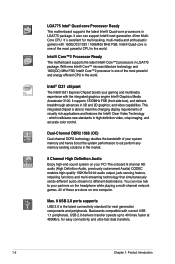
Intel® Core™2 Processor Ready This motherboard supports the latest Intel® Core™2 processors in LGA775 package. Intel® G31 chipset The Intel® G31 Express Chipset boosts your PC! This integrated chipset is the latest connectivity standard for multi-tasking, multi-...high-end sound system on one of the most powerful and energy efficient CPU in the world. LGA775 Intel® Quad-core Processor Ready This motherboard supports the latest Intel® Quad-core processors in LGA775 package. It also can now talk to 40 times faster at 480Mb/s, for easy...
Intel® Core™2 Processor Ready This motherboard supports the latest Intel® Core™2 processors in LGA775 package. Intel® G31 chipset The Intel® G31 Express Chipset boosts your PC! This integrated chipset is the latest connectivity standard for multi-tasking, multi-...high-end sound system on one of the most powerful and energy efficient CPU in the world. LGA775 Intel® Quad-core Processor Ready This motherboard supports the latest Intel® Quad-core processors in LGA775 package. It also can now talk to 40 times faster at 480Mb/s, for easy...
User Manual
Page 13
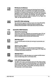
... tool that allows you to work in applications such as 3D gaming. ASUS EZ Flash 2 ASUS EZ Flash 2 is a utility that contains the BIOS file. eliminates the need to their default settings. C.P.R. ASUS P5KPL-AM 1-3 ASUS MyLogo2™ Turn your favorite photos into 256-color boot logos to ... interface creates new usages on desktop PCs e.g., Gigabit LAN, 1394b, and high-speed RAID systems. Serial ATA 3 Gb/s technology This motherboard supports hard drives based on the Serial ATA (SATA) 3Gb/s storage specifications, delivering enhanced scalability and doubling the bus bandwidth for high-...
... tool that allows you to work in applications such as 3D gaming. ASUS EZ Flash 2 ASUS EZ Flash 2 is a utility that contains the BIOS file. eliminates the need to their default settings. C.P.R. ASUS P5KPL-AM 1-3 ASUS MyLogo2™ Turn your favorite photos into 256-color boot logos to ... interface creates new usages on desktop PCs e.g., Gigabit LAN, 1394b, and high-speed RAID systems. Serial ATA 3 Gb/s technology This motherboard supports hard drives based on the Serial ATA (SATA) 3Gb/s storage specifications, delivering enhanced scalability and doubling the bus bandwidth for high-...

User Manual
Page 14
... components. 1.4 Before you proceed Take note of the onboard LED. Onboard LED The motherboard comes with the component. • Before you install or remove any component, ensure that you install motherboard components or change any motherboard component. P5KPL-AM SB_PWR P5KPL-AM Onboard LED ON Standby Power OFF Powered Off 1-4 Chapter 1: Product introduction Failure to...
... components. 1.4 Before you proceed Take note of the onboard LED. Onboard LED The motherboard comes with the component. • Before you install or remove any component, ensure that you install motherboard components or change any motherboard component. P5KPL-AM SB_PWR P5KPL-AM Onboard LED ON Standby Power OFF Powered Off 1-4 Chapter 1: Product introduction Failure to...
User Manual
Page 15
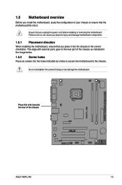
... below. 1.5.2 Screw holes Place six screws into the chassis in the correct orientation. Place this side towards the rear of the chassis P5KPL-AM ASUS P5KPL-AM 1-5 Ensure that you place it . Failure to do so can damage the motherboard. Do not overtighten the screws! Doing so can cause you physical injury and damage...
... below. 1.5.2 Screw holes Place six screws into the chassis in the correct orientation. Place this side towards the rear of the chassis P5KPL-AM ASUS P5KPL-AM 1-5 Ensure that you place it . Failure to do so can damage the motherboard. Do not overtighten the screws! Doing so can cause you physical injury and damage...
User Manual
Page 16
.... LGA775 CPU socket 1-7 11. System panel connector (10-1 pin F_PANEL) 1-28 16. IDE connector (40-1 pin PRI_IDE) 1-23 14. CPU_FAN Super I/O 1.5.3 Motherboard layout 12 3 20.3cm (8in) PS/2KBMS T: Mouse B: Keyboard COM1 ATX12V LGA775 2 4 2 CHA_FAN FLOPPY DDR2 DIMM1 (64 bit,240-pin module) DDR2 ...(64 bit,240-pin module) PARALLEL PORT 5 VGA1 USB34 PWR_FAN EATXPWR 24.4cm(9.6in) P5KPL-AM LAN1_USB12 Intel G31 6 RTM870T-954 AUDIO PRI_IDE RTL 8102EL PCIEX1_1 PCIEX16 PCI1 1 Intel ICH7 CR2032 3V Lithium Cell CMOS Power VT1708B SPDIF_OUT AAFP 16 15 14 PCI2 USB78 CD ...
.... LGA775 CPU socket 1-7 11. System panel connector (10-1 pin F_PANEL) 1-28 16. IDE connector (40-1 pin PRI_IDE) 1-23 14. CPU_FAN Super I/O 1.5.3 Motherboard layout 12 3 20.3cm (8in) PS/2KBMS T: Mouse B: Keyboard COM1 ATX12V LGA775 2 4 2 CHA_FAN FLOPPY DDR2 DIMM1 (64 bit,240-pin module) DDR2 ...(64 bit,240-pin module) PARALLEL PORT 5 VGA1 USB34 PWR_FAN EATXPWR 24.4cm(9.6in) P5KPL-AM LAN1_USB12 Intel G31 6 RTM870T-954 AUDIO PRI_IDE RTL 8102EL PCIEX1_1 PCIEX16 PCI1 1 Intel ICH7 CR2032 3V Lithium Cell CMOS Power VT1708B SPDIF_OUT AAFP 16 15 14 PCI2 USB78 CD ...
User Manual
Page 17
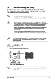
...ASUS P5KPL-AM 1-7 Locate the CPU socket on the socket and the socket contacts are not bent. ASUS will shoulder the cost of repair only if the damage is facing towards you see any damage to the PnP cap/socket contacts/motherboard components. The motherboard supports Intel® LGA775 processors with the Intel...or if you and the load lever is on the motherboard. 1.6 Central Processing Unit (CPU) The motherboard comes with a surface mount LGA775 socket designed for the Intel® Core™2 Quad / Core™2 Extreme / Core™2 Duo / Pentium® D / Pentium® 4 and...
...ASUS P5KPL-AM 1-7 Locate the CPU socket on the socket and the socket contacts are not bent. ASUS will shoulder the cost of repair only if the damage is facing towards you see any damage to the PnP cap/socket contacts/motherboard components. The motherboard supports Intel® LGA775 processors with the Intel...or if you and the load lever is on the motherboard. 1.6 Central Processing Unit (CPU) The motherboard comes with a surface mount LGA775 socket designed for the Intel® Core™2 Quad / Core™2 Extreme / Core™2 Duo / Pentium® D / Pentium® 4 and...
User Manual
Page 20
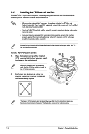
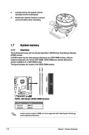
...heatsink and fan. • Your Intel® LGA775 heatsink and fan assembly comes in a push-pin design and requires no tool to install. • If you purchased a separate CPU heatsink and fan assembly, ensure that you have installed the motherboard to secure the heatsink and fan... assembly in a diagonal sequence to the chassis before you buy a boxed Intel® processor, the package includes the CPU fan and heatsink assembly. The illustration above...
...heatsink and fan. • Your Intel® LGA775 heatsink and fan assembly comes in a push-pin design and requires no tool to install. • If you purchased a separate CPU heatsink and fan assembly, ensure that you have installed the motherboard to secure the heatsink and fan... assembly in a diagonal sequence to the chassis before you buy a boxed Intel® processor, the package includes the CPU fan and heatsink assembly. The illustration above...
User Manual
Page 21
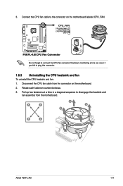
...fan cable from the motherboard. A B A B B A B A ASUS P5KPL-AM 1-11 Connect the CPU fan cable to disengage the heatsink and fan assembly from the connector on the motherboard labeled CPU_FAN. Pull up two fasteners at a time in a diagonal sequence to the connector on the motherboard. 2. 3. Hardware monitoring... errors can occur if you fail to connect the CPU fan connector! CPU_FAN CPU FAN PWM CPU FAN IN CPU FAN PWR GND P5KPL-AM P5KPL-AM CPU Fan Connector Do not forget to plug...
...fan cable from the motherboard. A B A B B A B A ASUS P5KPL-AM 1-11 Connect the CPU fan cable to disengage the heatsink and fan assembly from the connector on the motherboard labeled CPU_FAN. Pull up two fasteners at a time in a diagonal sequence to the connector on the motherboard. 2. 3. Hardware monitoring... errors can occur if you fail to connect the CPU fan connector! CPU_FAN CPU FAN PWM CPU FAN IN CPU FAN PWR GND P5KPL-AM P5KPL-AM CPU Fan Connector Do not forget to plug...
User Manual
Page 22
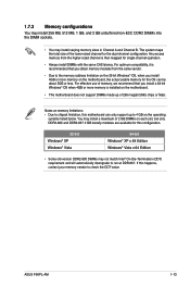
...-pin footprint compared to support the Intel® Quiet System Technology and for optimum performance. 1-12 Chapter 1: Product introduction Carefully remove the heatsink and fan assembly from the motherboard. 5. The figure illustrates the location of the DDR2 DIMM sockets: DIMM_A1 DIMM_B1 128 Pins P5KPL-AM 112 Pins P5KPL-AM 240-pin DDR2 DIMM Sockets...
...-pin footprint compared to support the Intel® Quiet System Technology and for optimum performance. 1-12 Chapter 1: Product introduction Carefully remove the heatsink and fan assembly from the motherboard. 5. The figure illustrates the location of the DDR2 DIMM sockets: DIMM_A1 DIMM_B1 128 Pins P5KPL-AM 112 Pins P5KPL-AM 240-pin DDR2 DIMM Sockets...
User Manual
Page 23
...more memory is then mapped for the OS can only support up of 2 GB DIMMs on the motherboard. • This motherboard does not support DIMMs made up to check the ODT value. ASUS P5KPL-AM 1-13 Notes on memory limitations • Due to chipset limitation, this configuration. 32-bit ...Windows® XP Windows® Vista 64-bit Windows® XP x 64 Edition Windows® Vista x 64 Edition • Some old-version DDR2-800 DIMMs may not match Intel®...
...more memory is then mapped for the OS can only support up of 2 GB DIMMs on the motherboard. • This motherboard does not support DIMMs made up to check the ODT value. ASUS P5KPL-AM 1-13 Notes on memory limitations • Due to chipset limitation, this configuration. 32-bit ...Windows® XP Windows® Vista 64-bit Windows® XP x 64 Edition Windows® Vista x 64 Edition • Some old-version DDR2-800 DIMMs may not match Intel®...
User Manual
Page 27
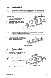
... the notch on the DIMM matches the break on the socket. 1 2 DDR2 DIMM notch 1 Unlocked retaining clip A DDR2 DIMM is properly seated. DDR2 DIMM notch ASUS P5KPL-AM 1-17 Remove the DIMM from the socket. Simultaneously press the retaining clips outward to both the motherboard and the components.
... the notch on the DIMM matches the break on the socket. 1 2 DDR2 DIMM notch 1 Unlocked retaining clip A DDR2 DIMM is properly seated. DDR2 DIMM notch ASUS P5KPL-AM 1-17 Remove the DIMM from the socket. Simultaneously press the retaining clips outward to both the motherboard and the components.
User Manual
Page 28
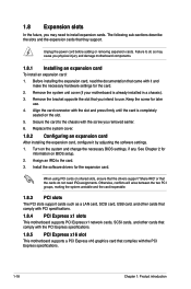
...a LAN card, SCSI card, USB card, and other cards that comply with PCI specifications. 1.8.4 PCI Express x1 slots This motherboard supports PCI Express x1 network cards, SCSI cards, and other cards that comply with the PCI Express specifications. 1.8.5 PCI Express x16 slot This.... 1-18 Chapter 1: Product introduction Turn on shared slots, ensure that the drivers support "Share IRQ" or that you physical injury and damage motherboard components. 1.8.1 Installing an expansion card To install an expansion card: 1. Install the software drivers for information on the slot. 5. When using ...
...a LAN card, SCSI card, USB card, and other cards that comply with PCI specifications. 1.8.4 PCI Express x1 slots This motherboard supports PCI Express x1 network cards, SCSI cards, and other cards that comply with the PCI Express specifications. 1.8.5 PCI Express x16 slot This.... 1-18 Chapter 1: Product introduction Turn on shared slots, ensure that the drivers support "Share IRQ" or that you physical injury and damage motherboard components. 1.8.1 Installing an expansion card To install an expansion card: 1. Install the software drivers for information on the slot. 5. When using ...
User Manual
Page 33
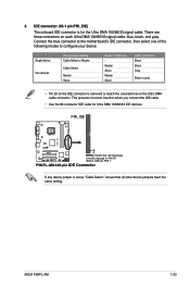
... Master Cable-Select Master Slave Mode of the following modes to match the covered hole on the IDE connector is removed to configure your device. ASUS P5KPL-AM 1-23 IDE connector (40-1 pin PRI_IDE) The onboard IDE connector is set as "Cable-Select," ensure that all other device jumpers have the ...the IDE cable. • Use the 80-conductor IDE cable for the Ultra DMA 100/66/33 signal cable. Connect the blue connector to the motherboard's IDE connector, then select one of device(s) Master Slave Master Slave Cable connector Black Black Gray Black or gray • Pin 20 on the ...
... Master Cable-Select Master Slave Mode of the following modes to match the covered hole on the IDE connector is removed to configure your device. ASUS P5KPL-AM 1-23 IDE connector (40-1 pin PRI_IDE) The onboard IDE connector is set as "Cable-Select," ensure that all other device jumpers have the ...the IDE cable. • Use the 80-conductor IDE cable for the Ultra DMA 100/66/33 signal cable. Connect the blue connector to the motherboard's IDE connector, then select one of device(s) Master Slave Master Slave Cable connector Black Black Gray Black or gray • Pin 20 on the ...
User Manual
Page 34
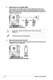
...such as a CD-ROM, TV tuner, or MPEG card. The USB module cable is purchased separately. 6. Doing so will damage the motherboard! Optical drive audio connector (4-pin CD) These connectors allow you to 480 Mbps connection speed. USB+5V USB_P6USB_P6+ GND NC USB+5V ...to a slot opening at the back of these connectors, then install the module to the USB connectors. CD (black) P5KPL-AM Left Audio Channel Ground Ground Right Audio Channel P5KPL-AM Internal Audio Connector 1-24 Chapter 1: Product introduction 5. USB connectors (10-1 pin USB56, USB78) These connectors are...
...such as a CD-ROM, TV tuner, or MPEG card. The USB module cable is purchased separately. 6. Doing so will damage the motherboard! Optical drive audio connector (4-pin CD) These connectors allow you to 480 Mbps connection speed. USB+5V USB_P6USB_P6+ GND NC USB+5V ...to a slot opening at the back of these connectors, then install the module to the USB connectors. CD (black) P5KPL-AM Left Audio Channel Ground Ground Right Audio Channel P5KPL-AM Internal Audio Connector 1-24 Chapter 1: Product introduction 5. USB connectors (10-1 pin USB56, USB78) These connectors are...


