
Motherboard DIY Troubleshooting Guide
Page 3
Features Contents Notices v Safety information vi About this guide vii ASUS contact information viii P4VP-MX specifications summary ix Chapter 1: Product introduction 1.1 Welcome 1-2 1.2 Package contents 1-2 1.3 Special features 1-3 1.4 Motherboard components... 1-17 Chapter 2: BIOS information 2.1 Managing and updating your BIOS 2-2 2.1.1 Creating a bootable floppy disk 2-2 2.1.2 Using AFUDOS to update the BIOS 2-2 2.1.3 Using ASUS EZ Flash to update the BIOS 2-3 2.1.4 Recovering the BIOS with CrashFree BIOS 2 ....... 2-5 2.2 BIOS Setup program 2-6 2.2.1 BIOS menu screen 2-7 iii
Features Contents Notices v Safety information vi About this guide vii ASUS contact information viii P4VP-MX specifications summary ix Chapter 1: Product introduction 1.1 Welcome 1-2 1.2 Package contents 1-2 1.3 Special features 1-3 1.4 Motherboard components... 1-17 Chapter 2: BIOS information 2.1 Managing and updating your BIOS 2-2 2.1.1 Creating a bootable floppy disk 2-2 2.1.2 Using AFUDOS to update the BIOS 2-2 2.1.3 Using ASUS EZ Flash to update the BIOS 2-3 2.1.4 Recovering the BIOS with CrashFree BIOS 2 ....... 2-5 2.2 BIOS Setup program 2-6 2.2.1 BIOS menu screen 2-7 iii
Motherboard DIY Troubleshooting Guide
Page 9
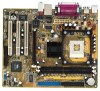
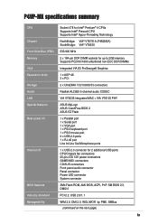
P4VP-MX specifications summary CPU Socket 478 for Intel® Pentium® 4 CPUs Supports Intel® Prescott CPU Supports Intel® Hyper-Threading Technology Chipset NorthBridge: VIA&#... 3 x PCI Storage 2 x UltraDMA 133/100/66/33 connectors Audio Realtek ALC655 6-channel audio CODEC LAN VIA VT8235 integrated MAC + VIA VT6103 PHY Special features ASUS MyLogo ASUS CrashFree BIOS 2 ASUS EZ Flash Rear panel I/O 1 x Parallel port 1 x Serial port 1 x VGA port 1 x PS/2 keyboard port 1 x PS/2 mouse port 4 x USB 2.0 ports 1 x RJ-45 port Line In/Line...
P4VP-MX specifications summary CPU Socket 478 for Intel® Pentium® 4 CPUs Supports Intel® Prescott CPU Supports Intel® Hyper-Threading Technology Chipset NorthBridge: VIA&#... 3 x PCI Storage 2 x UltraDMA 133/100/66/33 connectors Audio Realtek ALC655 6-channel audio CODEC LAN VIA VT8235 integrated MAC + VIA VT6103 PHY Special features ASUS MyLogo ASUS CrashFree BIOS 2 ASUS EZ Flash Rear panel I/O 1 x Parallel port 1 x Serial port 1 x VGA port 1 x PS/2 keyboard port 1 x PS/2 mouse port 4 x USB 2.0 ports 1 x RJ-45 port Line In/Line...
Motherboard DIY Troubleshooting Guide
Page 13
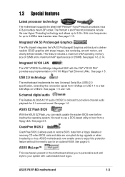
...is onboard to pay for an optional ROM. See page 2-5. ASUS MyLogo™ This new feature present in the motherboard allows you can easily update the system BIOS even before loading the operating system. ASUS P4VP-MX motherboard 1-3 Integrated VIA S3 ProSavage8 Graphics The VIA chipset integrates the...Bus (USB) 2.0 specification, extending the connection speed from a floppy disk. ASUS EZ Flash BIOS With the ASUS EZ Flash, you to personalize and add style to a fast 480 Mbps on USB 2.0. See page 2-3. ASUS motherboards now enable users to enjoy this protection feature without the need to ...
...is onboard to pay for an optional ROM. See page 2-5. ASUS MyLogo™ This new feature present in the motherboard allows you can easily update the system BIOS even before loading the operating system. ASUS P4VP-MX motherboard 1-3 Integrated VIA S3 ProSavage8 Graphics The VIA chipset integrates the...Bus (USB) 2.0 specification, extending the connection speed from a floppy disk. ASUS EZ Flash BIOS With the ASUS EZ Flash, you to personalize and add style to a fast 480 Mbps on USB 2.0. See page 2-3. ASUS motherboards now enable users to enjoy this protection feature without the need to ...
Motherboard DIY Troubleshooting Guide
Page 15
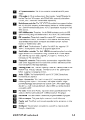
...97 interface and PCI 2.2 interface. 8 Floppy disk connector. This LED acts as a reminder to an ATX power supply. 2 CPU socket. ASUS P4VP-MX motherboard 1-5 This connector accommodates the provided ribbon cable for the Intel® Pentium® 4 Processor, with 533/400 MHz system bus that... transfer rates, respectively. 3 North bridge controller. The Realtek ALC655 is a standby power on the motherboard. This 3Mb firmware contains the programmable BIOS program. 14 PS/2 mouse port. This Low Pin Count (LPC) interface provides the commonly used Super I /O controller. This 25-pin port...
...97 interface and PCI 2.2 interface. 8 Floppy disk connector. This LED acts as a reminder to an ATX power supply. 2 CPU socket. ASUS P4VP-MX motherboard 1-5 This connector accommodates the provided ribbon cable for the Intel® Pentium® 4 Processor, with 533/400 MHz system bus that... transfer rates, respectively. 3 North bridge controller. The Realtek ALC655 is a standby power on the motherboard. This 3Mb firmware contains the programmable BIOS program. 14 PS/2 mouse port. This Low Pin Count (LPC) interface provides the commonly used Super I /O controller. This 25-pin port...
Motherboard DIY Troubleshooting Guide
Page 17
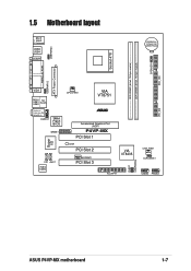
... Top: RJ-45 Top:Line In Center:Line Out Below:Mic In AUDIO1 3Mbit Flash BIOS GAME1 Super I/O CD1 AUX1 Audio Codec CPU_FAN1 VIA VT8751 ® Accelerated Graphics Port (AGP) P4VP-MX PCI Slot 1 LED1 PCI Slot 2 MODEM1 PCI Slot 3 01 23 VIA VT8235 CHA_FAN1 CLRCMOS1 PLED1 USBPWR56 FLOPPY1 USB56 PANEL1 PRI_IDE ASUS P4VP-MX motherboard 1-7
... Top: RJ-45 Top:Line In Center:Line Out Below:Mic In AUDIO1 3Mbit Flash BIOS GAME1 Super I/O CD1 AUX1 Audio Codec CPU_FAN1 VIA VT8751 ® Accelerated Graphics Port (AGP) P4VP-MX PCI Slot 1 LED1 PCI Slot 2 MODEM1 PCI Slot 3 01 23 VIA VT8235 CHA_FAN1 CLRCMOS1 PLED1 USBPWR56 FLOPPY1 USB56 PANEL1 PRI_IDE ASUS P4VP-MX motherboard 1-7
Motherboard DIY Troubleshooting Guide
Page 20
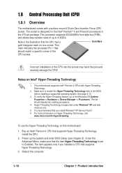
This processor supports 533/400MHz front side bus (FSB), and allows data transfer rates of up the system and enter BIOS Setup (see Chapter 2). Gold Mark Incorrect installation of the CPU socket. Hyper-Threading Technology is recommended that supports Hyper-Threading Technology. .../s. Note in the illustration that the item Hyper-Threading Technology is designed for the Intel® Pentium® 4 and Prescott processors in the BIOS before installing a supported operating system. It is supported under Windows® XP and later versions only. 5. Power up to the Windows OS System...
This processor supports 533/400MHz front side bus (FSB), and allows data transfer rates of up the system and enter BIOS Setup (see Chapter 2). Gold Mark Incorrect installation of the CPU socket. Hyper-Threading Technology is recommended that supports Hyper-Threading Technology. .../s. Note in the illustration that the item Hyper-Threading Technology is designed for the Intel® Pentium® 4 and Prescott processors in the BIOS before installing a supported operating system. It is supported under Windows® XP and later versions only. 5. Power up to the Windows OS System...
Motherboard DIY Troubleshooting Guide
Page 23
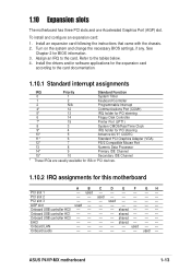
...the system and change the necessary BIOS settings, if any. PCI slot 2 - - PCI slot 3 - - - Onboard USB controller HC3 - - - - shared - - - See Chapter 2 for this motherboard A B C D E F GH PCI slot 1 - shared - - - EHCI - - - - Onboard audio - - - - - - ASUS P4VP-MX motherboard 1-13 Install the drivers...9 Primary IDE Channel 15* 10 Secondary IDE Channel * These IRQs are usually available for ISA or PCI devices. 1.10.2 IRQ assignments for BIOS information. 3. Onboard LAN - - - - - used - - Assign an IRQ to the card. Onboard USB controller HC1 - - ...
...the system and change the necessary BIOS settings, if any. PCI slot 2 - - PCI slot 3 - - - Onboard USB controller HC3 - - - - shared - - - See Chapter 2 for this motherboard A B C D E F GH PCI slot 1 - shared - - - EHCI - - - - Onboard audio - - - - - - ASUS P4VP-MX motherboard 1-13 Install the drivers...9 Primary IDE Channel 15* 10 Secondary IDE Channel * These IRQs are usually available for ISA or PCI devices. 1.10.2 IRQ assignments for BIOS information. 3. Onboard LAN - - - - - used - - Assign an IRQ to the card. Onboard USB controller HC1 - - ...
Motherboard DIY Troubleshooting Guide
Page 25
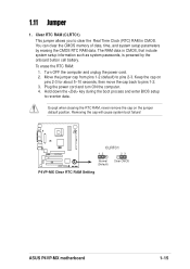
...Keep the cap on the jumper default position. Removing the cap will cause system boot failure! ® P4VP-MX CLRTC1 12 23 Normal (Default) Clear CMOS P4VP-MX Clear RTC RAM Setting ASUS P4VP-MX motherboard 1-15 You can clear the CMOS memory of date, time, and system setup parameters by the ...onboard button cell battery. Plug the power cord and turn ON the computer. 4. Hold down the key during the boot process and enter BIOS...
...Keep the cap on the jumper default position. Removing the cap will cause system boot failure! ® P4VP-MX CLRTC1 12 23 Normal (Default) Clear CMOS P4VP-MX Clear RTC RAM Setting ASUS P4VP-MX motherboard 1-15 You can clear the CMOS memory of date, time, and system setup parameters by the ...onboard button cell battery. Plug the power cord and turn ON the computer. 4. Hold down the key during the boot process and enter BIOS...
Motherboard DIY Troubleshooting Guide
Page 28
...you must configure the second drive as a slave device by setting its jumper accordingly. 3. BIOS supports specific device bootup. Pin 20 on the UltraDMA cable connector. SEC_IDE PRI_IDE ® P4VP-MX NOTE: Orient the red markings on the UltraDMA133/100/66 cable is removed to the hard...secondary IDE connector, then connect the gray connector to the UltraDMA133/100 slave device (hard disk drive) and the black connector to PIN 1 P4VP-MX IDE Connectors PIN 1 PIN 1 4. For UltraDMA133/100/66 IDE devices, use the 80-conductor IDE cable. If you connect non-UltraDMA133/100...
...you must configure the second drive as a slave device by setting its jumper accordingly. 3. BIOS supports specific device bootup. Pin 20 on the UltraDMA cable connector. SEC_IDE PRI_IDE ® P4VP-MX NOTE: Orient the red markings on the UltraDMA133/100/66 cable is removed to the hard...secondary IDE connector, then connect the gray connector to the UltraDMA133/100 slave device (hard disk drive) and the black connector to PIN 1 P4VP-MX IDE Connectors PIN 1 PIN 1 4. For UltraDMA133/100/66 IDE devices, use the 80-conductor IDE cable. If you connect non-UltraDMA133/100...

Motherboard DIY Troubleshooting Guide
Page 32
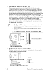
... up . • ATX Power Switch / Soft-Off Switch Lead (2-pin PWR BTN) This connector connects a switch that controls the system power. Ground Reset ® P4VP-MX PANEL1 P4VP-MX Front Panel Audio Connector IDE_LED Reset SW * Requires an ATX power supply. • System Power LED Lead (2-pin PWR LED) This 2-1 pin connector connects to... and write activities of any device connected to the primary or secondary IDE connector cause this LED to light up when you turn on the BIOS or OS settings. 11. ATX Power Power LED Switch* PLED+ PLEDPWR GND IDE_LED+ IDE_LED-
... up . • ATX Power Switch / Soft-Off Switch Lead (2-pin PWR BTN) This connector connects a switch that controls the system power. Ground Reset ® P4VP-MX PANEL1 P4VP-MX Front Panel Audio Connector IDE_LED Reset SW * Requires an ATX power supply. • System Power LED Lead (2-pin PWR LED) This 2-1 pin connector connects to... and write activities of any device connected to the primary or secondary IDE connector cause this LED to light up when you turn on the BIOS or OS settings. 11. ATX Power Power LED Switch* PLED+ PLEDPWR GND IDE_LED+ IDE_LED-

Motherboard DIY Troubleshooting Guide
Page 33
Chapter 2 This chapter tells how to change system settings through the BIOS Setup menus. BIOS information Detailed descriptions of the BIOS parameters are also provided.
Chapter 2 This chapter tells how to change system settings through the BIOS Setup menus. BIOS information Detailed descriptions of the BIOS parameters are also provided.

Motherboard DIY Troubleshooting Guide
Page 34
... the AFUDOS.EXE utility in the support CD. Click on the Startup Disk tab, then on Control Panel. Visit the ASUS website (www.asus.com) to type the exact BIOS file name at the prompt. 2. Copy the AFUDOS.EXE utility from the support CD to the bootable floppy disk that you need to...
... the AFUDOS.EXE utility in the support CD. Click on the Startup Disk tab, then on Control Panel. Visit the ASUS website (www.asus.com) to type the exact BIOS file name at the prompt. 2. Copy the AFUDOS.EXE utility from the support CD to the bootable floppy disk that you need to...

Motherboard DIY Troubleshooting Guide
Page 35
...- Reboot the system from the hard disk. 2.1.3 Using ASUS EZ Flash to update the BIOS The ASUS EZ Flash feature allows you see ASUS contact information on page viii). Download the latest BIOS file from a diskette and using ASUS EZ Flash. 1. Version 1.10 Copyright (C) 2002 American Megatrends... the same as shown. The EZ Flash is built-in the BIOS firmware so it is for reference only. ASUS P4VP-MX motherboard 2-3 Version 1.10 Copyright (C) 2002 American Megatrends, Inc. Reading file ..... The BIOS information on the screen is accessible by simply pressing + during the...
...- Reboot the system from the hard disk. 2.1.3 Using ASUS EZ Flash to update the BIOS The ASUS EZ Flash feature allows you see ASUS contact information on page viii). Download the latest BIOS file from a diskette and using ASUS EZ Flash. 1. Version 1.10 Copyright (C) 2002 American Megatrends... the same as shown. The EZ Flash is built-in the BIOS firmware so it is for reference only. ASUS P4VP-MX motherboard 2-3 Version 1.10 Copyright (C) 2002 American Megatrends, Inc. Reading file ..... The BIOS information on the screen is accessible by simply pressing + during the...

Motherboard DIY Troubleshooting Guide
Page 36
... continue with the update process. When found ." Press to update the BIOS (Y/N)? _ If you see on a piece of paper. Reboot the computer. 3. ASUS EZ Flash V1.00 Copyright (C) 2002, ASUSTeK COMPUTER INC. [Onboard BIOS Information] BIOS Version : ASUS P4VP-MX ACPI BIOS Revision 1001 Beta 003 BIOS Model : P4VP-MX BIOS Built Date : 06/03/03 Please Enter File Name for reference...
... continue with the update process. When found ." Press to update the BIOS (Y/N)? _ If you see on a piece of paper. Reboot the computer. 3. ASUS EZ Flash V1.00 Copyright (C) 2002, ASUSTeK COMPUTER INC. [Onboard BIOS Information] BIOS Version : ASUS P4VP-MX ACPI BIOS Revision 1001 Beta 003 BIOS Model : P4VP-MX BIOS Built Date : 06/03/03 Please Enter File Name for reference...
Motherboard DIY Troubleshooting Guide
Page 37
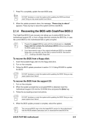
... process. 2. DO NOT shutdown or reset the system while updating the BIOS! Insert the bootable floppy disk into the CD-ROM drive and press the Enter key. 3. Follow the succeeding screen instructions. When the update process is complete, reboot the system. ASUS P4VP-MX motherboard 2-5 7. Press any key to reboot" appears. To recover the...
... process. 2. DO NOT shutdown or reset the system while updating the BIOS! Insert the bootable floppy disk into the CD-ROM drive and press the Enter key. 3. Follow the succeeding screen instructions. When the update process is complete, reboot the system. ASUS P4VP-MX motherboard 2-5 7. Press any key to reboot" appears. To recover the...

Motherboard DIY Troubleshooting Guide
Page 38
... during the Power-On Self Test (POST) to download the latest product and BIOS information. 2-6 Chapter 2: BIOS information Visit the ASUS website (www.asus.com) to enter the Setup utility. This requires you to reconfigure your computer in the future. If you with its test routines. The Setup program ...
... during the Power-On Self Test (POST) to download the latest product and BIOS information. 2-6 Chapter 2: BIOS information Visit the ASUS website (www.asus.com) to enter the Setup utility. This requires you to reconfigure your computer in the future. If you with its test routines. The Setup program ...
Motherboard DIY Troubleshooting Guide
Page 39
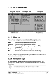
...item is highlighted. 2.2.3 Navigation keys At the bottom right corner of the navigation keys differ from one screen to another. 2.2.1 BIOS menu screen Menu items Menu bar Configuration fields General help System Time System Date Legacy Diskette A Primary IDE Master Primary IDE Slave...+- Use the navigation keys to select items in ] :[ST320413A] :[ASUS CD-S340] :[Not Detected] :[Not Detected] Sub-menu items Use [ENTER], [TAB] or [SHIFT-TAB] to configure system time. Use [+] or [-] to select a field. ASUS P4VP-MX motherboard 2-7 Some of a menu screen are the navigation keys for ...
...item is highlighted. 2.2.3 Navigation keys At the bottom right corner of the navigation keys differ from one screen to another. 2.2.1 BIOS menu screen Menu items Menu bar Configuration fields General help System Time System Date Legacy Diskette A Primary IDE Master Primary IDE Slave...+- Use the navigation keys to select items in ] :[ST320413A] :[ASUS CD-S340] :[Not Detected] :[Not Detected] Sub-menu items Use [ENTER], [TAB] or [SHIFT-TAB] to configure system time. Use [+] or [-] to select a field. ASUS P4VP-MX motherboard 2-7 Some of a menu screen are the navigation keys for ...

Motherboard DIY Troubleshooting Guide
Page 40
... IRQ4 IRQ5 IRQ7 IRQ9 IRQ10 IRQ11 IRQ14 IRQ15 [Available] [Available] [Available] [Available] [Available] [Available] [Available] [Available] [Available] NO: Lets the BIOS configure all the devices in the system. You can not select an item that do not fit on the screen. Advanced PCI/PnP settings WARNING... to display a list of a menu screen when there are items that is highlighted when selected. A configurable field is enclosed in ] :[ST320413A] :[ASUS CD-S340] :[Not Detected] :[Not Detected] Main menu items Use [ENTER], [TAB] or [SHIFT-TAB] to configure system time. Press Up...
... IRQ4 IRQ5 IRQ7 IRQ9 IRQ10 IRQ11 IRQ14 IRQ15 [Available] [Available] [Available] [Available] [Available] [Available] [Available] [Available] [Available] NO: Lets the BIOS configure all the devices in the system. You can not select an item that do not fit on the screen. Advanced PCI/PnP settings WARNING... to display a list of a menu screen when there are items that is highlighted when selected. A configurable field is enclosed in ] :[ST320413A] :[ASUS CD-S340] :[Not Detected] :[Not Detected] Main menu items Use [ENTER], [TAB] or [SHIFT-TAB] to configure system time. Press Up...

Motherboard DIY Troubleshooting Guide
Page 41
... IDE Slave System Information [11:10:19] [Thu 05/27/2003] [1.44M, 3.5 in .] ASUS P4VP-MX motherboard 2-9 Configuration options: [Disabled] [360K, 5.25 in.] [1.2M , 5.25 in.] [720K , 3.5 in.] [1.44M, 3.5 in.] [2.88M, 3.5 in ] :[ST320413A] :[ASUS CD-S340] :[Not Detected] :[Not Detected] Use [ENTER], [TAB] or [SHIFT-TAB] to...date. 2.3.3 Legacy Diskette A, B [1.44M, 3.5 in.] Sets the type of the basic system information. 2.3 Main menu When you enter the BIOS Setup program, the Main menu screen appears giving you to set the system time. 2.3.2 System Date [Day xx/xx/xxxx] This item allows...
... IDE Slave System Information [11:10:19] [Thu 05/27/2003] [1.44M, 3.5 in .] ASUS P4VP-MX motherboard 2-9 Configuration options: [Disabled] [360K, 5.25 in.] [1.2M , 5.25 in.] [720K , 3.5 in.] [1.44M, 3.5 in.] [2.88M, 3.5 in ] :[ST320413A] :[ASUS CD-S340] :[Not Detected] :[Not Detected] Use [ENTER], [TAB] or [SHIFT-TAB] to...date. 2.3.3 Legacy Diskette A, B [1.44M, 3.5 in.] Sets the type of the basic system information. 2.3 Main menu When you enter the BIOS Setup program, the Main menu screen appears giving you to set the system time. 2.3.2 System Date [Day xx/xx/xxxx] This item allows...

Motherboard DIY Troubleshooting Guide
Page 42
...items (Device, Vendor, Size, LBA Mode, Block Mode, PIO Mode, Async DMA, Ultra DMA, and SMART monitoring) are autodetected by BIOS and are not user-configurable. Type [Auto] Selects the type of device connected to the system. When set to Disabled, the data ...of IDE drive. Select Screen Select Item +- 2.3.4 Primary/Secondary IDE Master/Slave While entering Setup, BIOS auto-detects the presence of IDE devices. Configuration options: [Auto] [0] [1] [2] [3] [4] 2-10 Chapter 2: BIOS information Select a device item then press Enter to Auto enables the LBA mode if the device supports...
...items (Device, Vendor, Size, LBA Mode, Block Mode, PIO Mode, Async DMA, Ultra DMA, and SMART monitoring) are autodetected by BIOS and are not user-configurable. Type [Auto] Selects the type of device connected to the system. When set to Disabled, the data ...of IDE drive. Select Screen Select Item +- 2.3.4 Primary/Secondary IDE Master/Slave While entering Setup, BIOS auto-detects the presence of IDE devices. Configuration options: [Auto] [0] [1] [2] [3] [4] 2-10 Chapter 2: BIOS information Select a device item then press Enter to Auto enables the LBA mode if the device supports...


