Motherboard DIY Troubleshooting Guide
Page 1
Motherboard P4VP-MX User Guide
Motherboard P4VP-MX User Guide

Motherboard DIY Troubleshooting Guide
Page 3
... v Safety information vi About this guide vii ASUS contact information viii P4VP-MX specifications summary ix Chapter 1: Product introduction 1.1 Welcome 1-2 1.2 Package contents 1-2 1.3 Special features 1-3 1.4 Motherboard components 1-4 1.5 Motherboard layout 1-7 1.6 Before you proceed 1-8 1.7 Motherboard installation 1-9 1.7.1 Placement direction 1-9 1.7.2 Screw ...DIMM 1-12 1.10 Expansion slots 1-13 1.10.1 Standard interrupt assignments 1-13 1.10.2 IRQ assignments for this motherboard 1-13 1.10.3 PCI slots 1-14 1.10.4 AGP slot 1-14 1.11 Jumper 1-15 1.12 Connectors 1-17...
... v Safety information vi About this guide vii ASUS contact information viii P4VP-MX specifications summary ix Chapter 1: Product introduction 1.1 Welcome 1-2 1.2 Package contents 1-2 1.3 Special features 1-3 1.4 Motherboard components 1-4 1.5 Motherboard layout 1-7 1.6 Before you proceed 1-8 1.7 Motherboard installation 1-9 1.7.1 Placement direction 1-9 1.7.2 Screw ...DIMM 1-12 1.10 Expansion slots 1-13 1.10.1 Standard interrupt assignments 1-13 1.10.2 IRQ assignments for this motherboard 1-13 1.10.3 PCI slots 1-14 1.10.4 AGP slot 1-14 1.11 Jumper 1-15 1.12 Connectors 1-17...
Motherboard DIY Troubleshooting Guide
Page 6
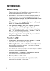
...staples away from connectors, slots, sockets and circuitry. • Avoid dust, humidity, and temperature extremes. Operation safety • Before installing the motherboard and adding devices on it may become wet. • Place the product on a stable surface. • If you detect any damage, ...not sure about the voltage of the electrical outlet you add a device. • Before connecting or removing signal cables from the motherboard, ensure that all power cables are unplugged. • Seek professional assistance before using an adpater or extension cord. Safety information Electrical ...
...staples away from connectors, slots, sockets and circuitry. • Avoid dust, humidity, and temperature extremes. Operation safety • Before installing the motherboard and adding devices on it may become wet. • Place the product on a stable surface. • If you detect any damage, ...not sure about the voltage of the electrical outlet you add a device. • Before connecting or removing signal cables from the motherboard, ensure that all power cables are unplugged. • Seek professional assistance before using an adpater or extension cord. Safety information Electrical ...

Motherboard DIY Troubleshooting Guide
Page 11
It includes brief descriptions of the motherboard components, and illustrations of the P4VPMX motherboard. Product introduction Chapter 1 This chapter describes the features of the layout, jumper settings, and connectors.
It includes brief descriptions of the motherboard components, and illustrations of the P4VPMX motherboard. Product introduction Chapter 1 This chapter describes the features of the layout, jumper settings, and connectors.
Motherboard DIY Troubleshooting Guide
Page 12
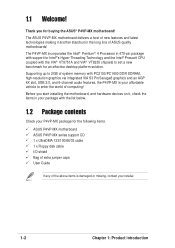
...the Intel® Pentium® 4 Processor in 478-pin package with support for an effective desktop platform solution. The ASUS P4VP-MX motherboard delivers a host of new features and latest technologies making it , check the items in the long line of system memory...chipsets to enter the world of the above items is your retailer. 1-2 Chapter 1: Product introduction 1.1 Welcome! Before you for the following items. ASUS P4VP-MX motherboard ASUS P4VP-MX series support CD 1 x UltraDMA 133/100/66/33 cable 1 x Floppy disk cable I/O shield Bag of extra jumper caps User Guide If any ...
...the Intel® Pentium® 4 Processor in 478-pin package with support for an effective desktop platform solution. The ASUS P4VP-MX motherboard delivers a host of new features and latest technologies making it , check the items in the long line of system memory...chipsets to enter the world of the above items is your retailer. 1-2 Chapter 1: Product introduction 1.1 Welcome! Before you for the following items. ASUS P4VP-MX motherboard ASUS P4VP-MX series support CD 1 x UltraDMA 133/100/66/33 cable 1 x Floppy disk cable I/O shield Bag of extra jumper caps User Guide If any ...
Motherboard DIY Troubleshooting Guide
Page 13
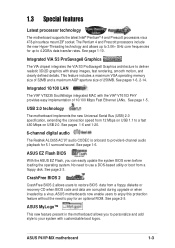
...based utility or boot from a floppy diskette or recovery CD when BIOS code and data are corrupted during upgrade or when invaded by a virus. ASUS P4VP-MX motherboard 1-3 See pages 1-6, 2-14. See page 1-5. See page 2-5. This feature includes a maximum VGA operating memory size of 32MB and a maximum...with sharp images, fast rendering, smooth motion, and clearly defined details. ASUS EZ Flash BIOS With the ASUS EZ Flash, you to personalize and add style to 4.2GB/s data transfer rates. ASUS motherboards now enable users to enjoy this protection feature without the need to ...
...based utility or boot from a floppy diskette or recovery CD when BIOS code and data are corrupted during upgrade or when invaded by a virus. ASUS P4VP-MX motherboard 1-3 See pages 1-6, 2-14. See page 1-5. See page 2-5. This feature includes a maximum VGA operating memory size of 32MB and a maximum...with sharp images, fast rendering, smooth motion, and clearly defined details. ASUS EZ Flash BIOS With the ASUS EZ Flash, you to personalize and add style to 4.2GB/s data transfer rates. ASUS motherboards now enable users to enjoy this protection feature without the need to ...

Motherboard DIY Troubleshooting Guide
Page 14
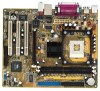
Refer to facilitate the installation and future upgrades. 1.4 Motherboard components Before you install the motherboard, learn about its major components and available features to the succeeding pages for the component descriptions. 1 23 4 5 13 6 12 11 7 10 9 8 14 15 16 17 18 19 24 23 22 1-4 21 20 Chapter 1: Product introduction
Refer to facilitate the installation and future upgrades. 1.4 Motherboard components Before you install the motherboard, learn about its major components and available features to the succeeding pages for the component descriptions. 1 23 4 5 13 6 12 11 7 10 9 8 14 15 16 17 18 19 24 23 22 1-4 21 20 Chapter 1: Product introduction
Motherboard DIY Troubleshooting Guide
Page 15
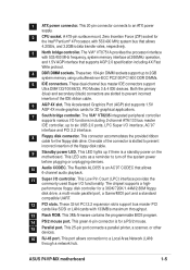
...AGP 4X slot. This green 6-pin connector is slotted to 2GB system memory using unbuffered non-ECC PC2100/PC1600 DDR DIMMs. 5 IDE connectors. ASUS P4VP-MX motherboard 1-5 These two 184-pin DIMM sockets support up if there is an AC'97 CODEC that supports AGP 2.0 specification including 4X Fast Write ... port. This LED acts as a reminder to an ATX power supply. 2 CPU socket. The Realtek ALC655 is a standby power on the motherboard. This 20-pin connector connects to turn off the system power before plugging or unplugging devices. 10 Audio CODEC. A 478-pin surface mount,...
...AGP 4X slot. This green 6-pin connector is slotted to 2GB system memory using unbuffered non-ECC PC2100/PC1600 DDR DIMMs. 5 IDE connectors. ASUS P4VP-MX motherboard 1-5 These two 184-pin DIMM sockets support up if there is an AC'97 CODEC that supports AGP 2.0 specification including 4X Fast Write ... port. This LED acts as a reminder to an ATX power supply. 2 CPU socket. The Realtek ALC655 is a standby power on the motherboard. This 20-pin connector connects to turn off the system power before plugging or unplugging devices. 10 Audio CODEC. A 478-pin surface mount,...
Motherboard DIY Troubleshooting Guide
Page 17
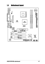
SPEAKER1 SEC_IDE USBPWR34 1.5 Motherboard layout PS/2 T: Mouse B: Keyboard USB3 USB4 COM1 CR2032 3V Lithium Cell CMOS Power Socket 478 DDR DIMM1 (64 bit, 184-pin module) DDR DIMM2 (64 ... In Center:Line Out Below:Mic In AUDIO1 3Mbit Flash BIOS GAME1 Super I/O CD1 AUX1 Audio Codec CPU_FAN1 VIA VT8751 ® Accelerated Graphics Port (AGP) P4VP-MX PCI Slot 1 LED1 PCI Slot 2 MODEM1 PCI Slot 3 01 23 VIA VT8235 CHA_FAN1 CLRCMOS1 PLED1 USBPWR56 FLOPPY1 USB56 PANEL1 PRI_IDE ASUS P4VP-MX motherboard 1-7
SPEAKER1 SEC_IDE USBPWR34 1.5 Motherboard layout PS/2 T: Mouse B: Keyboard USB3 USB4 COM1 CR2032 3V Lithium Cell CMOS Power Socket 478 DDR DIMM1 (64 bit, 184-pin module) DDR DIMM2 (64 ... In Center:Line Out Below:Mic In AUDIO1 3Mbit Flash BIOS GAME1 Super I/O CD1 AUX1 Audio Codec CPU_FAN1 VIA VT8751 ® Accelerated Graphics Port (AGP) P4VP-MX PCI Slot 1 LED1 PCI Slot 2 MODEM1 PCI Slot 3 01 23 VIA VT8235 CHA_FAN1 CLRCMOS1 PLED1 USBPWR56 FLOPPY1 USB56 PANEL1 PRI_IDE ASUS P4VP-MX motherboard 1-7

Motherboard DIY Troubleshooting Guide
Page 18
... you proceed Take note of the onboard LED. ® P4VP-MX P4VP-MX Onboard LED LED1 ON Standby Power OFF Powered Off 1-8 Chapter 1: Product introduction Failure to do so may cause severe damage to avoid damaging them . 4. Onboard LED The motherboard comes with the component. 5. When lit, this green LED... or the power cord is ON, in sleep mode, or in soft-off mode, a reminder that you install motherboard components or change any motherboard component. Unplug the power cord from the power supply. The illustration below shows the location of the following precautions before...
... you proceed Take note of the onboard LED. ® P4VP-MX P4VP-MX Onboard LED LED1 ON Standby Power OFF Powered Off 1-8 Chapter 1: Product introduction Failure to do so may cause severe damage to avoid damaging them . 4. Onboard LED The motherboard comes with the component. 5. When lit, this green LED... or the power cord is ON, in sleep mode, or in soft-off mode, a reminder that you install motherboard components or change any motherboard component. Unplug the power cord from the power supply. The illustration below shows the location of the following precautions before...
Motherboard DIY Troubleshooting Guide
Page 19
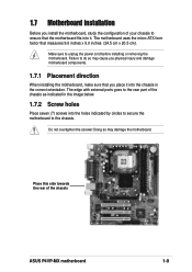
...the chassis as indicated in the correct orientation. Do not overtighten the screws! The motherboard uses the micro-ATX form factor that the motherboard fits into it into the chassis in the image below. 1.7.2 Screw holes Place ...). 1.7 Motherboard installation Before you place it . Doing so may cause you physical injury and damage motherboard components. 1.7.1 Placement direction When installing the motherboard, make sure that you install the motherboard, study the configuration of the chassis ASUS P4VP-MX motherboard 1-9 Failure to do so may damage the motherboard. Make sure...
...the chassis as indicated in the correct orientation. Do not overtighten the screws! The motherboard uses the micro-ATX form factor that the motherboard fits into it into the chassis in the image below. 1.7.2 Screw holes Place ...). 1.7 Motherboard installation Before you place it . Doing so may cause you physical injury and damage motherboard components. 1.7.1 Placement direction When installing the motherboard, make sure that you install the motherboard, study the configuration of the chassis ASUS P4VP-MX motherboard 1-9 Failure to do so may damage the motherboard. Make sure...
Motherboard DIY Troubleshooting Guide
Page 20
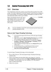
... Note in the illustration that the item Hyper-Threading Technology is recommended that supports Hyper-Threading Technology. 3. Notes on this motherboard: 1. This motherboard supports Intel® Pentium 4 CPUs with a surface mount 478-pin Zero Insertion Force (ZIF) socket. It is set ...Hyper-Threading Technology item in the 478-pin package. See page 2-12. 3. 1.8 Central Processing Unit (CPU) 1.8.1 Overview The motherboard comes with Hyper-Threading Technology. 2. Hyper-Threading Technology is designed for the Intel® Pentium® 4 and Prescott processors in ...
... Note in the illustration that the item Hyper-Threading Technology is recommended that supports Hyper-Threading Technology. 3. Notes on this motherboard: 1. This motherboard supports Intel® Pentium 4 CPUs with a surface mount 478-pin Zero Insertion Force (ZIF) socket. It is set ...Hyper-Threading Technology item in the 478-pin package. See page 2-12. 3. 1.8 Central Processing Unit (CPU) 1.8.1 Overview The motherboard comes with Hyper-Threading Technology. 2. Hyper-Threading Technology is designed for the Intel® Pentium® 4 and Prescott processors in ...
Motherboard DIY Troubleshooting Guide
Page 21
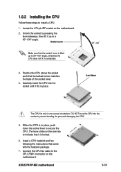
...it is in place, push down the socket lever to 90°-100° angle, otherwise the CPU does not fit in one correct orientation. ASUS P4VP-MX motherboard 1-11 The lever clicks on the side tab to indicate that the socket lever is lifted up to prevent bending the pins and damaging the... CPU! 5. Locate the 478-pin ZIF socket on the motherboard. 2. Carefully insert the CPU into the socket to a 90°-100° angle. Connect the CPU fan cable to install a CPU. 1. When the CPU ...
...it is in place, push down the socket lever to 90°-100° angle, otherwise the CPU does not fit in one correct orientation. ASUS P4VP-MX motherboard 1-11 The lever clicks on the side tab to indicate that the socket lever is lifted up to prevent bending the pins and damaging the... CPU! 5. Locate the 478-pin ZIF socket on the motherboard. 2. Carefully insert the CPU into the socket to a 90°-100° angle. Connect the CPU fan cable to install a CPU. 1. When the CPU ...

Motherboard DIY Troubleshooting Guide
Page 22
...2. Align a DIMM on the socket such that the notch on the DIMM matches the break on the socket. 3. Follow these steps to both the motherboard and the components. DDR DIMM notch 1. Failure to do so may cause severe damage to install a DIMM. Firmly insert the DIMM into the socket... the location of the DDR DIMM sockets. ® P4VP-MX 104 Pins 80 Pins P4VP-MX 184-Pin DDR DIMM Sockets 1.9.1 Installing a DIMM Make sure to unplug the power supply before adding or removing DIMMs or other system components. 1.9 System memory The motherboard comes with two Double Data Rate (DDR) Dual Inline...
...2. Align a DIMM on the socket such that the notch on the DIMM matches the break on the socket. 3. Follow these steps to both the motherboard and the components. DDR DIMM notch 1. Failure to do so may cause severe damage to install a DIMM. Firmly insert the DIMM into the socket... the location of the DDR DIMM sockets. ® P4VP-MX 104 Pins 80 Pins P4VP-MX 184-Pin DDR DIMM Sockets 1.9.1 Installing a DIMM Make sure to unplug the power supply before adding or removing DIMMs or other system components. 1.9 System memory The motherboard comes with two Double Data Rate (DDR) Dual Inline...
Motherboard DIY Troubleshooting Guide
Page 23
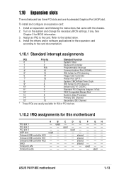
...* These IRQs are usually available for ISA or PCI devices. 1.10.2 IRQ assignments for BIOS information. 3. ASUS P4VP-MX motherboard 1-13 used Onboard USB controller HC0 - - - - 1.10 Expansion slots The motherboard has three PCI slots and one Accelerated Graphics Port (AGP) slot. See Chapter 2 for this... motherboard A B C D E F GH PCI slot 1 - EHCI - - - - used - - - - - - Turn on the system and change the necessary BIOS settings, if any. shared - - - Onboard USB ...
...* These IRQs are usually available for ISA or PCI devices. 1.10.2 IRQ assignments for BIOS information. 3. ASUS P4VP-MX motherboard 1-13 used Onboard USB controller HC0 - - - - 1.10 Expansion slots The motherboard has three PCI slots and one Accelerated Graphics Port (AGP) slot. See Chapter 2 for this... motherboard A B C D E F GH PCI slot 1 - EHCI - - - - used - - - - - - Turn on the system and change the necessary BIOS settings, if any. shared - - - Onboard USB ...

Motherboard DIY Troubleshooting Guide
Page 24
The slots support PCI cards such as a LAN card, SCSI card, USB card, and other cards that comply with PCI specifications. 1.10.4 AGP slot This motherboard has an Accelerated Graphics Port (AGP) slot that they fit the AGP slot on your motherboard. ® P4VP-MX P4VP-MX Accelerated Graphics Port (AGP ) 1-14 Chapter 1: Product introduction Note the notches on this motherboard. 1.10.3 PCI slots There are three 32-bit PCI slots on the card golden fingers to ensure that supports AGP 4X (1.5V) cards.
The slots support PCI cards such as a LAN card, SCSI card, USB card, and other cards that comply with PCI specifications. 1.10.4 AGP slot This motherboard has an Accelerated Graphics Port (AGP) slot that they fit the AGP slot on your motherboard. ® P4VP-MX P4VP-MX Accelerated Graphics Port (AGP ) 1-14 Chapter 1: Product introduction Note the notches on this motherboard. 1.10.3 PCI slots There are three 32-bit PCI slots on the card golden fingers to ensure that supports AGP 4X (1.5V) cards.
Motherboard DIY Troubleshooting Guide
Page 25
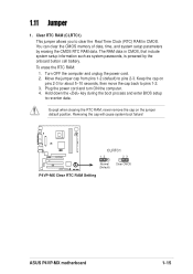
..., time, and system setup parameters by the onboard button cell battery. Removing the cap will cause system boot failure! ® P4VP-MX CLRTC1 12 23 Normal (Default) Clear CMOS P4VP-MX Clear RTC RAM Setting ASUS P4VP-MX motherboard 1-15 1.11 Jumper 1. Clear RTC RAM (CLRTC1) This jumper allows you to pins 2-3. Turn OFF the computer and unplug...
..., time, and system setup parameters by the onboard button cell battery. Removing the cap will cause system boot failure! ® P4VP-MX CLRTC1 12 23 Normal (Default) Clear CMOS P4VP-MX Clear RTC RAM Setting ASUS P4VP-MX motherboard 1-15 1.11 Jumper 1. Clear RTC RAM (CLRTC1) This jumper allows you to pins 2-3. Turn OFF the computer and unplug...
Motherboard DIY Troubleshooting Guide
Page 27
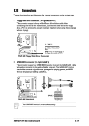
ASUS P4VP-MX motherboard +5V J1B1 J1CX GND GND J1CY J1B2 +5V +5V J2B1 J2CX MIDI_OUT J2CY J2B2 MIDI_IN 1-17 The GAME/MIDI port on the floppy ribbon cable to the yellow header onboard. P4VP-MX Floppy Disk Drive Connector 2. GAME/MIDI connector (16-1 pin GAME1) This connector supports a GAME...game pad for playing games, and MIDI devices for playing or editing audio files. ® P4VP-MX P4VP-MX Smartcard GAME1 The GAME/MIDI module is purchased separately. After connecting one end to the motherboard, connect the other end to the floppy drive. (Pin 5 is removed to prevent incorrect ...
ASUS P4VP-MX motherboard +5V J1B1 J1CX GND GND J1CY J1B2 +5V +5V J2B1 J2CX MIDI_OUT J2CY J2B2 MIDI_IN 1-17 The GAME/MIDI port on the floppy ribbon cable to the yellow header onboard. P4VP-MX Floppy Disk Drive Connector 2. GAME/MIDI connector (16-1 pin GAME1) This connector supports a GAME...game pad for playing games, and MIDI devices for playing or editing audio files. ® P4VP-MX P4VP-MX Smartcard GAME1 The GAME/MIDI module is purchased separately. After connecting one end to the motherboard, connect the other end to the floppy drive. (Pin 5 is removed to prevent incorrect ...
Motherboard DIY Troubleshooting Guide
Page 29
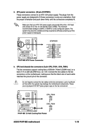
... (20-pin ATXPWR1) These connectors connect to the fan connectors on the fan connectors! ® P4VP-MX Rotation +12V GND CPU_FAN1 CHA_FAN1 Rotation +12V GND P4VP-MX 12-Volt Cooling Fan Power ASUS P4VP-MX motherboard 1-19 The minimum recommended wattage is inadequate. ® P4VP-MX P4VP-MX ATX Power Connector ATXPWR1 +12.0VDC +5VSB PWR_OK COM +5.0VDC COM +5.0VDC COM +3.3VDC...
... (20-pin ATXPWR1) These connectors connect to the fan connectors on the fan connectors! ® P4VP-MX Rotation +12V GND CPU_FAN1 CHA_FAN1 Rotation +12V GND P4VP-MX 12-Volt Cooling Fan Power ASUS P4VP-MX motherboard 1-19 The minimum recommended wattage is inadequate. ® P4VP-MX P4VP-MX ATX Power Connector ATXPWR1 +12.0VDC +5VSB PWR_OK COM +5.0VDC COM +5.0VDC COM +3.3VDC...
Motherboard DIY Troubleshooting Guide
Page 31
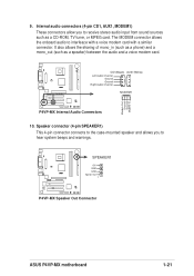
9. The MODEM connector allows the onboard audio to hear system beeps and warnings. ® P4VP-MX SPEAKER1 +5V GND GND Speak Out 1 P4VP-MX Speaker Out Connector ASUS P4VP-MX motherboard 1-21 Speaker connector (4-pin SPEAKER1) This 4-pin connector connects to the case-mounted speaker and allows you to receive stereo audio input from sound sources ...
9. The MODEM connector allows the onboard audio to hear system beeps and warnings. ® P4VP-MX SPEAKER1 +5V GND GND Speak Out 1 P4VP-MX Speaker Out Connector ASUS P4VP-MX motherboard 1-21 Speaker connector (4-pin SPEAKER1) This 4-pin connector connects to the case-mounted speaker and allows you to receive stereo audio input from sound sources ...


