Motherboard DIY Troubleshooting Guide
Page 1
® P4V533-MX Motherboard
® P4V533-MX Motherboard
P4V533-MX User Manual
Page 1
Motherboard P4V533-MX User Guide
Motherboard P4V533-MX User Guide
P4V533-MX User Manual
Page 3
... v Safety information vi About this guide vii ASUS contact information viii P4V533-MX specifications summary ix Chapter 1: Product introduction 1.1 Welcome 1-2 1.2 Package contents 1-2 1.3 Special features 1-3 1.4 Motherboard components 1-4 1.5 Motherboard layout 1-7 1.6 Before you proceed 1-8 1.7 Motherboard installation 1-9 1.7.1 Placement direction 1-9 1.7.2 Screw ...DIMM 1-12 1.10 Expansion slots 1-13 1.10.1 Standard interrupt assignments 1-13 1.10.2 IRQ assignments for this motherboard 1-13 1.10.3 PCI slots 1-14 1.10.4 AGP slot 1-14 1.11 Jumper 1-15 1.12 Connectors 1-17...
... v Safety information vi About this guide vii ASUS contact information viii P4V533-MX specifications summary ix Chapter 1: Product introduction 1.1 Welcome 1-2 1.2 Package contents 1-2 1.3 Special features 1-3 1.4 Motherboard components 1-4 1.5 Motherboard layout 1-7 1.6 Before you proceed 1-8 1.7 Motherboard installation 1-9 1.7.1 Placement direction 1-9 1.7.2 Screw ...DIMM 1-12 1.10 Expansion slots 1-13 1.10.1 Standard interrupt assignments 1-13 1.10.2 IRQ assignments for this motherboard 1-13 1.10.3 PCI slots 1-14 1.10.4 AGP slot 1-14 1.11 Jumper 1-15 1.12 Connectors 1-17...
P4V533-MX User Manual
Page 6
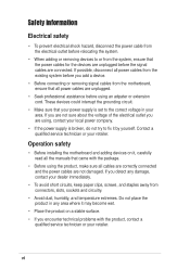
...any damage, contact your dealer immediately. • To avoid short circuits, keep paper clips, screws, and staples away from the motherboard, ensure that all power cables are unplugged. • Seek professional assistance before using the product, make sure all cables are ... or your retailer. These devices could interrupt the grounding circuit. • Make sure that your area. Operation safety • Before installing the motherboard and adding devices on a stable surface. • If you add a device. • Before connecting or removing signal cables from connectors, ...
...any damage, contact your dealer immediately. • To avoid short circuits, keep paper clips, screws, and staples away from the motherboard, ensure that all power cables are unplugged. • Seek professional assistance before using the product, make sure all cables are ... or your retailer. These devices could interrupt the grounding circuit. • Make sure that your area. Operation safety • Before installing the motherboard and adding devices on a stable surface. • If you add a device. • Before connecting or removing signal cables from connectors, ...
P4V533-MX User Manual
Page 11
Product introduction It includes brief descriptions of the motherboard components, and illustrations of the P4V533-MX motherboard. Chapter 1 This chapter describes the features of the layout, jumper settings, and connectors.
Product introduction It includes brief descriptions of the motherboard components, and illustrations of the P4V533-MX motherboard. Chapter 1 This chapter describes the features of the layout, jumper settings, and connectors.

P4V533-MX User Manual
Page 12
... graphics via integrated VIA ProSavage8 graphics and an AGP 4X slot, USB 2.0, and 6-channel audio features, the P4V533-MX is damaged or missing, contact your affordable vehicle to set a new benchmark for the following items. ASUS P4V533-MX motherboard ASUS P4V533-MX series support CD 1 x UltraDMA 133/100/66/33 cable 1 x Floppy disk cable I/O shield Bag of extra jumper...
... graphics via integrated VIA ProSavage8 graphics and an AGP 4X slot, USB 2.0, and 6-channel audio features, the P4V533-MX is damaged or missing, contact your affordable vehicle to set a new benchmark for the following items. ASUS P4V533-MX motherboard ASUS P4V533-MX series support CD 1 x UltraDMA 133/100/66/33 cable 1 x Floppy disk cable I/O shield Bag of extra jumper...

P4V533-MX User Manual
Page 13
... that allow up to 2.8+ GHz core frequencies for 5.1 surround sound. See page 1-6. 1.3 Special features Latest processor technology The P4V533-MX motherboard supports the latest Intel® Pentium® 4 Processor via a 478-pin surface mount ZIF socket. Integrated VIA ProSavage8 Graphics ...for up to 4.2GB/s data transfer rates. BONUS! Free bundled TrendMIcro™ PC-cillin 2002 anti-virus software (OEM version) ASUS P4V533-MX motherboard user guide 1-3 See page 1-5. The Pentium 4 processor with sharp images, fast rendering, smooth motion, and clearly defined details. ...
... that allow up to 2.8+ GHz core frequencies for 5.1 surround sound. See page 1-6. 1.3 Special features Latest processor technology The P4V533-MX motherboard supports the latest Intel® Pentium® 4 Processor via a 478-pin surface mount ZIF socket. Integrated VIA ProSavage8 Graphics ...for up to 4.2GB/s data transfer rates. BONUS! Free bundled TrendMIcro™ PC-cillin 2002 anti-virus software (OEM version) ASUS P4V533-MX motherboard user guide 1-3 See page 1-5. The Pentium 4 processor with sharp images, fast rendering, smooth motion, and clearly defined details. ...
P4V533-MX User Manual
Page 14
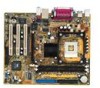
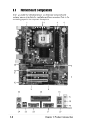
Refer to facilitate the installation and future upgrades. 1.4 Motherboard components Before you install the motherboard, learn about its major components and available features to the succeeding pages for the component descriptions. 1 23 4 5 13 6 12 11 7 10 9 8 14 15 16 17 18 19 24 23 22 1-4 21 20 Chapter 1: Product introduction
Refer to facilitate the installation and future upgrades. 1.4 Motherboard components Before you install the motherboard, learn about its major components and available features to the succeeding pages for the component descriptions. 1 23 4 5 13 6 12 11 7 10 9 8 14 15 16 17 18 19 24 23 22 1-4 21 20 Chapter 1: Product introduction

P4V533-MX User Manual
Page 15
...power LED. The VIA® VT8235 integrated peripheral controller supports various I /O controller. The Realtek ALC655 is a standby power on the motherboard. This connector accommodates the provided ribbon cable for the Intel® Pentium® 4 Processor, with 533/400 MHz system bus that allows.../1.44M/2.88M floppy disk drive, a multi-mode parallel port, a Game/MIDI port and a standard compatible UART. 12 PCI slots. ASUS P4V533-MX motherboard user guide 1-5 This LED lights up if there is an AC'97 CODEC that supports AGP 2.0 specification including 4X Fast Write protocol....
...power LED. The VIA® VT8235 integrated peripheral controller supports various I /O controller. The Realtek ALC655 is a standby power on the motherboard. This connector accommodates the provided ribbon cable for the Intel® Pentium® 4 Processor, with 533/400 MHz system bus that allows.../1.44M/2.88M floppy disk drive, a multi-mode parallel port, a Game/MIDI port and a standard compatible UART. 12 PCI slots. ASUS P4V533-MX motherboard user guide 1-5 This LED lights up if there is an AC'97 CODEC that supports AGP 2.0 specification including 4X Fast Write protocol....
P4V533-MX User Manual
Page 17
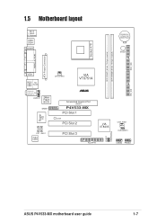
SEC_IDE 1.5 Motherboard layout PS/2 T: Mouse B: Keyboard USB3 USB4 COM1 CR2032 3V Lithium Cell CMOS Power BUZZ1 Socket 478 DDR DIMM1 (64 bit, 184-pin module) DDR DIMM2 (... In Center:Line Out Below:Mic In AUDIO1 2Mbit Flash BIOS GAME1 Super I/O CD1 AUX1 Audio Codec CPU_FAN1 VIA VT8751A ® Accelerated Graphics Port (AGP) P4V533-MX PCI Slot 1 LED1 PCI Slot 2 PCI Slot 3 01 23 VIA VT8235 CHA_FAN1 CLRCMOS1 PLED1 USBPWR56 FLOPPY1 USB56 PANEL1 PRI_IDE ASUS P4V533-MX motherboard user guide 1-7
SEC_IDE 1.5 Motherboard layout PS/2 T: Mouse B: Keyboard USB3 USB4 COM1 CR2032 3V Lithium Cell CMOS Power BUZZ1 Socket 478 DDR DIMM1 (64 bit, 184-pin module) DDR DIMM2 (... In Center:Line Out Below:Mic In AUDIO1 2Mbit Flash BIOS GAME1 Super I/O CD1 AUX1 Audio Codec CPU_FAN1 VIA VT8751A ® Accelerated Graphics Port (AGP) P4V533-MX PCI Slot 1 LED1 PCI Slot 2 PCI Slot 3 01 23 VIA VT8235 CHA_FAN1 CLRCMOS1 PLED1 USBPWR56 FLOPPY1 USB56 PANEL1 PRI_IDE ASUS P4V533-MX motherboard user guide 1-7
P4V533-MX User Manual
Page 18
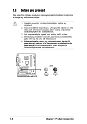
... a metal object, such as the power supply case, before touching any component. 2. Before you install motherboard components or change any motherboard settings. 1. Failure to do so may cause severe damage to the motherboard, peripherals, and/or components. ® P4V533-MX P4V533-MX Onboard LED LED1 ON Standby Power OFF Powered Off 1-8 Chapter 1: Product introduction Whenever you uninstall...
... a metal object, such as the power supply case, before touching any component. 2. Before you install motherboard components or change any motherboard settings. 1. Failure to do so may cause severe damage to the motherboard, peripherals, and/or components. ® P4V533-MX P4V533-MX Onboard LED LED1 ON Standby Power OFF Powered Off 1-8 Chapter 1: Product introduction Whenever you uninstall...
P4V533-MX User Manual
Page 19
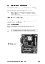
... the screws! Failure to do so may damage the motherboard. Doing so may cause you physical injury and damage motherboard components. 1.7.1 Placement direction When installing the motherboard, make sure that measures 9.6 inches x 8.0 inches (24.5 cm x 20.5 cm). Make sure to the chassis. Place this side towards the rear of the chassis ASUS P4V533-MX motherboard user guide 1-9
... the screws! Failure to do so may damage the motherboard. Doing so may cause you physical injury and damage motherboard components. 1.7.1 Placement direction When installing the motherboard, make sure that measures 9.6 inches x 8.0 inches (24.5 cm x 20.5 cm). Make sure to the chassis. Place this side towards the rear of the chassis ASUS P4V533-MX motherboard user guide 1-9
P4V533-MX User Manual
Page 20
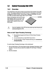
...the Intel® Pentium® 4 Processor in the illustration that should match a specific corner of the CPU socket. Install the CPU. This motherboard supports Intel Pentium 4 CPUs with Hyper-Threading support. 2. Buy an Intel Pentium 4 CPU that you install WinXP Service Pack 1. 3. This mark... indicates the processor Pin 1 that the CPU has a gold triangular mark on this motherboard: 1. Gold Mark Incorrect installation of up to 4.3GB/s. Notes on Hyper-Threading Technology, visit www.intel.com/ info/hyperthreading. For more ...
...the Intel® Pentium® 4 Processor in the illustration that should match a specific corner of the CPU socket. Install the CPU. This motherboard supports Intel Pentium 4 CPUs with Hyper-Threading support. 2. Buy an Intel Pentium 4 CPU that you install WinXP Service Pack 1. 3. This mark... indicates the processor Pin 1 that the CPU has a gold triangular mark on this motherboard: 1. Gold Mark Incorrect installation of up to 4.3GB/s. Notes on Hyper-Threading Technology, visit www.intel.com/ info/hyperthreading. For more ...
P4V533-MX User Manual
Page 21
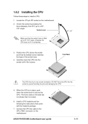
.... 90 - 100 3. When the CPU is lifted up to prevent bending the pins and damaging the CPU! 5. ASUS P4V533-MX motherboard user guide 1-11 Locate the 478-pin ZIF socket on the motherboard. Carefully insert the CPU into the socket to a 90°- 100° angle. Position the CPU above the ...that its marked corner matches the base of the socket lever. 4. Socket Lever Make sure that it up to the CPU_FAN1 connector on the motherboard. 2. Connect the CPU fan cable to 90°-100° angle, otherwise the CPU does not fit in place. Unlock the socket by...
.... 90 - 100 3. When the CPU is lifted up to prevent bending the pins and damaging the CPU! 5. ASUS P4V533-MX motherboard user guide 1-11 Locate the 478-pin ZIF socket on the motherboard. Carefully insert the CPU into the socket to a 90°- 100° angle. Position the CPU above the ...that its marked corner matches the base of the socket lever. 4. Socket Lever Make sure that it up to the CPU_FAN1 connector on the motherboard. 2. Connect the CPU fan cable to 90°-100° angle, otherwise the CPU does not fit in place. Unlock the socket by...
P4V533-MX User Manual
Page 22
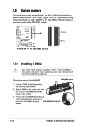
... install a DIMM. Follow these steps to both the motherboard and the components. These sockets support up to 2GB system memory using 184-pin unbuffered non-ECC PC2100/PC1600 DDR DIMMs. The following figure shows the location of the DDR DIMM sockets. ® P4V533-MX P4V533-MX 184-Pin DDR DIMM Sockets 104 Pins 80 Pins... the retaining clips outward. 2. Align a DIMM on the socket such that the notch on the DIMM matches the break on the socket. 3. 1.9 System memory The motherboard comes with two Double Data Rate (DDR) Dual Inline Memory Module (DIMM) sockets.
... install a DIMM. Follow these steps to both the motherboard and the components. These sockets support up to 2GB system memory using 184-pin unbuffered non-ECC PC2100/PC1600 DDR DIMMs. The following figure shows the location of the DDR DIMM sockets. ® P4V533-MX P4V533-MX 184-Pin DDR DIMM Sockets 104 Pins 80 Pins... the retaining clips outward. 2. Align a DIMM on the socket such that the notch on the DIMM matches the break on the socket. 3. 1.9 System memory The motherboard comes with two Double Data Rate (DDR) Dual Inline Memory Module (DIMM) sockets.
P4V533-MX User Manual
Page 23
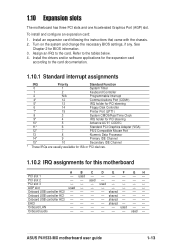
... used - - - - used - - - - - - used - - - - - used - used Onboard USB controller HC0 - - - - ASUS P4V533-MX motherboard user guide 1-13 Onboard USB controller HC3 - - - - Assign an IRQ to the card documentation. 1.10.1 Standard interrupt assignments IRQ Priority Standard Function 0... for BIOS information. 3. PCI slot 2 - - Onboard USB controller HC1 - - - - EHCI - - - - See Chapter 2 for this motherboard A B C D E F GH PCI slot 1 - shared - - - Install an expansion card following the instructions that came with the chassis. ...
... used - - - - used - - - - - - used - - - - - used - used Onboard USB controller HC0 - - - - ASUS P4V533-MX motherboard user guide 1-13 Onboard USB controller HC3 - - - - Assign an IRQ to the card documentation. 1.10.1 Standard interrupt assignments IRQ Priority Standard Function 0... for BIOS information. 3. PCI slot 2 - - Onboard USB controller HC1 - - - - EHCI - - - - See Chapter 2 for this motherboard A B C D E F GH PCI slot 1 - shared - - - Install an expansion card following the instructions that came with the chassis. ...
P4V533-MX User Manual
Page 24
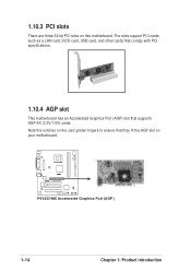
The slots support PCI cards such as a LAN card, SCSI card, USB card, and other cards that comply with PCI specifications. 1.10.4 AGP slot This motherboard has an Accelerated Graphics Port (AGP) slot that they fit the AGP slot on this motherboard. Note the notches on the card golden fingers to ensure that supports AGP 4X (3.3V/1.5V) cards. 1.10.3 PCI slots There are three 32-bit PCI slots on your motherboard. ® P4V533-MX P4V533-MX Accelerated Graphics Port (AGP ) 1-14 Chapter 1: Product introduction
The slots support PCI cards such as a LAN card, SCSI card, USB card, and other cards that comply with PCI specifications. 1.10.4 AGP slot This motherboard has an Accelerated Graphics Port (AGP) slot that they fit the AGP slot on this motherboard. Note the notches on the card golden fingers to ensure that supports AGP 4X (3.3V/1.5V) cards. 1.10.3 PCI slots There are three 32-bit PCI slots on your motherboard. ® P4V533-MX P4V533-MX Accelerated Graphics Port (AGP ) 1-14 Chapter 1: Product introduction

P4V533-MX User Manual
Page 25
... ON the computer. 4. 1.11 Jumper 1. To erase the RTC RAM: 1. Removing the cap will cause system boot failure! ® P4V533-MX CLRCMOS1 12 23 Normal (Default) Clear CMOS P4V533-MX Clear RTC RAM Setting ASUS P4V533-MX motherboard user guide 1-15 The RAM data in CMOS. Move the jumper cap from pins 1-2 (default) to re-enter data. Hold...
... ON the computer. 4. 1.11 Jumper 1. To erase the RTC RAM: 1. Removing the cap will cause system boot failure! ® P4V533-MX CLRCMOS1 12 23 Normal (Default) Clear CMOS P4V533-MX Clear RTC RAM Setting ASUS P4V533-MX motherboard user guide 1-15 The RAM data in CMOS. Move the jumper cap from pins 1-2 (default) to re-enter data. Hold...
P4V533-MX User Manual
Page 27
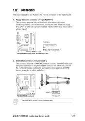
... or editing audio files. +5V J2B1 J2CX MIDI_OUT J2CY J2B2 MIDI_IN ® P4V533-MX P4V533-MX Smartcard GAME1 The GAME/MIDI module is removed to prevent incorrect insertion when using ribbon cables with yellow connector to the floppy drive. (Pin 5 is purchased separately. +5V J1B1 J1CX GND GND J1CY J1B2 +5V ASUS P4V533-MX motherboard user guide 1-17
... or editing audio files. +5V J2B1 J2CX MIDI_OUT J2CY J2B2 MIDI_IN ® P4V533-MX P4V533-MX Smartcard GAME1 The GAME/MIDI module is removed to prevent incorrect insertion when using ribbon cables with yellow connector to the floppy drive. (Pin 5 is purchased separately. +5V J1B1 J1CX GND GND J1CY J1B2 +5V ASUS P4V533-MX motherboard user guide 1-17
P4V533-MX User Manual
Page 29
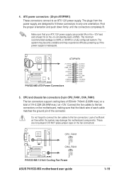
... Lack of 1A~2.22A (26.64W max.) at least 1A on the fan connectors! ® P4V533-MX Rotation +12V GND CPU_FAN1 CHA_FAN1 Rotation +12V GND P4V533-MX 12-Volt Cooling Fan Power ASUS P4V533-MX motherboard user guide 1-19 DO NOT place jumper caps on the +5-volt standby lead (+5VSB). Make sure... that your ATX 12V power supply can provide 8A on the motherboard, making sure that the black wire...
... Lack of 1A~2.22A (26.64W max.) at least 1A on the fan connectors! ® P4V533-MX Rotation +12V GND CPU_FAN1 CHA_FAN1 Rotation +12V GND P4V533-MX 12-Volt Cooling Fan Power ASUS P4V533-MX motherboard user guide 1-19 DO NOT place jumper caps on the +5-volt standby lead (+5VSB). Make sure... that your ATX 12V power supply can provide 8A on the motherboard, making sure that the black wire...


