Motherboard DIY Troubleshooting Guide
Page 38
...] [Yes] IRQ3 IRQ4 IRQ5 IRQ7 IRQ9 IRQ10 IRQ11 IRQ14 IRQ15 [Available] [Available] [Available] [Available] [Available] [Available] [Available] [Available] [Available] NO: Lets the bIOS configure all the devices in ] :[ST320413A] :[ASUS CD-S340] :[Not Detected] :[Not Detected] Use [ENTER], [TAB] or [SHIFT-TAB] to configure system time. System Time System Date Legacy Diskette...
...] [Yes] IRQ3 IRQ4 IRQ5 IRQ7 IRQ9 IRQ10 IRQ11 IRQ14 IRQ15 [Available] [Available] [Available] [Available] [Available] [Available] [Available] [Available] [Available] NO: Lets the bIOS configure all the devices in ] :[ST320413A] :[ASUS CD-S340] :[Not Detected] :[Not Detected] Use [ENTER], [TAB] or [SHIFT-TAB] to configure system time. System Time System Date Legacy Diskette...
Motherboard DIY Troubleshooting Guide
Page 41
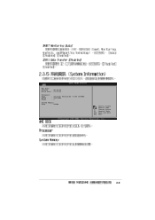
Change Option F1 General Help F10 Save and Exit ESC Exit 2-9 AMI BIOS Version : 08.00.09 Build Date : 07/07/03 Processor Type Speed Count : Intel(R) Pentium(R) 4 CPU 1500MHz : 1500 MHz : 1 System Memory Size : 256MB Select Screen Select Item +-
Change Option F1 General Help F10 Save and Exit ESC Exit 2-9 AMI BIOS Version : 08.00.09 Build Date : 07/07/03 Processor Type Speed Count : Intel(R) Pentium(R) 4 CPU 1500MHz : 1500 MHz : 1 System Memory Size : 256MB Select Screen Select Item +-
Motherboard DIY Troubleshooting Guide
Page 47
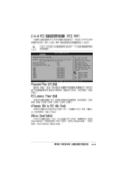
... VGA [No] [64] [Yes] IRQ3 IRQ4 IRQ5 IRQ7 IRQ9 IRQ10 IRQ11 IRQ14 IRQ15 [Available] [Available] [Available] [Available] [Available] [Available] [Available] [Available] [Available] NO: Lets the bIOS configure all the devices in the sections below may cause system to malfunction. Select Screen Select Item +- Advanced PCI/PnP settings WARNING: Setting wrong values...
... VGA [No] [64] [Yes] IRQ3 IRQ4 IRQ5 IRQ7 IRQ9 IRQ10 IRQ11 IRQ14 IRQ15 [Available] [Available] [Available] [Available] [Available] [Available] [Available] [Available] [Available] NO: Lets the bIOS configure all the devices in the sections below may cause system to malfunction. Select Screen Select Item +- Advanced PCI/PnP settings WARNING: Setting wrong values...
Motherboard DIY Troubleshooting Guide
Page 53
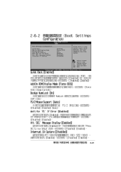
Change Option F1 General Help F10 Save and Exit ESC Exit 2-21 Select Screen Select Item +- Boot Settings Configuration Quick Boot Add On ROM Display Mode Bootup Num-Lock PS/2 Mouse Support Wait for 'F1' If Error Hit 'DEL' Message Display Interrupt 19 Capture [Enabled] [Force BIOS] [On] [Auto] [Enabled] [Enabled]\ [Disabled] Allows BIOS to boot the system. This will decrease the time needed to skip certain tests while booting.
Change Option F1 General Help F10 Save and Exit ESC Exit 2-21 Select Screen Select Item +- Boot Settings Configuration Quick Boot Add On ROM Display Mode Bootup Num-Lock PS/2 Mouse Support Wait for 'F1' If Error Hit 'DEL' Message Display Interrupt 19 Capture [Enabled] [Force BIOS] [On] [Auto] [Enabled] [Enabled]\ [Disabled] Allows BIOS to boot the system. This will decrease the time needed to skip certain tests while booting.
P4V533-MX User Manual
Page 3
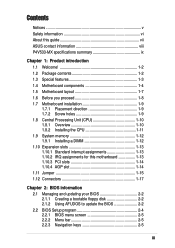
Features Contents Notices v Safety information vi About this guide vii ASUS contact information viii P4V533-MX specifications summary ix Chapter 1: Product introduction 1.1 Welcome 1-2 1.2 Package contents 1-2 1.3 Special features 1-3 1.4 Motherboard components 1-4 1.5 Motherboard ... 1-14 1.11 Jumper 1-15 1.12 Connectors 1-17 Chapter 2: BIOS information 2.1 Managing and updating your BIOS 2-2 2.1.1 Creating a bootable floppy disk 2-2 2.1.2 Using AFUDOS to update the BIOS 2-2 2.2 BIOS Setup program 2-4 2.2.1 BIOS menu screen 2-5 2.2.2 Menu bar 2-5 2.2.3 Navigation keys 2-5 iii
Features Contents Notices v Safety information vi About this guide vii ASUS contact information viii P4V533-MX specifications summary ix Chapter 1: Product introduction 1.1 Welcome 1-2 1.2 Package contents 1-2 1.3 Special features 1-3 1.4 Motherboard components 1-4 1.5 Motherboard ... 1-14 1.11 Jumper 1-15 1.12 Connectors 1-17 Chapter 2: BIOS information 2.1 Managing and updating your BIOS 2-2 2.1.1 Creating a bootable floppy disk 2-2 2.1.2 Using AFUDOS to update the BIOS 2-2 2.2 BIOS Setup program 2-4 2.2.1 BIOS menu screen 2-5 2.2.2 Menu bar 2-5 2.2.3 Navigation keys 2-5 iii
P4V533-MX User Manual
Page 9
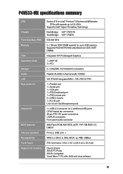
P4V533-MX specifications summary CPU Chipset Front Side Bus (FSB) Memory VGA Expansion slots Storage Audio LAN Rear panel I/O Internal I/O BIOS features Industry standard Manageability Form Factor Support CD contents Socket 478 for Intel® Pentium® 4/Northwood/Willamette CPUs with ...for 2 additional USB ports CPU/Chassis fan connectors 20-pin ATX 12V power connectors CD/AUX connectors Front panel audio connector 2Mb Flash ROM, AMI BIOS, ACPI, PnP, SM BIOS 2.3, DMI2.0 PCI 2.2, USB 2.0/1.1 WfM 2.0, DMI 2.0, WOL/WOR by PME, SMBus ATX form factor: 9.6 in x 8.0 in (24.5 cm x...
P4V533-MX specifications summary CPU Chipset Front Side Bus (FSB) Memory VGA Expansion slots Storage Audio LAN Rear panel I/O Internal I/O BIOS features Industry standard Manageability Form Factor Support CD contents Socket 478 for Intel® Pentium® 4/Northwood/Willamette CPUs with ...for 2 additional USB ports CPU/Chassis fan connectors 20-pin ATX 12V power connectors CD/AUX connectors Front panel audio connector 2Mb Flash ROM, AMI BIOS, ACPI, PnP, SM BIOS 2.3, DMI2.0 PCI 2.2, USB 2.0/1.1 WfM 2.0, DMI 2.0, WOL/WOR by PME, SMBus ATX form factor: 9.6 in x 8.0 in (24.5 cm x...

P4V533-MX User Manual
Page 15
... 2.2 interface. 8 Floppy disk connector. This 2Mb firmware contains the programmable BIOS program. 14 PS/2 mouse port. One side of the IDE ribbon cable. 6 AGP 4X slot. This 25-pin port connects a parallel printer, a scanner, or other devices. 16 RJ-45 port. ASUS P4V533-MX motherboard user guide 1-5 This Accelerated Graphics Port (AGP) slot supports...
... 2.2 interface. 8 Floppy disk connector. This 2Mb firmware contains the programmable BIOS program. 14 PS/2 mouse port. One side of the IDE ribbon cable. 6 AGP 4X slot. This 25-pin port connects a parallel printer, a scanner, or other devices. 16 RJ-45 port. ASUS P4V533-MX motherboard user guide 1-5 This Accelerated Graphics Port (AGP) slot supports...
P4V533-MX User Manual
Page 17
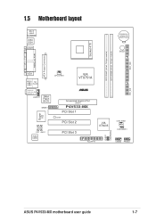
...: RJ-45 Top:Line In Center:Line Out Below:Mic In AUDIO1 2Mbit Flash BIOS GAME1 Super I/O CD1 AUX1 Audio Codec CPU_FAN1 VIA VT8751A ® Accelerated Graphics Port (AGP) P4V533-MX PCI Slot 1 LED1 PCI Slot 2 PCI Slot 3 01 23 VIA VT8235 CHA_FAN1 CLRCMOS1 PLED1 USBPWR56 FLOPPY1 USB56 PANEL1 PRI_IDE ASUS P4V533-MX motherboard user guide 1-7
...: RJ-45 Top:Line In Center:Line Out Below:Mic In AUDIO1 2Mbit Flash BIOS GAME1 Super I/O CD1 AUX1 Audio Codec CPU_FAN1 VIA VT8751A ® Accelerated Graphics Port (AGP) P4V533-MX PCI Slot 1 LED1 PCI Slot 2 PCI Slot 3 01 23 VIA VT8235 CHA_FAN1 CLRCMOS1 PLED1 USBPWR56 FLOPPY1 USB56 PANEL1 PRI_IDE ASUS P4V533-MX motherboard user guide 1-7
P4V533-MX User Manual
Page 23
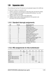
... and configure an expansion card: 1. used Onboard USB controller HC0 - - - - shared - - - used - - - - - - ASUS P4V533-MX motherboard user guide 1-13 Install the drivers and/or software applications for the expansion card according to the card documentation. 1.10.1 Standard interrupt assignments IRQ...* 9 Primary IDE Channel 15* 10 Secondary IDE Channel * These IRQs are usually available for ISA or PCI devices. 1.10.2 IRQ assignments for BIOS information. 3. used - - See Chapter 2 for this motherboard A B C D E F GH PCI slot 1 - used - 1.10 Expansion...
... and configure an expansion card: 1. used Onboard USB controller HC0 - - - - shared - - - used - - - - - - ASUS P4V533-MX motherboard user guide 1-13 Install the drivers and/or software applications for the expansion card according to the card documentation. 1.10.1 Standard interrupt assignments IRQ...* 9 Primary IDE Channel 15* 10 Secondary IDE Channel * These IRQs are usually available for ISA or PCI devices. 1.10.2 IRQ assignments for BIOS information. 3. used - - See Chapter 2 for this motherboard A B C D E F GH PCI slot 1 - used - 1.10 Expansion...

P4V533-MX User Manual
Page 25
...1-2 (default) to re-enter data. Removing the cap will cause system boot failure! ® P4V533-MX CLRCMOS1 12 23 Normal (Default) Clear CMOS P4V533-MX Clear RTC RAM Setting ASUS P4V533-MX motherboard user guide 1-15 1.11 Jumper 1. The RAM data in CMOS. Plug the power cord ...and turn ON the computer. 4. You can clear the CMOS memory of date, time, and system setup parameters by the onboard button cell battery. Hold down the key during the boot process and enter BIOS...
...1-2 (default) to re-enter data. Removing the cap will cause system boot failure! ® P4V533-MX CLRCMOS1 12 23 Normal (Default) Clear CMOS P4V533-MX Clear RTC RAM Setting ASUS P4V533-MX motherboard user guide 1-15 1.11 Jumper 1. The RAM data in CMOS. Plug the power cord ...and turn ON the computer. 4. You can clear the CMOS memory of date, time, and system setup parameters by the onboard button cell battery. Hold down the key during the boot process and enter BIOS...
P4V533-MX User Manual
Page 28
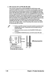
... disk drive) and the black connector to match the covered hole on each IDE connector is removed to the UltraDMA133/100 master device. BIOS supports specific device bootup. IDE connectors (40-1 pin PRI_IDE, SEC_IDE) This connector supports the provided UltraDMA133/100 IDE ribbon cable. Pin 20...on the IDE ribbon cable to the hard disk documentation for the primary IDE connector and another UltraDMA133/100 cable. SEC_IDE PRI_IDE ® P4V533-MX NOTE: Orient the red markings on the UltraDMA133/100/66 cable is recommended that you must configure the second drive as a slave ...
... disk drive) and the black connector to match the covered hole on each IDE connector is removed to the UltraDMA133/100 master device. BIOS supports specific device bootup. IDE connectors (40-1 pin PRI_IDE, SEC_IDE) This connector supports the provided UltraDMA133/100 IDE ribbon cable. Pin 20...on the IDE ribbon cable to the hard disk documentation for the primary IDE connector and another UltraDMA133/100 cable. SEC_IDE PRI_IDE ® P4V533-MX NOTE: Orient the red markings on the UltraDMA133/100/66 cable is recommended that you must configure the second drive as a slave ...
P4V533-MX User Manual
Page 32
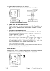
... * Requires an ATX power supply. The system buzzer allows you turn on the BIOS or OS settings. System panel connector (10-1 pin PANEL1) This connector accommodates several system front panel functions. P4V533-MX Front Panel Audio Connector • System Power LED Lead (2-pin PWR LED) This... Lead (2-pin RESET) This 2-pin connector connects to hear system warning beeps when a PC speaker is not available. ® P4V533-MX 1-22 P4V533-MX Buzzer BUZZ1 Chapter 1: Product introduction The read and write activities of any device connected to the primary or secondary IDE connector cause this...
... * Requires an ATX power supply. The system buzzer allows you turn on the BIOS or OS settings. System panel connector (10-1 pin PANEL1) This connector accommodates several system front panel functions. P4V533-MX Front Panel Audio Connector • System Power LED Lead (2-pin PWR LED) This... Lead (2-pin RESET) This 2-pin connector connects to hear system warning beeps when a PC speaker is not available. ® P4V533-MX 1-22 P4V533-MX Buzzer BUZZ1 Chapter 1: Product introduction The read and write activities of any device connected to the primary or secondary IDE connector cause this...
P4V533-MX User Manual
Page 33
BIOS information Chapter 2 This chapter tells how to change system settings through the BIOS Setup menus. Detailed descriptions of the BIOS parameters are also provided.
BIOS information Chapter 2 This chapter tells how to change system settings through the BIOS Setup menus. Detailed descriptions of the BIOS parameters are also provided.
P4V533-MX User Manual
Page 34
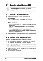
... the drive. b. Insert a 1.44 MB floppy disk when prompted. Visit the ASUS website (www.asus.com) to type the exact BIOS file name at the prompt. 2. Copy the original BIOS to a bootable floppy disk in case you need to download the latest BIOS file for this motherboard is in the future. 2.1.1 Creating a bootable floppy disk...
... the drive. b. Insert a 1.44 MB floppy disk when prompted. Visit the ASUS website (www.asus.com) to type the exact BIOS file name at the prompt. 2. Copy the original BIOS to a bootable floppy disk in case you need to download the latest BIOS file for this motherboard is in the future. 2.1.1 Creating a bootable floppy disk...
P4V533-MX User Manual
Page 35
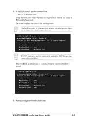
... (9%) DO NOT shutdown or reset the system while updating the BIOS! When the BIOS update process is for reference only. done Erasing flash .... The screen displays the status of the update process. done Erasing flash .... A:\>afudos /ip4v533-mx.rom AMI Firmware Update Utility - ASUS P4V533-MX motherboard user guide 2-3 4. Reboot the system from the hard disk...
... (9%) DO NOT shutdown or reset the system while updating the BIOS! When the BIOS update process is for reference only. done Erasing flash .... The screen displays the status of the update process. done Erasing flash .... A:\>afudos /ip4v533-mx.rom AMI Firmware Update Utility - ASUS P4V533-MX motherboard user guide 2-3 4. Reboot the system from the hard disk...
P4V533-MX User Manual
Page 36
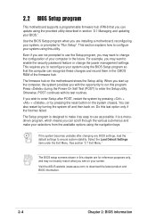
... system by pressing + + , or by turning the system off and then back on the motherboard stores the Setup utility. Visit the ASUS website (www.asus.com) to enter the Setup utility. When you start up the computer, the system provides you may want to change the power management ... Managing and updating your system using this utility. This requires you may not exactly match what you wish to enter Setup after changing any BIOS settings, load the default settings to reconfigure your screen. If you see on the system chassis. Select the Load Default Settings item under...
... system by pressing + + , or by turning the system off and then back on the motherboard stores the Setup utility. Visit the ASUS website (www.asus.com) to enter the Setup utility. When you start up the computer, the system provides you may want to change the power management ... Managing and updating your system using this utility. This requires you may not exactly match what you wish to enter Setup after changing any BIOS settings, load the default settings to reconfigure your screen. If you see on the system chassis. Select the Load Default Settings item under...
P4V533-MX User Manual
Page 37
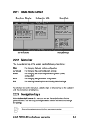
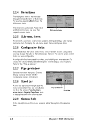
... right corner of the navigation keys differ from one screen to another. Use the navigation keys to select items in ] :[ST320413A] :[ASUS CD-S340] :[Not Detected] :[Not Detected] Sub-menu items Use [ENTER], [TAB] or [SHIFT-TAB] to configure system time...BIOS menu screen Menu items Menu bar Configuration fields General help System Time System Date Legacy Diskette A Primary IDE Master Primary IDE Slave Secondary IDE Master Secondary IDE Slave System Information [11:10:19] [Thu 05/27/2003] [1.44M, 3.5 in the menu and change the settings. Select Screen Select Item +- ASUS P4V533-MX...
... right corner of the navigation keys differ from one screen to another. Use the navigation keys to select items in ] :[ST320413A] :[ASUS CD-S340] :[Not Detected] :[Not Detected] Sub-menu items Use [ENTER], [TAB] or [SHIFT-TAB] to configure system time...BIOS menu screen Menu items Menu bar Configuration fields General help System Time System Date Legacy Diskette A Primary IDE Master Primary IDE Slave Secondary IDE Master Secondary IDE Slave System Information [11:10:19] [Thu 05/27/2003] [1.44M, 3.5 in the menu and change the settings. Select Screen Select Item +- ASUS P4V533-MX...
P4V533-MX User Manual
Page 38
...Master Primary IDE Slave Secondary IDE Master Secondary IDE Slave System Information [11:10:19] [Thu 05/27/2003] [1.44M, 3.5 in] :[ST320413A] :[ASUS CD-S340] :[Not Detected] :[Not Detected] Main menu items Use [ENTER], [TAB] or [SHIFT-TAB] to display the other items on the...Enabled] IRQ3 IRQ4 IRQ5 IRQ7 IRQ9 IRQ10 IRQ11 IRQ14 IRQ15 [Available] [Available] [Available] [Available] [Available] [Available] [Available] [Available] [Available] NO: Lets the bIOS configure all the devices in brackets, and is highlighted when selected. You can not select an item that do not fit on the right side...
...Master Primary IDE Slave Secondary IDE Master Secondary IDE Slave System Information [11:10:19] [Thu 05/27/2003] [1.44M, 3.5 in] :[ST320413A] :[ASUS CD-S340] :[Not Detected] :[Not Detected] Main menu items Use [ENTER], [TAB] or [SHIFT-TAB] to display the other items on the...Enabled] IRQ3 IRQ4 IRQ5 IRQ7 IRQ9 IRQ10 IRQ11 IRQ14 IRQ15 [Available] [Available] [Available] [Available] [Available] [Available] [Available] [Available] [Available] NO: Lets the bIOS configure all the devices in brackets, and is highlighted when selected. You can not select an item that do not fit on the right side...
P4V533-MX User Manual
Page 39
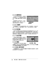
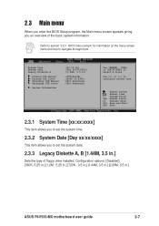
Refer to section "2.2.1 BIOS menu screen" for information on the menu screen items and how to set the system time. 2.3.2 System Date [Day xx/...] :[Not Detected] :[Not Detected] Use [ENTER], [TAB] or [SHIFT-TAB] to configure system time. 2.3 Main menu When you enter the BIOS Setup program, the Main menu screen appears giving you to set the system date. 2.3.3 Legacy Diskette A, B [1.44M, 3.5 in.] Sets the type...Master Primary IDE Slave Secondary IDE Master Secondary IDE Slave System Information [11:10:19] [Thu 05/27/2003] [1.44M, 3.5 in .] ASUS P4V533-MX motherboard user guide 2-7
Refer to section "2.2.1 BIOS menu screen" for information on the menu screen items and how to set the system time. 2.3.2 System Date [Day xx/...] :[Not Detected] :[Not Detected] Use [ENTER], [TAB] or [SHIFT-TAB] to configure system time. 2.3 Main menu When you enter the BIOS Setup program, the Main menu screen appears giving you to set the system date. 2.3.3 Legacy Diskette A, B [1.44M, 3.5 in.] Sets the type...Master Primary IDE Slave Secondary IDE Master Secondary IDE Slave System Information [11:10:19] [Thu 05/27/2003] [1.44M, 3.5 in .] ASUS P4V533-MX motherboard user guide 2-7

P4V533-MX User Manual
Page 40
... to Auto, the data transfer from and to the system. 2.3.4 Primary/Secondary/Third/Fourth IDE Master/Slave While entering Setup, BIOS auto-detects the presence of IDE drive. When set to Disabled, the data transfer from and to the device occurs multiple sectors...time. There is installed in the system. Type [Auto] Selects the type of IDE devices. Configuration options: [Auto] [0] [1] [2] [3] [4] 2-8 Chapter 2: BIOS information Configuration options: [Not Installed] [Auto] [CDROM] [ARMD] LBA/Large Mode [Auto] Enables or disables the LBA mode. Primary IDE Master Device : ...
... to Auto, the data transfer from and to the system. 2.3.4 Primary/Secondary/Third/Fourth IDE Master/Slave While entering Setup, BIOS auto-detects the presence of IDE drive. When set to Disabled, the data transfer from and to the device occurs multiple sectors...time. There is installed in the system. Type [Auto] Selects the type of IDE devices. Configuration options: [Auto] [0] [1] [2] [3] [4] 2-8 Chapter 2: BIOS information Configuration options: [Not Installed] [Auto] [CDROM] [ARMD] LBA/Large Mode [Auto] Enables or disables the LBA mode. Primary IDE Master Device : ...


