
Motherboard DIY Troubleshooting Guide
Page 3
... vii Conventions used in this guide vii Typography vii P4GE-MX specifications summary viii Chapter 1: Product introduction 1.1 Welcome 1-2 1.2 Package contents 1-2 1.3 Special features 1-3 1.3.1 Product Highlights 1-3 1.3.2 Unique ASUS features 1-4 1.4 Before you proceed 1-5 1.5 Motherboard overview 1-6 1.5.1 Motherboard layout 1-6 1.5.2 Placement direction 1-7 1.5.3 Screw holes 1-7 1.6 Central Processing Unit (CPU 1-8 1.6.1 Overview 1-8 1.6.2 Installing the CPU 1-9 1.7 System memory 1-10 1.7.1 DIMM sockets location 1-10 1.7.2 Installing a DIMM 1-10...
... vii Conventions used in this guide vii Typography vii P4GE-MX specifications summary viii Chapter 1: Product introduction 1.1 Welcome 1-2 1.2 Package contents 1-2 1.3 Special features 1-3 1.3.1 Product Highlights 1-3 1.3.2 Unique ASUS features 1-4 1.4 Before you proceed 1-5 1.5 Motherboard overview 1-6 1.5.1 Motherboard layout 1-6 1.5.2 Placement direction 1-7 1.5.3 Screw holes 1-7 1.6 Central Processing Unit (CPU 1-8 1.6.1 Overview 1-8 1.6.2 Installing the CPU 1-9 1.7 System memory 1-10 1.7.1 DIMM sockets location 1-10 1.7.2 Installing a DIMM 1-10...
Motherboard DIY Troubleshooting Guide
Page 12
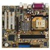
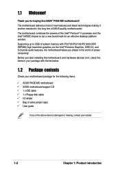
... below. 1.2 Package contents Check your motherboard package for the following items. ASUS P4GE-MX motherboard ASUS motherboard support CD 1 x IDE cable 1 x Floppy disk cable I/O shield Bag of extra jumper caps User guide If any of the Intel® Pentium® 4 processor and the Intel® 845GE chipset to 2GB of system memory with PC2700/PC2100/PC1600 DDR SDRAM...
... below. 1.2 Package contents Check your motherboard package for the following items. ASUS P4GE-MX motherboard ASUS motherboard support CD 1 x IDE cable 1 x Floppy disk cable I/O shield Bag of extra jumper caps User guide If any of the Intel® Pentium® 4 processor and the Intel® 845GE chipset to 2GB of system memory with PC2700/PC2100/PC1600 DDR SDRAM...

Motherboard DIY Troubleshooting Guide
Page 16
1.5 Motherboard overview 1.5.1 Motherboard layout 21.9cm (8.6in) PS/2KBMS T: Mouse B: Keyboard COM1 Socket 478 CPU_FAN Super I/O ATX Power Connector FLOPPY1 DDR DIMM1 (64/72 bit, 184-pin module) ... IDE USB12 Bottom: Top: USB34 RJ-45 USBPWR_34 ATX12V1 Top:Line In Center:Line Out Below:Mic In Intel 82845GE Memory Controller Hub FP_AUDIO Accelerated Graphics Port (AGP) R RTL8100C PCI1 P4GE-MX PCI2 Intel 82801DB ICH4 3Mbit Firmware Hub Audio Codec SPDIF_OUT CD PCI3 CHA_FAN AUX SB_PWR COM2 USBPWR_56 USB56 GAME1 CR2032 3V...
1.5 Motherboard overview 1.5.1 Motherboard layout 21.9cm (8.6in) PS/2KBMS T: Mouse B: Keyboard COM1 Socket 478 CPU_FAN Super I/O ATX Power Connector FLOPPY1 DDR DIMM1 (64/72 bit, 184-pin module) ... IDE USB12 Bottom: Top: USB34 RJ-45 USBPWR_34 ATX12V1 Top:Line In Center:Line Out Below:Mic In Intel 82845GE Memory Controller Hub FP_AUDIO Accelerated Graphics Port (AGP) R RTL8100C PCI1 P4GE-MX PCI2 Intel 82801DB ICH4 3Mbit Firmware Hub Audio Codec SPDIF_OUT CD PCI3 CHA_FAN AUX SB_PWR COM2 USBPWR_56 USB56 GAME1 CR2032 3V...

Motherboard DIY Troubleshooting Guide
Page 20
...DIMM matches the break on the socket. 3. 1.7 System memory 1.7.1 DIMM sockets location You can install 64MB, 256MB, 512MB, and 1GB DDR DIMMs into the DIMM sockets of the DDR DIMM sockets. 80 Pins ® P4GE-MX 104 Pins P4GE-MX 184-Pin DDR DIMM Sockets Make sure to unplug the ...power supply before adding or removing DIMMs or other system components. The following figure illustrates the location of this motherboard. Unlock a DIMM socket by pressing the retaining ...
...DIMM matches the break on the socket. 3. 1.7 System memory 1.7.1 DIMM sockets location You can install 64MB, 256MB, 512MB, and 1GB DDR DIMMs into the DIMM sockets of the DDR DIMM sockets. 80 Pins ® P4GE-MX 104 Pins P4GE-MX 184-Pin DDR DIMM Sockets Make sure to unplug the ...power supply before adding or removing DIMMs or other system components. The following figure illustrates the location of this motherboard. Unlock a DIMM socket by pressing the retaining ...

Motherboard DIY Troubleshooting Guide
Page 23
... RTC RAM CLRTC 12 23 Clear CMOS Normal (Default) You do not need to clear the RTC when the system hangs due to pins 1-2. ASUS P4GE-MX motherboard 1-13 Plug the power cord and turn ON the computer. 4. For system failure due to its previous values. Shut down the key during the boot ... can automatically reset parameter settings to overclocking, use the C.P.R. (CPU Parameter Recall) feature. Hold down and reboot the system so BIOS can clear the CMOS memory of date, time, and system setup parameters by the onboard button cell battery.
... RTC RAM CLRTC 12 23 Clear CMOS Normal (Default) You do not need to clear the RTC when the system hangs due to pins 1-2. ASUS P4GE-MX motherboard 1-13 Plug the power cord and turn ON the computer. 4. For system failure due to its previous values. Shut down the key during the boot ... can automatically reset parameter settings to overclocking, use the C.P.R. (CPU Parameter Recall) feature. Hold down and reboot the system so BIOS can clear the CMOS memory of date, time, and system setup parameters by the onboard button cell battery.
Motherboard DIY Troubleshooting Guide
Page 35
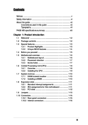
... using the built-in the floppy disk to the bootable floppy disk you created earlier. 2. Save only the updated BIOS file in Flash Memory Writer utility or using this utility. Insert a 1.44 MB floppy disk into the floppy drive. 3. Select the 3 1/2 Floppy Drive ...BIOS file into the floppy disk drive. AWDFLASH checks the new BIOS file from the format options field, then click Start. 2. ASUS P4GE-MX motherboard 2-3 Click File from the ASUS website (www.asus.com). Windows® XP environment a. d. c. e. Reboot the computer. 4. Rename the file to *.BIN and save it ...
... using the built-in the floppy disk to the bootable floppy disk you created earlier. 2. Save only the updated BIOS file in Flash Memory Writer utility or using this utility. Insert a 1.44 MB floppy disk into the floppy drive. 3. Select the 3 1/2 Floppy Drive ...BIOS file into the floppy disk drive. AWDFLASH checks the new BIOS file from the format options field, then click Start. 2. ASUS P4GE-MX motherboard 2-3 Click File from the ASUS website (www.asus.com). Windows® XP environment a. d. c. e. Reboot the computer. 4. Rename the file to *.BIN and save it ...
P4GE-MX User Manual E1722 English Edition
Page 3
... vii Conventions used in this guide vii Typography vii P4GE-MX specifications summary viii Chapter 1: Product introduction 1.1 Welcome 1-2 1.2 Package contents 1-2 1.3 Special features 1-3 1.3.1 Product Highlights 1-3 1.3.2 Unique ASUS features 1-4 1.4 Before you proceed 1-5 1.5 Motherboard overview 1-6 1.5.1 Motherboard layout 1-6 1.5.2 Placement direction 1-7 1.5.3 Screw holes 1-7 1.6 Central Processing Unit (CPU 1-8 1.6.1 Overview 1-8 1.6.2 Installing the CPU 1-9 1.7 System memory 1-10 1.7.1 DIMM sockets location 1-10 1.7.2 Installing a DIMM 1-10...
... vii Conventions used in this guide vii Typography vii P4GE-MX specifications summary viii Chapter 1: Product introduction 1.1 Welcome 1-2 1.2 Package contents 1-2 1.3 Special features 1-3 1.3.1 Product Highlights 1-3 1.3.2 Unique ASUS features 1-4 1.4 Before you proceed 1-5 1.5 Motherboard overview 1-6 1.5.1 Motherboard layout 1-6 1.5.2 Placement direction 1-7 1.5.3 Screw holes 1-7 1.6 Central Processing Unit (CPU 1-8 1.6.1 Overview 1-8 1.6.2 Installing the CPU 1-9 1.7 System memory 1-10 1.7.1 DIMM sockets location 1-10 1.7.2 Installing a DIMM 1-10...

P4GE-MX User Manual E1722 English Edition
Page 12
... you ahead in your package with the list below. 1.2 Package contents Check your motherboard package for the following items. ASUS P4GE-MX motherboard ASUS motherboard support CD 1 x IDE cable 1 x Floppy disk cable I/O shield Bag of extra jumper caps User guide If any of system memory with PC2700/PC2100/PC1600 DDR SDRAM, high-resolution graphics via the Intel®...
... you ahead in your package with the list below. 1.2 Package contents Check your motherboard package for the following items. ASUS P4GE-MX motherboard ASUS motherboard support CD 1 x IDE cable 1 x Floppy disk cable I/O shield Bag of extra jumper caps User guide If any of system memory with PC2700/PC2100/PC1600 DDR SDRAM, high-resolution graphics via the Intel®...

P4GE-MX User Manual E1722 English Edition
Page 16
1.5 Motherboard overview 1.5.1 Motherboard layout 21.9cm (8.6in) PS/2KBMS T: Mouse B: Keyboard COM1 Socket 478 CPU_FAN Super I/O ATX Power Connector FLOPPY1 DDR DIMM1 (64/72 bit, 184-pin module) ... IDE USB12 Bottom: Top: USB34 RJ-45 USBPWR_34 ATX12V1 Top:Line In Center:Line Out Below:Mic In Intel 82845GE Memory Controller Hub FP_AUDIO Accelerated Graphics Port (AGP) R RTL8100C PCI1 P4GE-MX PCI2 Intel 82801DB ICH4 3Mbit Firmware Hub Audio Codec SPDIF_OUT CD PCI3 CHA_FAN AUX SB_PWR COM2 USBPWR_56 USB56 GAME1 CR2032 3V...
1.5 Motherboard overview 1.5.1 Motherboard layout 21.9cm (8.6in) PS/2KBMS T: Mouse B: Keyboard COM1 Socket 478 CPU_FAN Super I/O ATX Power Connector FLOPPY1 DDR DIMM1 (64/72 bit, 184-pin module) ... IDE USB12 Bottom: Top: USB34 RJ-45 USBPWR_34 ATX12V1 Top:Line In Center:Line Out Below:Mic In Intel 82845GE Memory Controller Hub FP_AUDIO Accelerated Graphics Port (AGP) R RTL8100C PCI1 P4GE-MX PCI2 Intel 82801DB ICH4 3Mbit Firmware Hub Audio Codec SPDIF_OUT CD PCI3 CHA_FAN AUX SB_PWR COM2 USBPWR_56 USB56 GAME1 CR2032 3V...

P4GE-MX User Manual E1722 English Edition
Page 20
...motherboard and the components. 1.7.2 Installing a DIMM Follow these steps to avoid damaging the DIMM. 1-10 Chapter 1: Product introduction 1.7 System memory 1.7.1 DIMM sockets location You can install 64MB, 256MB, 512MB, and 1GB DDR DIMMs into the DIMM sockets of the DDR DIMM sockets. 80 Pins ® P4GE-MX 104 Pins P4GE-MX... 184-Pin DDR DIMM Sockets Make sure to unplug the power supply before adding or removing DIMMs or other system components. The following figure illustrates the location of this motherboard.
...motherboard and the components. 1.7.2 Installing a DIMM Follow these steps to avoid damaging the DIMM. 1-10 Chapter 1: Product introduction 1.7 System memory 1.7.1 DIMM sockets location You can install 64MB, 256MB, 512MB, and 1GB DDR DIMMs into the DIMM sockets of the DDR DIMM sockets. 80 Pins ® P4GE-MX 104 Pins P4GE-MX... 184-Pin DDR DIMM Sockets Make sure to unplug the power supply before adding or removing DIMMs or other system components. The following figure illustrates the location of this motherboard.

P4GE-MX User Manual E1722 English Edition
Page 23
...the cap on pins 1-2 for about 5~10 seconds, then move the cap back to overclocking. Removing the cap will cause system boot failure! ® P4GE-MX P4GE-MX Clear RTC RAM CLRTC 12 23 Clear CMOS Normal (Default) You do not need to clear the RTC when the system hangs due to pins...jumper cap from pins 2-3 (default) to re-enter data. Hold down and reboot the system so BIOS can clear the CMOS memory of date, time, and system setup parameters by the onboard button cell battery. Shut down the key during the boot process and enter BIOS setup to pins 1-2. ASUS P4GE-MX motherboard 1-13
...the cap on pins 1-2 for about 5~10 seconds, then move the cap back to overclocking. Removing the cap will cause system boot failure! ® P4GE-MX P4GE-MX Clear RTC RAM CLRTC 12 23 Clear CMOS Normal (Default) You do not need to clear the RTC when the system hangs due to pins...jumper cap from pins 2-3 (default) to re-enter data. Hold down and reboot the system so BIOS can clear the CMOS memory of date, time, and system setup parameters by the onboard button cell battery. Shut down the key during the boot process and enter BIOS setup to pins 1-2. ASUS P4GE-MX motherboard 1-13

P4GE-MX User Manual E1722 English Edition
Page 35
... Insert the disk that contains the new BIOS file into the floppy disk drive. Click File from the ASUS website (www.asus.com). Copy the original (or the latest) motherboard BIOS to the bootable floppy disk. 2.1.2 Updating the BIOS with EZ Flash feature The Basic Input/Output ... appears. Rename the file to *.BIN and save it to update the BIOS using a bootable floppy disk with the executable Flash Memory Writer Utility (AWDFLASH.EXE). Windows® XP environment a. Select Create an MS-DOS startup disk from the floppy disk. Reboot the computer. 4. ASUS P4GE-MX motherboard 2-3
... Insert the disk that contains the new BIOS file into the floppy disk drive. Click File from the ASUS website (www.asus.com). Copy the original (or the latest) motherboard BIOS to the bootable floppy disk. 2.1.2 Updating the BIOS with EZ Flash feature The Basic Input/Output ... appears. Rename the file to *.BIN and save it to update the BIOS using a bootable floppy disk with the executable Flash Memory Writer Utility (AWDFLASH.EXE). Windows® XP environment a. Select Create an MS-DOS startup disk from the floppy disk. Reboot the computer. 4. ASUS P4GE-MX motherboard 2-3


