
Motherboard DIY Troubleshooting Guide
Page 1
Motherboard P4GE-MX User Guide
Motherboard P4GE-MX User Guide

Motherboard DIY Troubleshooting Guide
Page 3
... Notices v Safety information vi About this guide vii Conventions used in this guide vii Typography vii P4GE-MX specifications summary viii Chapter 1: Product introduction 1.1 Welcome 1-2 1.2 Package contents 1-2 1.3 Special features 1-3 1.3.1 Product Highlights 1-3 1.3.2 Unique ASUS features 1-4 1.4 Before you proceed 1-5 1.5 Motherboard overview 1-6 1.5.1 Motherboard layout 1-6 1.5.2 Placement direction 1-7 1.5.3 Screw holes 1-7 1.6 Central Processing Unit (CPU 1-8 1.6.1 Overview 1-8 1.6.2 Installing the CPU 1-9 1.7 System memory...
... Notices v Safety information vi About this guide vii Conventions used in this guide vii Typography vii P4GE-MX specifications summary viii Chapter 1: Product introduction 1.1 Welcome 1-2 1.2 Package contents 1-2 1.3 Special features 1-3 1.3.1 Product Highlights 1-3 1.3.2 Unique ASUS features 1-4 1.4 Before you proceed 1-5 1.5 Motherboard overview 1-6 1.5.1 Motherboard layout 1-6 1.5.2 Placement direction 1-7 1.5.3 Screw holes 1-7 1.6 Central Processing Unit (CPU 1-8 1.6.1 Overview 1-8 1.6.2 Installing the CPU 1-9 1.7 System memory...

Motherboard DIY Troubleshooting Guide
Page 6
Operation safety • Before installing the motherboard and adding devices on it may become wet. • Place the product on a stable surface. • If you are using, contact your local power company. &#... devices could interrupt the grounding circuit. • Make sure that your retailer. If you add a device. • Before connecting or removing signal cables from the motherboard, ensure that all the manuals that came with the product, contact a qualified service technician or your power supply is broken, do not try to the...
Operation safety • Before installing the motherboard and adding devices on it may become wet. • Place the product on a stable surface. • If you are using, contact your local power company. &#... devices could interrupt the grounding circuit. • Make sure that your retailer. If you add a device. • Before connecting or removing signal cables from the motherboard, ensure that all the manuals that came with the product, contact a qualified service technician or your power supply is broken, do not try to the...

Motherboard DIY Troubleshooting Guide
Page 11
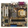
Product introduction Chapter 1 This chapter describes the features of the layout, jumper settings, and connectors. It includes brief descriptions of the motherboard components, and illustrations of the motherboard.
Product introduction Chapter 1 This chapter describes the features of the layout, jumper settings, and connectors. It includes brief descriptions of the motherboard components, and illustrations of the motherboard.
Motherboard DIY Troubleshooting Guide
Page 12
...® Pentium® 4 processor and the Intel® 845GE chipset to 2GB of system memory with the list below. 1.2 Package contents Check your motherboard package for the following items. ASUS P4GE-MX motherboard ASUS motherboard support CD 1 x IDE cable 1 x Floppy disk cable I/O shield Bag of extra jumper caps User guide If any of the above items is...
...® Pentium® 4 processor and the Intel® 845GE chipset to 2GB of system memory with the list below. 1.2 Package contents Check your motherboard package for the following items. ASUS P4GE-MX motherboard ASUS motherboard support CD 1 x IDE cable 1 x Floppy disk cable I/O shield Bag of extra jumper caps User guide If any of the above items is...
Motherboard DIY Troubleshooting Guide
Page 13
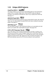
... This CODEC provides high-quality 6-channel audio, S/PDIF out support and connector sensing function without having to eight USB 2.0 ports. S/PDIF out The motherboard supports S/PDIF-out function turns your computer into a high-end entertainment system with digital connectivity to a fast 480 Mbps on USB 2.0 - 1.3 ...Pentium® 4 processor in the 478-pin package with 512/256KB L2 cache on USB 1.1 to powerful speaker systems. ASUS P4GE-MX motherboard 1-3 This motherboard supports 533/400 MHz system front side bus that allows 4.3GB/s and 3.2GB/s data transfer rates, respectively.
... This CODEC provides high-quality 6-channel audio, S/PDIF out support and connector sensing function without having to eight USB 2.0 ports. S/PDIF out The motherboard supports S/PDIF-out function turns your computer into a high-end entertainment system with digital connectivity to a fast 480 Mbps on USB 2.0 - 1.3 ...Pentium® 4 processor in the 478-pin package with 512/256KB L2 cache on USB 1.1 to powerful speaker systems. ASUS P4GE-MX motherboard 1-3 This motherboard supports 533/400 MHz system front side bus that allows 4.3GB/s and 3.2GB/s data transfer rates, respectively.
Motherboard DIY Troubleshooting Guide
Page 14
See page 2-4. ASUS MyLogo™ This new feature present in the motherboard allows you can easily update the system BIOS even before loading the operating system. This protection eliminates the need to your system with customizable boot ... case the system hangs due to overclocking, C.P.R. feature of the motherboard BIOS allows automatic re-setting to the BIOS previous settings in case the BIOS codes and data are corrupted. When the system hangs due to overclocking. ASUS EZ Flash BIOS The ASUS EZ Flash feature works through the Award BIOS Update utility...
See page 2-4. ASUS MyLogo™ This new feature present in the motherboard allows you can easily update the system BIOS even before loading the operating system. This protection eliminates the need to your system with customizable boot ... case the system hangs due to overclocking, C.P.R. feature of the motherboard BIOS allows automatic re-setting to the BIOS previous settings in case the BIOS codes and data are corrupted. When the system hangs due to overclocking. ASUS EZ Flash BIOS The ASUS EZ Flash feature works through the Award BIOS Update utility...
Motherboard DIY Troubleshooting Guide
Page 15
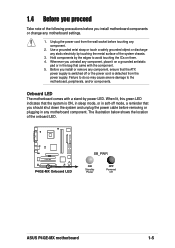
...component, place it on them. 4. Whenever you install motherboard components or change any motherboard settings. 1. The illustration below shows the location of the onboard LED. ® P4GE-MX P4GE-MX Onboard LED SB_PWR ON Standby Power OFF Powered Off ASUS P4GE-MX motherboard 1-5 Use a grounded wrist strap or touch a ... stand-by touching the metal surface of the system chassis. 3. Before you install or remove any motherboard component. Hold components by the edges to the motherboard, peripherals, and/or components. Failure to do so may cause severe damage to avoid touching the ...
...component, place it on them. 4. Whenever you install motherboard components or change any motherboard settings. 1. The illustration below shows the location of the onboard LED. ® P4GE-MX P4GE-MX Onboard LED SB_PWR ON Standby Power OFF Powered Off ASUS P4GE-MX motherboard 1-5 Use a grounded wrist strap or touch a ... stand-by touching the metal surface of the system chassis. 3. Before you install or remove any motherboard component. Hold components by the edges to the motherboard, peripherals, and/or components. Failure to do so may cause severe damage to avoid touching the ...

Motherboard DIY Troubleshooting Guide
Page 16
1.5 Motherboard overview 1.5.1 Motherboard layout 21.9cm (8.6in) PS/2KBMS T: Mouse B: Keyboard COM1 Socket 478 CPU_FAN Super I/O ATX Power Connector FLOPPY1 DDR DIMM1 (64/72 bit, 184-pin module) ... RJ-45 USBPWR_34 ATX12V1 Top:Line In Center:Line Out Below:Mic In Intel 82845GE Memory Controller Hub FP_AUDIO Accelerated Graphics Port (AGP) R RTL8100C PCI1 P4GE-MX PCI2 Intel 82801DB ICH4 3Mbit Firmware Hub Audio Codec SPDIF_OUT CD PCI3 CHA_FAN AUX SB_PWR COM2 USBPWR_56 USB56 GAME1 CR2032 3V Lithium Cell CLRTC CMOS...
1.5 Motherboard overview 1.5.1 Motherboard layout 21.9cm (8.6in) PS/2KBMS T: Mouse B: Keyboard COM1 Socket 478 CPU_FAN Super I/O ATX Power Connector FLOPPY1 DDR DIMM1 (64/72 bit, 184-pin module) ... RJ-45 USBPWR_34 ATX12V1 Top:Line In Center:Line Out Below:Mic In Intel 82845GE Memory Controller Hub FP_AUDIO Accelerated Graphics Port (AGP) R RTL8100C PCI1 P4GE-MX PCI2 Intel 82801DB ICH4 3Mbit Firmware Hub Audio Codec SPDIF_OUT CD PCI3 CHA_FAN AUX SB_PWR COM2 USBPWR_56 USB56 GAME1 CR2032 3V Lithium Cell CLRTC CMOS...
Motherboard DIY Troubleshooting Guide
Page 17
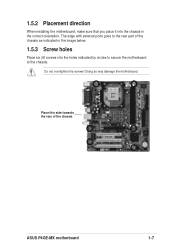
1.5.2 Placement direction When installing the motherboard, make sure that you place it into the holes indicated by circles to secure the motherboard to the rear part of the chassis ASUS P4GE-MX motherboard 1-7 Place this side towards the rear of the chassis as indicated in the image below. 1.5.3 Screw holes Place six (6) screws into the chassis in the correct orientation. Do not overtighten the screws! The edge with external ports goes to the chassis. Doing so may damage the motherboard.
1.5.2 Placement direction When installing the motherboard, make sure that you place it into the holes indicated by circles to secure the motherboard to the rear part of the chassis ASUS P4GE-MX motherboard 1-7 Place this side towards the rear of the chassis as indicated in the image below. 1.5.3 Screw holes Place six (6) screws into the chassis in the correct orientation. Do not overtighten the screws! The edge with external ports goes to the chassis. Doing so may damage the motherboard.

Motherboard DIY Troubleshooting Guide
Page 18
... a specific corner on Hyper-Threading Technology, visit www.intel.com/ info/hyperthreading. 1-8 Chapter 1: Product introduction This motherboard supports Intel® Pentium® 4 CPUs with gold triangle) on Intel® Hyper-Threading Technology 1. Make sure...P4GE-MX P4GE-MX CPU Socket 478 Incorrect installation of the marked corner (with Hyper-Threading Technology. 2. If you install Windows® XP Service Pack 1. 4. Under Linux, use the Hyper-Threading compliler to ensure system stability and performance. 3. 1.6 Central Processing Unit (CPU) 1.6.1 Overview The motherboard...
... a specific corner on Hyper-Threading Technology, visit www.intel.com/ info/hyperthreading. 1-8 Chapter 1: Product introduction This motherboard supports Intel® Pentium® 4 CPUs with gold triangle) on Intel® Hyper-Threading Technology 1. Make sure...P4GE-MX P4GE-MX CPU Socket 478 Incorrect installation of the marked corner (with Hyper-Threading Technology. 2. If you install Windows® XP Service Pack 1. 4. Under Linux, use the Hyper-Threading compliler to ensure system stability and performance. 3. 1.6 Central Processing Unit (CPU) 1.6.1 Overview The motherboard...

Motherboard DIY Troubleshooting Guide
Page 19
... steps to 90°-100° angle; Carefully insert the CPU into the socket to a 90°- 100° angle. The lever clicks on the motherboard. 2. Locate the 478-pin ZIF socket on the side tab to secure the CPU. The CPU fits only in completely. 3. Gold Mark 4. otherwise, the CPU.... DO NOT force the CPU into the socket until it is in place, push down the socket lever to indicate that it fits in place. ASUS P4GE-MX motherboard 1-9 When the CPU is locked. Unlock the socket by pressing the lever sideways, then lift it up to install a CPU. 1.
... steps to 90°-100° angle; Carefully insert the CPU into the socket to a 90°- 100° angle. The lever clicks on the motherboard. 2. Locate the 478-pin ZIF socket on the side tab to secure the CPU. The CPU fits only in completely. 3. Gold Mark 4. otherwise, the CPU.... DO NOT force the CPU into the socket until it is in place, push down the socket lever to indicate that it fits in place. ASUS P4GE-MX motherboard 1-9 When the CPU is locked. Unlock the socket by pressing the lever sideways, then lift it up to install a CPU. 1.

Motherboard DIY Troubleshooting Guide
Page 20
... DIMM sockets. 80 Pins ® P4GE-MX 104 Pins P4GE-MX 184-Pin DDR DIMM Sockets Make sure to unplug the power supply before adding or removing DIMMs or other system components. Failure to do so may cause severe damage to both the motherboard and the components. 1.7.2 Installing a... DDR DIMM is properly seated. DO NOT force a DIMM into a socket to install a DIMM. 1. The following figure illustrates the location of this motherboard. 1.7 System memory 1.7.1 DIMM sockets location You can install 64MB, 256MB, 512MB, and 1GB DDR DIMMs into the socket until the retaining clips snap ...
... DIMM sockets. 80 Pins ® P4GE-MX 104 Pins P4GE-MX 184-Pin DDR DIMM Sockets Make sure to unplug the power supply before adding or removing DIMMs or other system components. Failure to do so may cause severe damage to both the motherboard and the components. 1.7.2 Installing a... DDR DIMM is properly seated. DO NOT force a DIMM into a socket to install a DIMM. 1. The following figure illustrates the location of this motherboard. 1.7 System memory 1.7.1 DIMM sockets location You can install 64MB, 256MB, 512MB, and 1GB DDR DIMMs into the socket until the retaining clips snap ...
Motherboard DIY Troubleshooting Guide
Page 21
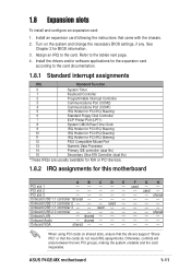
used - - - - PCI slot 3 shared Onboard USB 1.1 controller 1shared Onboard USB 1.1 controller 2 - - - Onboard Audio - ASUS P4GE-MX motherboard 1-11 Refer to the card. used - - Otherwise, conflicts will arise between the two PCI groups, making the system unstable and the card inoperable. See Chapter 2 for this motherboard A B C D E F G H PCI slot 1 - - - - - PCI slot 2 - - - - - - shared - - - - - - Assign an IRQ to the tables...
used - - - - PCI slot 3 shared Onboard USB 1.1 controller 1shared Onboard USB 1.1 controller 2 - - - Onboard Audio - ASUS P4GE-MX motherboard 1-11 Refer to the card. used - - Otherwise, conflicts will arise between the two PCI groups, making the system unstable and the card inoperable. See Chapter 2 for this motherboard A B C D E F G H PCI slot 1 - - - - - PCI slot 2 - - - - - - shared - - - - - - Assign an IRQ to the tables...

Motherboard DIY Troubleshooting Guide
Page 22
When you buy an AGP card, make sure that you ask for 1.5v P4GE-MX Accelerated Graphics Port (AGP) 1-12 Chapter 1: Product introduction Install only +1.5V AGP cards. ® P4GE-MX Keyed for one with PCI specifications. 1.8.4 AGP slot The Accelerated Graphics Port (AGP) slot supports AGP 4X (+1.5V) cards. 1.8.3 PCI slots The PCI slots support PCI cards such as a LAN card, SCSI card, USB card, and other cards that comply with +1.5V specification. Note the notches on the card golden fingers to ensure that they fit the AGP slot on the motherboard.
When you buy an AGP card, make sure that you ask for 1.5v P4GE-MX Accelerated Graphics Port (AGP) 1-12 Chapter 1: Product introduction Install only +1.5V AGP cards. ® P4GE-MX Keyed for one with PCI specifications. 1.8.4 AGP slot The Accelerated Graphics Port (AGP) slot supports AGP 4X (+1.5V) cards. 1.8.3 PCI slots The PCI slots support PCI cards such as a LAN card, SCSI card, USB card, and other cards that comply with +1.5V specification. Note the notches on the card golden fingers to ensure that they fit the AGP slot on the motherboard.

Motherboard DIY Troubleshooting Guide
Page 23
1.9 Jumpers 1. Plug the power cord and turn ON the computer. 4. ASUS P4GE-MX motherboard 1-13 To erase the RTC RAM: 1. Removing the cap will cause system boot failure! ® P4GE-MX P4GE-MX Clear RTC RAM CLRTC 12 23 Clear CMOS Normal (Default) You do not need to clear the RTC when the system hangs due to pins 2-3. 3. ...
1.9 Jumpers 1. Plug the power cord and turn ON the computer. 4. ASUS P4GE-MX motherboard 1-13 To erase the RTC RAM: 1. Removing the cap will cause system boot failure! ® P4GE-MX P4GE-MX Clear RTC RAM CLRTC 12 23 Clear CMOS Normal (Default) You do not need to clear the RTC when the system hangs due to pins 2-3. 3. ...
Motherboard DIY Troubleshooting Guide
Page 25
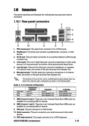
1.10 Connectors This section describes and illustrates the motherboard rear panel and internal connectors. 1.10.1 Rear panel connectors 1 2 3 4 5 6 11 10 9 8 7 1. In 6-channel mode, the function of the Line Out, Line In...2. These two 4-pin Universal Serial Bus (USB) ports are available for a PS/2 keyboard. This port connects to a Local Area Network (LAN) through a network hub. 4. ASUS P4GE-MX motherboard 1-15 USB 2.0 ports 1 and 2. VGA port. This green 6-pin connector is for connecting USB 2.0 devices. 8. Parallel port. This Line In (light blue) jack connects ...
1.10 Connectors This section describes and illustrates the motherboard rear panel and internal connectors. 1.10.1 Rear panel connectors 1 2 3 4 5 6 11 10 9 8 7 1. In 6-channel mode, the function of the Line Out, Line In...2. These two 4-pin Universal Serial Bus (USB) ports are available for a PS/2 keyboard. This port connects to a Local Area Network (LAN) through a network hub. 4. ASUS P4GE-MX motherboard 1-15 USB 2.0 ports 1 and 2. VGA port. This green 6-pin connector is for connecting USB 2.0 devices. 8. Parallel port. This Line In (light blue) jack connects ...

Motherboard DIY Troubleshooting Guide
Page 26
... the floppy drive. (Pin 5 is intentional. P4GE-MX IDE connectors PIN 1 2. After connecting one end to the motherboard, connect the other end to PIN 1. PIN 1 P4GE-MX Floppy disk drive connector 1-16 Chapter 1: Product introduction FLOPPY1 ® P4GE-MX NOTE: Orient the red markings on the Ultra DMA...blue connector on the IDE ribbon cable to prevent incorrect insertion when using ribbon cables with pin 5 plug). SEC_IDE PRI_IDE ® P4GE-MX NOTE: Orient the red markings (usually zigzag) on the Ultra DMA cable is removed to PIN 1. Floppy disk drive connector (34...
... the floppy drive. (Pin 5 is intentional. P4GE-MX IDE connectors PIN 1 2. After connecting one end to the motherboard, connect the other end to PIN 1. PIN 1 P4GE-MX Floppy disk drive connector 1-16 Chapter 1: Product introduction FLOPPY1 ® P4GE-MX NOTE: Orient the red markings on the Ultra DMA...blue connector on the IDE ribbon cable to prevent incorrect insertion when using ribbon cables with pin 5 plug). SEC_IDE PRI_IDE ® P4GE-MX NOTE: Orient the red markings (usually zigzag) on the Ultra DMA cable is removed to PIN 1. Floppy disk drive connector (34...
Motherboard DIY Troubleshooting Guide
Page 27
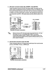
... the +5-volt standby lead (+5VSB). Left Audio Channel Ground Ground Right Audio Channel Left Audio Channel Ground Ground Right Audio Channel ® P4GE-MX CD(Black) AUX(White) P4GE-MX Internal audio connectors ASUS P4GE-MX motherboard 1-17 The plugs from sound sources such as a CD-ROM, TV tuner, or MPEG card. The minimum recommended wattage is inadequate...
... the +5-volt standby lead (+5VSB). Left Audio Channel Ground Ground Right Audio Channel Left Audio Channel Ground Ground Right Audio Channel ® P4GE-MX CD(Black) AUX(White) P4GE-MX Internal audio connectors ASUS P4GE-MX motherboard 1-17 The plugs from sound sources such as a CD-ROM, TV tuner, or MPEG card. The minimum recommended wattage is inadequate...
Motherboard DIY Troubleshooting Guide
Page 28
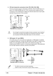
.... 5. DO NOT place jumper caps on the motherboard, making sure that the black wire of each cable matches the ground pin of the USB 2.0 module to the fan connectors. CPU_FAN Rotation +12V GND ® P4GE-MX CHA_FAN Rotation +12V GND P4GE-MX Fan connectors Do not forget to connect the fan ...header. USB header (10-1 pin USB56) If the USB ports on the rear panel are not jumpers! USB+5V LDM5 LDP5 GND NC ® P4GE-MX P4GE-MX USB 2.0 connector USB56 1 USB+5V LDM6 LDP6 GND • The USB 2.0 module is available for connecting next generation USB peripherals such as high...
.... 5. DO NOT place jumper caps on the motherboard, making sure that the black wire of each cable matches the ground pin of the USB 2.0 module to the fan connectors. CPU_FAN Rotation +12V GND ® P4GE-MX CHA_FAN Rotation +12V GND P4GE-MX Fan connectors Do not forget to connect the fan ...header. USB header (10-1 pin USB56) If the USB ports on the rear panel are not jumpers! USB+5V LDM5 LDP5 GND NC ® P4GE-MX P4GE-MX USB 2.0 connector USB56 1 USB+5V LDM6 LDP6 GND • The USB 2.0 module is available for connecting next generation USB peripherals such as high...


