
K8V-X user's manual
Page 1
Motherboard K8V-X User Guide
Motherboard K8V-X User Guide

K8V-X user's manual
Page 3
... vi Safety information vii About this guide viii Conventions used in this guide viii Typography viii K8V-X specifications summary ix Chapter 1: Product introduction 1.1 Welcome 1-2 1.2 Package contents 1-2 1.3 Special features 1-3 1.3.1 Product Highlights 1-3 1.3.2 Unique ASUS features 1-4 1.4 Before you proceed 1-5 1.5 Motherboard overview 1-6 1.5.1 Motherboard layout 1-6 1.5.2 Placement direction 1-7 1.5.3 Screw holes 1-7 1.6 Central Processing Unit (CPU 1-8 1.6.1 Overview 1-8 1.6.2 Installing the CPU 1-9 1.7 System memory...
... vi Safety information vii About this guide viii Conventions used in this guide viii Typography viii K8V-X specifications summary ix Chapter 1: Product introduction 1.1 Welcome 1-2 1.2 Package contents 1-2 1.3 Special features 1-3 1.3.1 Product Highlights 1-3 1.3.2 Unique ASUS features 1-4 1.4 Before you proceed 1-5 1.5 Motherboard overview 1-6 1.5.1 Motherboard layout 1-6 1.5.2 Placement direction 1-7 1.5.3 Screw holes 1-7 1.6 Central Processing Unit (CPU 1-8 1.6.1 Overview 1-8 1.6.2 Installing the CPU 1-9 1.7 System memory...

K8V-X user's manual
Page 7
... paper clips, screws, and staples away from connectors, slots, sockets and circuitry. • Avoid dust, humidity, and temperature extremes. Operation safety • Before installing the motherboard and adding devices on a stable surface. • If you are using, contact your local power company. • If the power supply is set to fix... correctly connected and the power cables are not damaged. These devices could interrupt the grounding circuit. • Make sure that all power cables from the motherboard, ensure that your area.
... paper clips, screws, and staples away from connectors, slots, sockets and circuitry. • Avoid dust, humidity, and temperature extremes. Operation safety • Before installing the motherboard and adding devices on a stable surface. • If you are using, contact your local power company. • If the power supply is set to fix... correctly connected and the power cables are not damaged. These devices could interrupt the grounding circuit. • Make sure that all power cables from the motherboard, ensure that your area.

K8V-X user's manual
Page 11
Chapter 1 This chapter describes the features of the layout, jumper settings, and connectors. Product introduction It includes brief descriptions of the motherboard components, and illustrations of the motherboard.
Chapter 1 This chapter describes the features of the layout, jumper settings, and connectors. Product introduction It includes brief descriptions of the motherboard components, and illustrations of the motherboard.

K8V-X user's manual
Page 12
... the powers of the above items is damaged or missing, contact your motherboard package for the following items. ASUS K8V-X motherboard ASUS motherboard support CD 1 x Ultra DMA 133/100/66 cables 2 x Serial ATA cables 1 x IDE cable 1 x Floppy disk cable I/O shield Bag of...AGP 8X slot, Serial ATA RAID, USB 2.0, and 6-channel audio features, the motherboard takes you for an effective desktop platform solution. Supporting up to set a new benchmark for buying the ASUS® K8V-X motherboard! The motherboard delivers a host of new features and latest technologies making it , check the ...
... the powers of the above items is damaged or missing, contact your motherboard package for the following items. ASUS K8V-X motherboard ASUS motherboard support CD 1 x Ultra DMA 133/100/66 cables 2 x Serial ATA cables 1 x IDE cable 1 x Floppy disk cable I/O shield Bag of...AGP 8X slot, Serial ATA RAID, USB 2.0, and 6-channel audio features, the motherboard takes you for an effective desktop platform solution. Supporting up to set a new benchmark for buying the ASUS® K8V-X motherboard! The motherboard delivers a host of new features and latest technologies making it , check the ...

K8V-X user's manual
Page 13
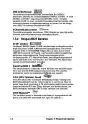
...GB/s. Cool 'n' Quiet!™ Technology The motherboard supports the AMD® Cool 'n' Quiet!™ Technology that enhance hard disk performance and data backup protection without the cost of up to powerful speaker systems. ASUS K8V-X motherboard 1-3 The Serial ATA specification allows for RAID ...0 and RAID 1 functions. S/PDIF out The motherboard's S/PDIF out function turns your computer into a high-end entertainment system...
...GB/s. Cool 'n' Quiet!™ Technology The motherboard supports the AMD® Cool 'n' Quiet!™ Technology that enhance hard disk performance and data backup protection without the cost of up to powerful speaker systems. ASUS K8V-X motherboard 1-3 The Serial ATA specification allows for RAID ...0 and RAID 1 functions. S/PDIF out The motherboard's S/PDIF out function turns your computer into a high-end entertainment system...
K8V-X user's manual
Page 14
...) applications. CrashFree BIOS 2 This feature allows you enjoy high-quality 6-channel audio without having to overclocking. ASUS MyLogo2™ This new feature present in the motherboard allows you to personalize and add style to your system with the net-diagnosing utility VCT (Virtual Cable Tester), ...that lets you to restore the original BIOS data from the ASUS support CD in case the system hangs due to buy a replacement ROM chip. The higher bandwidth of USB 2.0 allows connection of the motherboard BIOS allows automatic re-setting to 100 meters. This feature helps maintain...
...) applications. CrashFree BIOS 2 This feature allows you enjoy high-quality 6-channel audio without having to overclocking. ASUS MyLogo2™ This new feature present in the motherboard allows you to personalize and add style to your system with the net-diagnosing utility VCT (Virtual Cable Tester), ...that lets you to restore the original BIOS data from the ASUS support CD in case the system hangs due to buy a replacement ROM chip. The higher bandwidth of USB 2.0 allows connection of the motherboard BIOS allows automatic re-setting to 100 meters. This feature helps maintain...

K8V-X user's manual
Page 15
...music! No need to static electricity. 3. Failure to do so may cause severe damage to Windows®. K8V-X ® K8V-X Onboard LED SB_PWR ON Standby Power OFF Powered Off ASUS K8V-X motherboard 1-5 See page 2-5. Use a grounded wrist strap or touch a safely grounded object or to avoid damaging...from the power supply. ASUS EZ Flash BIOS With the ASUS EZ Flash, you can easily update the system BIOS even before you install motherboard components or change any motherboard settings. 1. See details on a grounded antistatic pad or in any motherboard component. Whenever you to...
...music! No need to static electricity. 3. Failure to do so may cause severe damage to Windows®. K8V-X ® K8V-X Onboard LED SB_PWR ON Standby Power OFF Powered Off ASUS K8V-X motherboard 1-5 See page 2-5. Use a grounded wrist strap or touch a safely grounded object or to avoid damaging...from the power supply. ASUS EZ Flash BIOS With the ASUS EZ Flash, you can easily update the system BIOS even before you install motherboard components or change any motherboard settings. 1. See details on a grounded antistatic pad or in any motherboard component. Whenever you to...

K8V-X user's manual
Page 16
PRI_IDE 1.5 Motherboard overview 1.5.1 Motherboard layout PS/2KBMS T: Mouse B: Keyboard KBPWR ATX12V 24.5cm (9.6in) CPU_FAN SPDIF_O DDR DIMM1 (64 bit,184-pin module) DDR DIMM2 (64 bit,184-pin ... CD ADI AD1980 AUX FP_AUDIO FLOPPY Accelerated Graphics Port (AGP) PCI1 PCI2 PCI3 CR2032 3V Lithium Cell CMOS Power VIA VT8237 SATA2 SATA1 PCI4 ® K8V-X PCI5 USBPWR56 USBPWR78 USB78 USB56 CLRTC Super 4Mbit I/O BIOS CHASSIS SB_PWR GAME PANEL SEC_IDE 30.5cm (12.0in) CHA_FAN 1-6 Chapter 1: Product introduction
PRI_IDE 1.5 Motherboard overview 1.5.1 Motherboard layout PS/2KBMS T: Mouse B: Keyboard KBPWR ATX12V 24.5cm (9.6in) CPU_FAN SPDIF_O DDR DIMM1 (64 bit,184-pin module) DDR DIMM2 (64 bit,184-pin ... CD ADI AD1980 AUX FP_AUDIO FLOPPY Accelerated Graphics Port (AGP) PCI1 PCI2 PCI3 CR2032 3V Lithium Cell CMOS Power VIA VT8237 SATA2 SATA1 PCI4 ® K8V-X PCI5 USBPWR56 USBPWR78 USB78 USB56 CLRTC Super 4Mbit I/O BIOS CHASSIS SB_PWR GAME PANEL SEC_IDE 30.5cm (12.0in) CHA_FAN 1-6 Chapter 1: Product introduction
K8V-X user's manual
Page 17
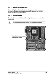
1.5.2 Placement direction When installing the motherboard, make sure that you place it into the holes indicated by circles to secure the motherboard to the rear part of the chassis ASUS K8V-X motherboard 1-7 Doing so may damage the motherboard. Do not overtighten the screws! The edge with external ports goes to the chassis. Place this side towards the rear of the chassis as indicated in the image below. 1.5.3 Screw holes Place nine (9) screws into the chassis in the correct orientation.
1.5.2 Placement direction When installing the motherboard, make sure that you place it into the holes indicated by circles to secure the motherboard to the rear part of the chassis ASUS K8V-X motherboard 1-7 Doing so may damage the motherboard. Do not overtighten the screws! The edge with external ports goes to the chassis. Place this side towards the rear of the chassis as indicated in the image below. 1.5.3 Screw holes Place nine (9) screws into the chassis in the correct orientation.

K8V-X user's manual
Page 18
1.6 Central Processing Unit (CPU) 1.6.1 Overview The motherboard comes with only 32-bit or 64-bit wide data paths. The 128-bit-wide data paths of the CPU into the socket may bend the pins and severely damage the CPU! 1-8 Chapter 1: Product introduction K8V-X ® K8V-X Socket 754 Gold Arrow Incorrect installation of these processors can run applications faster than processors with a surface mount 754-pin Zero Insertion Force (ZIF) socket designed for the AMD Athlon™ 64 processor.
1.6 Central Processing Unit (CPU) 1.6.1 Overview The motherboard comes with only 32-bit or 64-bit wide data paths. The 128-bit-wide data paths of the CPU into the socket may bend the pins and severely damage the CPU! 1-8 Chapter 1: Product introduction K8V-X ® K8V-X Socket 754 Gold Arrow Incorrect installation of these processors can run applications faster than processors with a surface mount 754-pin Zero Insertion Force (ZIF) socket designed for the AMD Athlon™ 64 processor.
K8V-X user's manual
Page 19
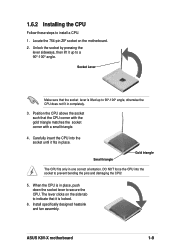
... a CPU. 1. Position the CPU above the socket such that it is lifted up to prevent bending the pins and damaging the CPU! 5. ASUS K8V-X motherboard 1-9 The lever clicks on the motherboard. 2. Install specifically designed heatsink and fan assembly. Socket Lever Make sure that the socket lever is locked. 6. Small triangle Gold triangle The CPU...
... a CPU. 1. Position the CPU above the socket such that it is lifted up to prevent bending the pins and damaging the CPU! 5. ASUS K8V-X motherboard 1-9 The lever clicks on the motherboard. 2. Install specifically designed heatsink and fan assembly. Socket Lever Make sure that the socket lever is locked. 6. Small triangle Gold triangle The CPU...

K8V-X user's manual
Page 20
... Pins K8V-X ® K8V-X 184-Pin DDR DIMM Sockets • It is recommended to unplug the power supply before adding or removing DIMMs or other than 18 chips are not supported. • Always install DIMMs with the same CAS Latency. Failure to do so may cause severe damage to both the motherboard and...
... Pins K8V-X ® K8V-X 184-Pin DDR DIMM Sockets • It is recommended to unplug the power supply before adding or removing DIMMs or other than 18 chips are not supported. • Always install DIMMs with the same CAS Latency. Failure to do so may cause severe damage to both the motherboard and...

K8V-X user's manual
Page 21
... 400 DDR 400 DDR 400 DDR 333 DDR 333 DDR 400 DDR 333 DDR 333 DDR 333 DDR 333 DDR 333 DDR 333 DDR 333 ASUS K8V-X motherboard 1-11 Double Side -
... 400 DDR 400 DDR 400 DDR 333 DDR 333 DDR 400 DDR 333 DDR 333 DDR 333 DDR 333 DDR 333 DDR 333 DDR 333 ASUS K8V-X motherboard 1-11 Double Side -

K8V-X user's manual
Page 22
Obtain DDR DIMMs only from ASUS qualified vendors for better system performance. 1-12 Chapter 1: Product introduction Table 2 DDR400 Qualified Vendor List (QVL) Size SS/DS 256MB SS 512MB DS 256MB SS ... M368L6423FTN-CCC HYMD232646B8J-D43 AA HYMD264646B8J-D43 AA MT8VDDT3264AG-40BCB MT16VDDT6464AG-40BCB HYS64D32300GU-5-B HYS64D64320GU-5-B HYS64D32300HU-5-C CMX512-3200C2 Visit the ASUS website (www.asus.com) for the latest DDR 400 Qualified Vendor List for this motherboard. DDR Qualified Vendor List The following table lists the PC3200 (DDR400) memory modules that have been tested and...
Obtain DDR DIMMs only from ASUS qualified vendors for better system performance. 1-12 Chapter 1: Product introduction Table 2 DDR400 Qualified Vendor List (QVL) Size SS/DS 256MB SS 512MB DS 256MB SS ... M368L6423FTN-CCC HYMD232646B8J-D43 AA HYMD264646B8J-D43 AA MT8VDDT3264AG-40BCB MT16VDDT6464AG-40BCB HYS64D32300GU-5-B HYS64D64320GU-5-B HYS64D32300HU-5-C CMX512-3200C2 Visit the ASUS website (www.asus.com) for the latest DDR 400 Qualified Vendor List for this motherboard. DDR Qualified Vendor List The following table lists the PC3200 (DDR400) memory modules that have been tested and...

K8V-X user's manual
Page 23
... BIOS information. 3. DO NOT force a DIMM into the socket until the retaining clips snap back in place and the DIMM is keyed with the chassis. 2. ASUS K8V-X motherboard 1-13 Unlock a DIMM socket by pressing the retaining clips outward. 2. Align a DIMM on the system and change the necessary BIOS settings, if any.
... BIOS information. 3. DO NOT force a DIMM into the socket until the retaining clips snap back in place and the DIMM is keyed with the chassis. 2. ASUS K8V-X motherboard 1-13 Unlock a DIMM socket by pressing the retaining clips outward. 2. Align a DIMM on the system and change the necessary BIOS settings, if any.

K8V-X user's manual
Page 24
... PCI cards such as a LAN card, SCSI card, USB card, and other cards that the cards do not need IRQ assignments. 1.8.2 IRQ assignments for this motherboard PCI slot 1 PCI slot 2 PCI slot 3 PCI slot 4 PCI slot 5 Gigabit LAN AGP slot INT A shared - - - shared - - - - used - - - INT D - - - shared - shared - shared INT B - INT...
... PCI cards such as a LAN card, SCSI card, USB card, and other cards that the cards do not need IRQ assignments. 1.8.2 IRQ assignments for this motherboard PCI slot 1 PCI slot 2 PCI slot 3 PCI slot 4 PCI slot 5 Gigabit LAN AGP slot INT A shared - - - shared - - - - used - - - INT D - - - shared - shared - shared INT B - INT...
K8V-X user's manual
Page 25
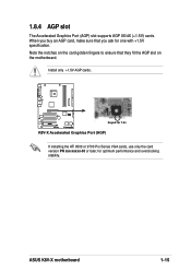
K8V-X Keyed for 1.5v ® K8V-X Accelerated Graphics Port (AGP) If installing the ATi 9500 or 9700 Pro Series VGA cards, use only the card version PN xxx-xxxxx-30 or later, for one with +1.5V specification. When you ask for optimum performance and overclocking stability. 1.8.4 AGP slot The Accelerated Graphics Port (AGP) slot supports AGP 8X/4X (+1.5V) cards. Install only +1.5V AGP cards. Note the notches on the card golden fingers to ensure that you buy an AGP card, make sure that they fit the AGP slot on the motherboard. ASUS K8V-X motherboard 1-15
K8V-X Keyed for 1.5v ® K8V-X Accelerated Graphics Port (AGP) If installing the ATi 9500 or 9700 Pro Series VGA cards, use only the card version PN xxx-xxxxx-30 or later, for one with +1.5V specification. When you ask for optimum performance and overclocking stability. 1.8.4 AGP slot The Accelerated Graphics Port (AGP) slot supports AGP 8X/4X (+1.5V) cards. Install only +1.5V AGP cards. Note the notches on the card golden fingers to ensure that you buy an AGP card, make sure that they fit the AGP slot on the motherboard. ASUS K8V-X motherboard 1-15
K8V-X user's manual
Page 27
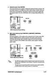
... a key on the +5VSB lead, and a corresponding setting in reduced power mode). ASUS K8V-X motherboard 1-17 KBPWR 12 23 +5V +5VSB (Default) K8V-X ® K8V-X Keyboard Power Setting 3. 2. USBPWR12 USBPWR34 2 1 +5V (Default) 3 2 +5VSB 12 +5V (Default) 23 +5VSB K8V-X USBPWR56 USBPWR78 12 23 ® K8V-X USB Device Wake Up +5V (Default) +5VSB • The USB device wake...
... a key on the +5VSB lead, and a corresponding setting in reduced power mode). ASUS K8V-X motherboard 1-17 KBPWR 12 23 +5V +5VSB (Default) K8V-X ® K8V-X Keyboard Power Setting 3. 2. USBPWR12 USBPWR34 2 1 +5V (Default) 3 2 +5VSB 12 +5V (Default) 23 +5VSB K8V-X USBPWR56 USBPWR78 12 23 ® K8V-X USB Device Wake Up +5V (Default) +5VSB • The USB device wake...

K8V-X user's manual
Page 28
..., the function of this jack becomes Bass/Center. 5. Line Out jack. This Mic (pink) jack connects a microphone. 1.10 Connectors This section describes and illustrates the motherboard rear panel and internal connectors. 1.10.1 Rear panel connectors 1 2 3 4 5 6 11 10 9 8 7 1. In 6-channel mode, the function of this jack becomes Rear Speaker Out. This Line...
..., the function of this jack becomes Bass/Center. 5. Line Out jack. This Mic (pink) jack connects a microphone. 1.10 Connectors This section describes and illustrates the motherboard rear panel and internal connectors. 1.10.1 Rear panel connectors 1 2 3 4 5 6 11 10 9 8 7 1. In 6-channel mode, the function of this jack becomes Rear Speaker Out. This Line...


