User Manual
Page 11
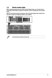
LAN 2 LAN 1 DM ASUS ESC8000A-E12 1-3 With the correct serial number of the product's serial number containing 12 characters, such as xxSxxxxxxxxx. See the figure below. 1.2 Serial number label Before requesting support from the ASUS Technical Support team, you must take note of the product, ASUS Technical Support team members can then offer a quicker and satisfying solution to your problems. ESC8000A-E12 xxSxxxxxxxxx Q code CLEAR CMOS RESET LAN 1 LAN 2 M.2 The serial number is printed on the Asset tag.
LAN 2 LAN 1 DM ASUS ESC8000A-E12 1-3 With the correct serial number of the product's serial number containing 12 characters, such as xxSxxxxxxxxx. See the figure below. 1.2 Serial number label Before requesting support from the ASUS Technical Support team, you must take note of the product, ASUS Technical Support team members can then offer a quicker and satisfying solution to your problems. ESC8000A-E12 xxSxxxxxxxxx Q code CLEAR CMOS RESET LAN 1 LAN 2 M.2 The serial number is printed on the Asset tag.
User Manual
Page 12
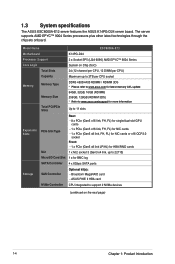
1.3 System specifications The ASUS ESC8000A-E12 server features the ASUS K14PG-D24 server board. ASUS PIKE II HBA card NVMe Controller CPU integrated to support 2 NVMe devices (continued on Chip (SoC) 24 (12-channel per CPU, 12 DIMM ...Controller Optional kit(s): - The server supports AMD EPYC™ 9004 Series processors plus other latest technologies through the chipsets onboard. Broadcom MegaRAID card - Model Name ESC8000A-E12 Motherboard Processor Support Core Logic Total Slots K14PG-D24 2 x Socket SP5 (LGA 6096) AMD EPYC™ 9004 Series System on the next page) 1-4 ...
1.3 System specifications The ASUS ESC8000A-E12 server features the ASUS K14PG-D24 server board. ASUS PIKE II HBA card NVMe Controller CPU integrated to support 2 NVMe devices (continued on Chip (SoC) 24 (12-channel per CPU, 12 DIMM ...Controller Optional kit(s): - The server supports AMD EPYC™ 9004 Series processors plus other latest technologies through the chipsets onboard. Broadcom MegaRAID card - Model Name ESC8000A-E12 Motherboard Processor Support Core Logic Total Slots K14PG-D24 2 x Socket SP5 (LGA 6096) AMD EPYC™ 9004 Series System on the next page) 1-4 ...
User Manual
Page 13
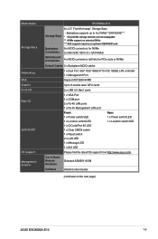
... CMOS switch 1 x Reset switch 2 x LAN LED 1 x Message LED 1 x M.2 LED Please find the latest OS support from http://www.asus.com/ Out of Band Remote Hardware Onboard ASMB11-iKVM Software ASUS Control Center (continued on the next page) ASUS ESC8000A-E12 1-5 Model Name Storage Bays Networking VGA Graphic Front I/O Rear I/O Switch/LED OS Support Management Solution...
... CMOS switch 1 x Reset switch 2 x LAN LED 1 x Message LED 1 x M.2 LED Please find the latest OS support from http://www.asus.com/ Out of Band Remote Hardware Onboard ASMB11-iKVM Software ASUS Control Center (continued on the next page) ASUS ESC8000A-E12 1-5 Model Name Storage Bays Networking VGA Graphic Front I/O Rear I/O Switch/LED OS Support Management Solution...

User Manual
Page 15
1.4 Front panel features The barebone server features a simple yet stylish front panel. ASUS ESC8000A-E12 1-7 Power switch/LED Location switch/LED Q-Code LED USB 3.2 Gen 1 ports Asset tag (hidden) Clear CMOS switch Reset switch LAN LEDs Message LED Full-Height, ... Redundant power supply units Power switch/LED DM DM port* VGA Port Redundant power supply unit COM Port The DM (Dedicated Management) port is for ASUS ASMB11-iKVM only. The power and reset buttons, LED indicators, and USB ports are located on the rear panel of the server.
1.4 Front panel features The barebone server features a simple yet stylish front panel. ASUS ESC8000A-E12 1-7 Power switch/LED Location switch/LED Q-Code LED USB 3.2 Gen 1 ports Asset tag (hidden) Clear CMOS switch Reset switch LAN LEDs Message LED Full-Height, ... Redundant power supply units Power switch/LED DM DM port* VGA Port Redundant power supply unit COM Port The DM (Dedicated Management) port is for ASUS ASMB11-iKVM only. The power and reset buttons, LED indicators, and USB ports are located on the rear panel of the server.
User Manual
Page 17
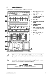
GPU fans 4. ASUS K14PG-D24 server board 5. Remove the protection film before shipping. Connect a USB floppy disk drive to any of the USB ports on the front or ... use a floppy disk. PCIe riser card with full-height/full-length PCIe expansion slots 3. WARNING HAZARDOUS MOVING PARTS KEEP FINGERS AND OTHER BODY PARTS AWAY ASUS ESC8000A-E12 1-9 1.7 Internal features The barebone server includes the basic components as shown. 1. GPU SKU board with lowprofile/half-length slot The barebone server does not include...
GPU fans 4. ASUS K14PG-D24 server board 5. Remove the protection film before shipping. Connect a USB floppy disk drive to any of the USB ports on the front or ... use a floppy disk. PCIe riser card with full-height/full-length PCIe expansion slots 3. WARNING HAZARDOUS MOVING PARTS KEEP FINGERS AND OTHER BODY PARTS AWAY ASUS ESC8000A-E12 1-9 1.7 Internal features The barebone server includes the basic components as shown. 1. GPU SKU board with lowprofile/half-length slot The barebone server does not include...

User Manual
Page 19
1.8.2 Rear panel LEDs LAN 2 LAN 1 DM Location button with LED LAN 1 LAN 2 M.2 Power button with LED LED Power button with LED Location button with LED Icon Display status Description ON System power on ON Location switch is pressed (Press the location switch again to turn off) OFF Function off ASUS ESC8000A-E12 1-11
1.8.2 Rear panel LEDs LAN 2 LAN 1 DM Location button with LED LAN 1 LAN 2 M.2 Power button with LED LED Power button with LED Location button with LED Icon Display status Description ON System power on ON Location switch is pressed (Press the location switch again to turn off) OFF Function off ASUS ESC8000A-E12 1-11

User Manual
Page 21
1.8.4 Storage device status LEDs Q code CLEAR CMOS RESET LAN 1 LAN 2 M.2 Red LED Green LED Storage Device LED Description Status (RED) ON Blinking Storage device has failed RAID rebuilding or locating ON Storage device power ON Activity (GREEN) Blinking SATA/SAS/NVME storage device reading or writing data OFF Storage device not found LAN 2 LAN 1 DM ASUS ESC8000A-E12 1-13
1.8.4 Storage device status LEDs Q code CLEAR CMOS RESET LAN 1 LAN 2 M.2 Red LED Green LED Storage Device LED Description Status (RED) ON Blinking Storage device has failed RAID rebuilding or locating ON Storage device power ON Activity (GREEN) Blinking SATA/SAS/NVME storage device reading or writing data OFF Storage device not found LAN 2 LAN 1 DM ASUS ESC8000A-E12 1-13

User Manual
Page 25
3. ASUS ESC8000A-E12 2-3 Pull the latch upwards to lock the chassis cover into place. To install the front chassis cover: 1. Push the latch downwards to disengage the chassis cover from the chassis. Lift the chassis cover to completely remove it from the chassis. 4. Pull the latch upwards, then place the chassis cover onto the chassis. 2.
3. ASUS ESC8000A-E12 2-3 Pull the latch upwards to lock the chassis cover into place. To install the front chassis cover: 1. Push the latch downwards to disengage the chassis cover from the chassis. Lift the chassis cover to completely remove it from the chassis. 4. Pull the latch upwards, then place the chassis cover onto the chassis. 2.

User Manual
Page 27
Slide the chassis cover towards the rear, then lift it to remove it from the chassis. Loosen the two thumbscrews on the top of the chassis. 3. Remove the three screws on the rear of the chassis cover. 2. ASUS ESC8000A-E12 2-5 To remove the rear chassis cover: 1.
Slide the chassis cover towards the rear, then lift it to remove it from the chassis. Loosen the two thumbscrews on the top of the chassis. 3. Remove the three screws on the rear of the chassis cover. 2. ASUS ESC8000A-E12 2-5 To remove the rear chassis cover: 1.

User Manual
Page 29
ASUS ESC8000A-E12 2-7 Loosen the four thumb screws on the air duct. 2. 2.2 Air ducts The diagrams in this section are the same for reference only. To remove the air duct: 1. Lift the air duct to remove it from the motherboard. The system layout may vary with models, but the installation steps are for all models.
ASUS ESC8000A-E12 2-7 Loosen the four thumb screws on the air duct. 2. 2.2 Air ducts The diagrams in this section are the same for reference only. To remove the air duct: 1. Lift the air duct to remove it from the motherboard. The system layout may vary with models, but the installation steps are for all models.

User Manual
Page 31
Remove the rear chassis cover. For more information, see the Chassis cover section. 2. ASUS ESC8000A-E12 2-9 Remove the air duct. Contact your retailer immediately if the PnP cap is on the socket and the socket contacts are not bent. 2.3 Central ... motherboard. Locate the CPU socket on the socket. • The product warranty does not cover damage to the PnP cap/socket contacts/motherboard components. ASUS will process Return Merchandise Authorization (RMA) requests only if the motherboard comes with two (2) surface mount Socket SP5 sockets designed for AMD EPYC™ ...
Remove the rear chassis cover. For more information, see the Chassis cover section. 2. ASUS ESC8000A-E12 2-9 Remove the air duct. Contact your retailer immediately if the PnP cap is on the socket and the socket contacts are not bent. 2.3 Central ... motherboard. Locate the CPU socket on the socket. • The product warranty does not cover damage to the PnP cap/socket contacts/motherboard components. ASUS will process Return Merchandise Authorization (RMA) requests only if the motherboard comes with two (2) surface mount Socket SP5 sockets designed for AMD EPYC™ ...

User Manual
Page 33
... only one correct orientation. The load plate screws are T20 models. Gently close the rail frame just enough to let it sit on the socket. ASUS ESC8000A-E12 2-11 Carrier frame with CPU into the rail frame. 8. 7. A torque value of the CPU socket. Slide the carrier frame with CPU 9. The carrier frame with...
... only one correct orientation. The load plate screws are T20 models. Gently close the rail frame just enough to let it sit on the socket. ASUS ESC8000A-E12 2-11 Carrier frame with CPU into the rail frame. 8. 7. A torque value of the CPU socket. Slide the carrier frame with CPU 9. The carrier frame with...

User Manual
Page 35
The figure illustrates the location of the DDR5 DIMM sockets: ASUS ESC8000A-E12 2-13 2.4 System memory 2.4.1 Overview The motherboard comes with twenty four (24) Double Data Rate 5 (DDR5) Dual Inline Memory Modules (DIMM) sockets.
The figure illustrates the location of the DDR5 DIMM sockets: ASUS ESC8000A-E12 2-13 2.4 System memory 2.4.1 Overview The motherboard comes with twenty four (24) Double Data Rate 5 (DDR5) Dual Inline Memory Modules (DIMM) sockets.

User Manual
Page 37
... VERTICALLY to both ends of its ends then insert the DIMM vertically into a socket in only one direction. DO NOT force a DIMM into the socket. ASUS ESC8000A-E12 2-15 Recommended single CPU configuration CPU1_DIMM_A1 CPU1_DIMM_B1 1 DIMM • 2 DIMMs • 4 DIMMs • CPU1_DIMM_C1 • CPU1_DIMM_D1 CPU1_DIMM_E1 CPU1_DIMM_F1 CPU1_DIMM_G1 CPU1_DIMM_H1 CPU1_DIMM_I1 CPU1_DIMM_J1 • • •...
... VERTICALLY to both ends of its ends then insert the DIMM vertically into a socket in only one direction. DO NOT force a DIMM into the socket. ASUS ESC8000A-E12 2-15 Recommended single CPU configuration CPU1_DIMM_A1 CPU1_DIMM_B1 1 DIMM • 2 DIMMs • 4 DIMMs • CPU1_DIMM_C1 • CPU1_DIMM_D1 CPU1_DIMM_E1 CPU1_DIMM_F1 CPU1_DIMM_G1 CPU1_DIMM_H1 CPU1_DIMM_I1 CPU1_DIMM_J1 • • •...
User Manual
Page 39
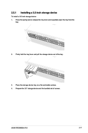
Prepare the 3.5" storage device and the bundled set of the bay. 3. Press the spring lock to release the tray lever and to partially eject the tray from the bay. 2. 2.5.1 Installing a 3.5-inch storage device To install a 3.5-inch storage device: 1. Firmly hold the tray lever and pull the storage device out of screws. Place the storage device tray on a flat and stable surface. 4. ASUS ESC8000A-E12 2-17
Prepare the 3.5" storage device and the bundled set of the bay. 3. Press the spring lock to release the tray lever and to partially eject the tray from the bay. 2. 2.5.1 Installing a 3.5-inch storage device To install a 3.5-inch storage device: 1. Firmly hold the tray lever and pull the storage device out of screws. Place the storage device tray on a flat and stable surface. 4. ASUS ESC8000A-E12 2-17

User Manual
Page 41
Carefully insert the tray and push it with four screws. 4. Place the 2.5" storage device into the tray, then secure it all the way into the storage device bay, then lock the tray lever to 3 of screws. 3. ASUS ESC8000A-E12 2-19 Repeat steps 1 to 4 to remove the drive tray from the chassis. 2. Follow steps 1 to secure the drive bay in place. 5. Prepare the 2.5" storage device and the bundled set of the Installing a 3.5-inch storage device section to install additional 2.5" storage devices. 2.5.2 Installing a 2.5-inch storage device 1.
Carefully insert the tray and push it with four screws. 4. Place the 2.5" storage device into the tray, then secure it all the way into the storage device bay, then lock the tray lever to 3 of screws. 3. ASUS ESC8000A-E12 2-19 Repeat steps 1 to 4 to remove the drive tray from the chassis. 2. Follow steps 1 to secure the drive bay in place. 5. Prepare the 2.5" storage device and the bundled set of the Installing a 3.5-inch storage device section to install additional 2.5" storage devices. 2.5.2 Installing a 2.5-inch storage device 1.
User Manual
Page 43
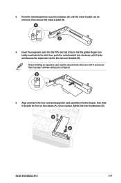
... the expansion card into the slot, then push the metal bracket lock clockwise until the metal bracket can be removed, then remove the metal bracket (B). 4. ASUS ESC8000A-E12 2-21 Push the metal bracket lock counter clockwise (A) until it locks and secures the expansion card to the riser card bracket (B). Before installing an expansion...
... the expansion card into the slot, then push the metal bracket lock clockwise until the metal bracket can be removed, then remove the metal bracket (B). 4. ASUS ESC8000A-E12 2-21 Push the metal bracket lock counter clockwise (A) until it locks and secures the expansion card to the riser card bracket (B). Before installing an expansion...
User Manual
Page 45
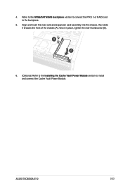
4. Align and insert the riser card and expansion card assembly into the chassis, then slide it towards the front of the chassis (A). ASUS ESC8000A-E12 2-23 Refer to the NVMe/SATA/SAS backplane section to connect the PIKE II or RAID card to install and connect the Cache Vault Power Module. Once in place, tighten the riser thumbscrew (B). 6. (Optional) Refer to the Installing the Cache Vault Power Module section to the backplane. 5.
4. Align and insert the riser card and expansion card assembly into the chassis, then slide it towards the front of the chassis (A). ASUS ESC8000A-E12 2-23 Refer to the NVMe/SATA/SAS backplane section to connect the PIKE II or RAID card to install and connect the Cache Vault Power Module. Once in place, tighten the riser thumbscrew (B). 6. (Optional) Refer to the Installing the Cache Vault Power Module section to the backplane. 5.
User Manual
Page 47
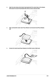
3. Align the screw holes on the Cache Vault bracket with the screw holes on the chassis, then secure the Cache Vault bracket with the two screws removed earlier. 4. Connect the Cache Vault Power Module to the PIKE II card or RAID card. ASUS ESC8000A-E12 2-25 Align and install the Cache Vault Power Module into the Cache Vault Power Module clip. 5.
3. Align the screw holes on the Cache Vault bracket with the screw holes on the chassis, then secure the Cache Vault bracket with the two screws removed earlier. 4. Connect the Cache Vault Power Module to the PIKE II card or RAID card. ASUS ESC8000A-E12 2-25 Align and install the Cache Vault Power Module into the Cache Vault Power Module clip. 5.
User Manual
Page 49
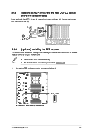
... connector on select models) Insert and push the OCP 3.0 card all the way into the socket board (A), then secure the card with the thumb screw (B). ASUS ESC8000A-E12 2-27 Locate the PFR module connector on your motherboard. • The illustration below is for reference only. • For more information or assistance, please refer...
... connector on select models) Insert and push the OCP 3.0 card all the way into the socket board (A), then secure the card with the thumb screw (B). ASUS ESC8000A-E12 2-27 Locate the PFR module connector on your motherboard. • The illustration below is for reference only. • For more information or assistance, please refer...


