
A7V8X-X User Manual
Page 11
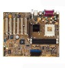
Chapter 1 This chapter gives information about the ASUS A7V8X-X motherboard that came with the system.This chapter includes the motherboard layout, jumper settings, and connector locations. Motherboard Info ASUS A7V8X-X Motherboard 1-1
Chapter 1 This chapter gives information about the ASUS A7V8X-X motherboard that came with the system.This chapter includes the motherboard layout, jumper settings, and connector locations. Motherboard Info ASUS A7V8X-X Motherboard 1-1
A7V8X-X User Manual
Page 12
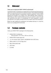
... extra jumper caps User Guide I/O shield 1-2 This motherboard is loaded with the list below. 1.2 Package contents Check your ASUS A7V8X-X package for buying the ASUS® A7V8X-X motherboard! Thank you start installing the motherboard, and hardware devices on it, check the items in your package with the... most advanced technologies to ensure the best user experience and value in (30.5 cm x 24.5 cm) ASUS A7V8X-X series support CD 1 pc. 80-conductor ribbon cable for UltraDMA/66/100/133 IDE drives Ribbon cable for guaranteed consumer satisfaction. Before...
... extra jumper caps User Guide I/O shield 1-2 This motherboard is loaded with the list below. 1.2 Package contents Check your ASUS A7V8X-X package for buying the ASUS® A7V8X-X motherboard! Thank you start installing the motherboard, and hardware devices on it, check the items in your package with the... most advanced technologies to ensure the best user experience and value in (30.5 cm x 24.5 cm) ASUS A7V8X-X series support CD 1 pc. 80-conductor ribbon cable for UltraDMA/66/100/133 IDE drives Ribbon cable for guaranteed consumer satisfaction. Before...

A7V8X-X User Manual
Page 13
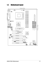
1.3 Motherboard components Before you install the motherboard, learn about its major components and available features to the succeeding pages for the component descriptions. 1 2 3 4 14 13 12 11 15 10 9 16 17 25 24 23 ASUS A7V8X-X Motherboard 22 21 5 6 7 8 18 19 20 1-3 Refer to facilitate the installation and future upgrades.
1.3 Motherboard components Before you install the motherboard, learn about its major components and available features to the succeeding pages for the component descriptions. 1 2 3 4 14 13 12 11 15 10 9 16 17 25 24 23 ASUS A7V8X-X Motherboard 22 21 5 6 7 8 18 19 20 1-3 Refer to facilitate the installation and future upgrades.

A7V8X-X User Manual
Page 15
... available for a PS/2 mouse. 16 Parallel port. This port connects to a Local Area Network (LAN) through a network hub. (on LAN model only) 14 AGP slot. ASUS A7V8X-X Motherboard 1-5 The audio CODEC provides six DAC channels for pointing devices or other devices. 17 RJ-45 port. This Realtek RTL8201BL LAN PHY supports your...
... available for a PS/2 mouse. 16 Parallel port. This port connects to a Local Area Network (LAN) through a network hub. (on LAN model only) 14 AGP slot. ASUS A7V8X-X Motherboard 1-5 The audio CODEC provides six DAC channels for pointing devices or other devices. 17 RJ-45 port. This Realtek RTL8201BL LAN PHY supports your...
A7V8X-X User Manual
Page 17
...:Line Out Below:Mic In AUX CD LAN PHY FP_AUDIO Audio Codec MDC VIA KT400 Chipset Accelerated Graphics Port (AGP) 01 23 45 PCI Slot 1 A7V8X-X PCI Slot 2 PCI Slot 3 PCI Slot 4 PCI Slot 5 ® PCI Slot 6 VIA VT8235 Chipset CR2032 3V Lithium Cell CMOS Power CLRTC Super I/O GAME USBPW56 USB56...
...:Line Out Below:Mic In AUX CD LAN PHY FP_AUDIO Audio Codec MDC VIA KT400 Chipset Accelerated Graphics Port (AGP) 01 23 45 PCI Slot 1 A7V8X-X PCI Slot 2 PCI Slot 3 PCI Slot 4 PCI Slot 5 ® PCI Slot 6 VIA VT8235 Chipset CR2032 3V Lithium Cell CMOS Power CLRTC Super I/O GAME USBPW56 USB56...

A7V8X-X User Manual
Page 19
... to do so may damage the motherboard. Do not overtighten the screws! The edge with external ports goes to the rear part of the chassis ASUS A7V8X-X Motherboard 1-9 Make sure to unplug the power cord before installing or removing the motherboard. 1.7 Motherboard installation Before you place it into the chassis in the...
... to do so may damage the motherboard. Do not overtighten the screws! The edge with external ports goes to the rear part of the chassis ASUS A7V8X-X Motherboard 1-9 Make sure to unplug the power cord before installing or removing the motherboard. 1.7 Motherboard installation Before you place it into the chassis in the...
A7V8X-X User Manual
Page 21
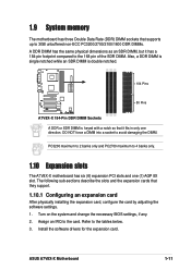
..., but it fits in only one (1) AGP 8X slot. Also, a DDR DIMM is single notched while an SDR DIMM is double notched. 104 Pins A7V8X-X ® 80 Pins A7V8X-X 184-Pin DDR DIMM Sockets A DDR or SDR DIMM is keyed with a notch so that they support. 1.10.1 Configuring an expansion card After... slots and one direction. The following sub-sections describe the slots and the expansion cards that it has a 184-pin footprint compared to the card. ASUS A7V8X-X Motherboard 1-11 Assign an IRQ to the 168-pin of the SDR DIMM. Turn on the system and change the necessary BIOS settings, if any...
..., but it fits in only one (1) AGP 8X slot. Also, a DDR DIMM is single notched while an SDR DIMM is double notched. 104 Pins A7V8X-X ® 80 Pins A7V8X-X 184-Pin DDR DIMM Sockets A DDR or SDR DIMM is keyed with a notch so that they support. 1.10.1 Configuring an expansion card After... slots and one direction. The following sub-sections describe the slots and the expansion cards that it has a 184-pin footprint compared to the card. ASUS A7V8X-X Motherboard 1-11 Assign an IRQ to the 168-pin of the SDR DIMM. Turn on the system and change the necessary BIOS settings, if any...

A7V8X-X User Manual
Page 23
... high core voltage may adjust the CPU VCORE through the BIOS Setup. OVER_VOLT 12 23 Enable Disable (Default) A7V8X-X ® A7V8X-X OVER_VOLT Setting Setting to 2.05V. ASUS A7V8X-X Motherboard 1-13 The total current consumed must NOT exceed the power supply capability (+5VSB) whether under normal condition... the internal USB header that you can provide at least 1A on the motherboard. 1. USBPW12 USBPW34 12 23 A7V8X-X ® +5V (Default) +5VSB USBPW56 12 23 A7V8X-X USB Device Wake Up +5V (Default) +5VSB 2. USB device wake-up (3-pin USBPWR12,USBPWR34,USBPWR56) Set...
... high core voltage may adjust the CPU VCORE through the BIOS Setup. OVER_VOLT 12 23 Enable Disable (Default) A7V8X-X ® A7V8X-X OVER_VOLT Setting Setting to 2.05V. ASUS A7V8X-X Motherboard 1-13 The total current consumed must NOT exceed the power supply capability (+5VSB) whether under normal condition... the internal USB header that you can provide at least 1A on the motherboard. 1. USBPW12 USBPW34 12 23 A7V8X-X ® +5V (Default) +5VSB USBPW56 12 23 A7V8X-X USB Device Wake Up +5V (Default) +5VSB 2. USB device wake-up (3-pin USBPWR12,USBPWR34,USBPWR56) Set...

A7V8X-X User Manual
Page 25
...powering up if the power supply is 230W, or 300W for four additional USB port connectors. USB+6V USB_P6USB_P6+ GND NC A7V8X-X ® USB56 1 USB+5V USB_P5USB_P5+ GND A7V8X-X USB 2.0 Header The USB/GAME module is not included in the future, make sure that your new ATX 12V power ...supply can provide 8A on the +12V lead and at least 1A on the motherboard. 1. ASUS A7V8X-X Motherboard 1-15 1.12 Connectors This section describes and illustrates the connectors on the +5-volt standby lead (+5VSB). ATX power connectors (20-pin ATXPWR)...
...powering up if the power supply is 230W, or 300W for four additional USB port connectors. USB+6V USB_P6USB_P6+ GND NC A7V8X-X ® USB56 1 USB+5V USB_P5USB_P5+ GND A7V8X-X USB 2.0 Header The USB/GAME module is not included in the future, make sure that your new ATX 12V power ...supply can provide 8A on the +12V lead and at least 1A on the motherboard. 1. ASUS A7V8X-X Motherboard 1-15 1.12 Connectors This section describes and illustrates the connectors on the +5-volt standby lead (+5VSB). ATX power connectors (20-pin ATXPWR)...

A7V8X-X User Manual
Page 27
... fan connectors support cooling fans of 350mA (4.2 Watts) or a total of the expansion slots. FLOPPY A7V8X-X PIN 1 ® NOTE: Orient the red markings on the fan manufacturer. CPU_FAN GND +12V Rotation A7V8X-X ® CHA_FAN Rotation +12V GND A7V8X-X 12-Volt Cooling Fan Power Do not forget to connect the fan cables to prevent.... 5. DO NOT place jumper caps on the fan connectors! Floppy disk drive connector (34-1 pin FLOPPY) This connector supports the provided floppy drive ribbon cable. ASUS A7V8X-X Motherboard 1-17
... fan connectors support cooling fans of 350mA (4.2 Watts) or a total of the expansion slots. FLOPPY A7V8X-X PIN 1 ® NOTE: Orient the red markings on the fan manufacturer. CPU_FAN GND +12V Rotation A7V8X-X ® CHA_FAN Rotation +12V GND A7V8X-X 12-Volt Cooling Fan Power Do not forget to connect the fan cables to prevent.... 5. DO NOT place jumper caps on the fan connectors! Floppy disk drive connector (34-1 pin FLOPPY) This connector supports the provided floppy drive ribbon cable. ASUS A7V8X-X Motherboard 1-17
A7V8X-X User Manual
Page 29
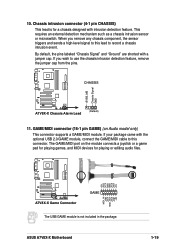
...for playing or editing audio files. +5V J1B2 J1CY GND GND J1CX J1B1 +5V A7V8X-X ® A7V8X-X Game Connector GAME The USB/GAME module is for a chassis designed with a jumper cap. ASUS A7V8X-X Motherboard MIDI_IN J2B2 J2CY MIDI_OUT J2CX J2B1 +5V 1-19 This requires an external detection ... detection feature. Chassis intrusion connector (4-1 pin CHASSIS) This lead is not included in the package. CHASSIS +5VSB_MB Chassis Signal GND A7V8X-X ® A7V8X-X Chassis Alarm Lead (Default) 11. If your package came with the optional USB 2.0/GAME module, connect the GAME/MIDI cable ...
...for playing or editing audio files. +5V J1B2 J1CY GND GND J1CX J1B1 +5V A7V8X-X ® A7V8X-X Game Connector GAME The USB/GAME module is for a chassis designed with a jumper cap. ASUS A7V8X-X Motherboard MIDI_IN J2B2 J2CY MIDI_OUT J2CX J2B1 +5V 1-19 This requires an external detection ... detection feature. Chassis intrusion connector (4-1 pin CHASSIS) This lead is not included in the package. CHASSIS +5VSB_MB Chassis Signal GND A7V8X-X ® A7V8X-X Chassis Alarm Lead (Default) 11. If your package came with the optional USB 2.0/GAME module, connect the GAME/MIDI cable ...
A7V8X-X User Manual
Page 31
BIOS Information ASUS A7V8X-X Motherboard 2-1 Chapter 2 This chapter gives information about the ASUS A7V8X-X Binary Input/Output System (BIOS).This chapter includes updating the BIOS using the ASUS AFLASH BIOS that is bundled with the support CD.
BIOS Information ASUS A7V8X-X Motherboard 2-1 Chapter 2 This chapter gives information about the ASUS A7V8X-X Binary Input/Output System (BIOS).This chapter includes updating the BIOS using the ASUS AFLASH BIOS that is bundled with the support CD.
A7V8X-X User Manual
Page 32
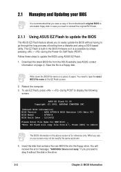
... from A:\, Press [ESC] to go through the long process of paper. Reboot the computer. 3. ASUS EZ Flash V1.00 Copyright (C) 2002, ASUSTeK COMPUTER INC. [Onboard BIOS Information] BIOS Version : ASUS A7V8X-X BIOS Revision 1001 Beta 003 BIOS Model : A7V8X-X BIOS Built Date : 12/14/02 Please Enter File Name for reference only. Device not...
... from A:\, Press [ESC] to go through the long process of paper. Reboot the computer. 3. ASUS EZ Flash V1.00 Copyright (C) 2002, ASUSTeK COMPUTER INC. [Onboard BIOS Information] BIOS Version : ASUS A7V8X-X BIOS Revision 1001 Beta 003 BIOS Model : A7V8X-X BIOS Built Date : 12/14/02 Please Enter File Name for reference only. Device not...
A7V8X-X User Manual
Page 33
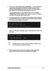
... updating the BIOS. Flash Memory: SST 49LF004 1. At the query prompt, type Y to remove the message, then type in File] BIOS Version: A7V8X-X Boot Block WARNING! Doing so may cause system boot failure. 8. Press . 6. EZ Flash will automatically access drive A to update the BIOS (Y/N)?... _ 7. File not found , the following prompts appear if you downloaded from the ASUS website, then press . When found ." Update Boot Block area (Y/N)? _ (Y/N)? _ DO NOT shutdown or reset the system while updating the BIOS boot...
... updating the BIOS. Flash Memory: SST 49LF004 1. At the query prompt, type Y to remove the message, then type in File] BIOS Version: A7V8X-X Boot Block WARNING! Doing so may cause system boot failure. 8. Press . 6. EZ Flash will automatically access drive A to update the BIOS (Y/N)?... _ 7. File not found , the following prompts appear if you downloaded from the ASUS website, then press . When found ." Update Boot Block area (Y/N)? _ (Y/N)? _ DO NOT shutdown or reset the system while updating the BIOS boot...
A7V8X-X User Manual
Page 35
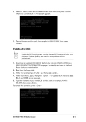
...BIOS Including Boot Block and ESCD screen appears. 5. XX.XXX, then press . Download an updated ASUS BIOS file from the Main menu and press . Select 1. At the "A:\" prompt, type AFLASH and then press . 4. ASUS A7V8X-X Motherboard 2-5 The Save Current BIOS To File screen appears. 6. Type the filename of your problems..., A:\XXX- At the Main Menu, type 2 then press . Save Current BIOS to File from the Internet (WWW or FTP) (see ASUS CONTACT INFORMATION on page x for details) and save to the boot floppy disk you are sure that the new BIOS revision will solve your new...
...BIOS Including Boot Block and ESCD screen appears. 5. XX.XXX, then press . Download an updated ASUS BIOS file from the Main menu and press . Select 1. At the "A:\" prompt, type AFLASH and then press . 4. ASUS A7V8X-X Motherboard 2-5 The Save Current BIOS To File screen appears. 6. Type the filename of your problems..., A:\XXX- At the Main Menu, type 2 then press . Save Current BIOS to File from the Internet (WWW or FTP) (see ASUS CONTACT INFORMATION on page x for details) and save to the boot floppy disk you are sure that the new BIOS revision will solve your new...
A7V8X-X User Manual
Page 37
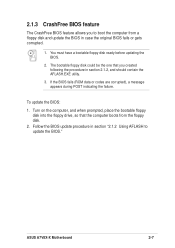
... drive, so that you to update the BIOS." If the BIOS fails (ROM data or codes are corrupted), a message appears during POST indicating the failure. ASUS A7V8X-X Motherboard 2-7
... drive, so that you to update the BIOS." If the BIOS fails (ROM data or codes are corrupted), a message appears during POST indicating the failure. ASUS A7V8X-X Motherboard 2-7
A7V8X-X User Manual
Page 39
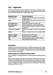
ASUS A7V8X-X Motherboard 2-9 The keys in the legend bar with their corresponding functions. The General Help screen lists the legend keys and their corresponding functions. To exit ...
ASUS A7V8X-X Motherboard 2-9 The keys in the legend bar with their corresponding functions. The General Help screen lists the legend keys and their corresponding functions. To exit ...
A7V8X-X User Manual
Page 41
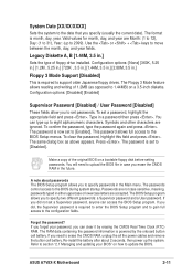
... cell battery. Press . You will need to 2099). The RAM data containing the password information is now set a password, highlight the appropriate field and press . ASUS A7V8X-X Motherboard 2-11 Use the or + keys to the BIOS during system startup. To set to the configuration fields. Passwords are accepted. Forgot the password? If...
... cell battery. Press . You will need to 2099). The RAM data containing the password information is now set a password, highlight the appropriate field and press . ASUS A7V8X-X Motherboard 2-11 Use the or + keys to the BIOS during system startup. To set to the configuration fields. Passwords are accepted. Forgot the password? If...

A7V8X-X User Manual
Page 43
... this field, set the Type field to [User Type HDD] and the Translation Method field to [Manual]. for LS-120 compatible floppy disk drives [ZIP] - ASUS A7V8X-X Motherboard 2-13 for cylinders, heads, or sectors. When Logical Block Addressing (LBA) is enabled, the 28-bit addressing of cylinders. To make changes to this...
... this field, set the Type field to [User Type HDD] and the Translation Method field to [Manual]. for LS-120 compatible floppy disk drives [ZIP] - ASUS A7V8X-X Motherboard 2-13 for cylinders, heads, or sectors. When Logical Block Addressing (LBA) is enabled, the 28-bit addressing of cylinders. To make changes to this...

A7V8X-X User Manual
Page 45
... second. CPU VCore Setting [Auto] The [Manual] setting allows you keep the default setting [Auto] to allow the system to the CPU (see next item). ASUS A7V8X-X Motherboard 2-15 Keyboard Auto-Repeat Rate [12/Sec] This controls the speed at which the system registers repeated keystrokes. Configuration options: [6/Sec] [8/Sec] [10/Sec...
... second. CPU VCore Setting [Auto] The [Manual] setting allows you keep the default setting [Auto] to allow the system to the CPU (see next item). ASUS A7V8X-X Motherboard 2-15 Keyboard Auto-Repeat Rate [12/Sec] This controls the speed at which the system registers repeated keystrokes. Configuration options: [6/Sec] [8/Sec] [10/Sec...


