
A7V8X-X User Manual
Page 1
Motherboard A7V8X-X User Guide
Motherboard A7V8X-X User Guide
A7V8X-X User Manual
Page 3
Features Contents Notices v Safety information vi About this guide vii ASUS contact information viii A7V8X-X specifications summary ix Chapter 1: Product introduction 1.1 Welcome 1-2 1.2 Package contents 1-2 1.3 Motherboard components 1-3 1.3.1 Core specifications 1-4 1.4 Special Features 1-6 1.4.1 Product highlights 1-6 1.5 Motherboard layout 1-7 1.6 Before you proceed 1-8 1.7 Motherboard installation 1-9 1.7.1 Placement direction 1-9 1.7.2 Screw holes 1-9 1.8 Central Processing Unit (CPU 1-10 1.8.1 Installing the CPU 1-10 1.9 System memory 1-11 1.10...
Features Contents Notices v Safety information vi About this guide vii ASUS contact information viii A7V8X-X specifications summary ix Chapter 1: Product introduction 1.1 Welcome 1-2 1.2 Package contents 1-2 1.3 Motherboard components 1-3 1.3.1 Core specifications 1-4 1.4 Special Features 1-6 1.4.1 Product highlights 1-6 1.5 Motherboard layout 1-7 1.6 Before you proceed 1-8 1.7 Motherboard installation 1-9 1.7.1 Placement direction 1-9 1.7.2 Screw holes 1-9 1.8 Central Processing Unit (CPU 1-10 1.8.1 Installing the CPU 1-10 1.9 System memory 1-11 1.10...

A7V8X-X User Manual
Page 6
... sure that your power supply is broken, do not try to fix it , carefully read all the manuals that all power cables from the motherboard, ensure that came with the product, contact a qualified service technician or your retailer. If you detect any area where it may become wet.... • Place the product on it by yourself. Operation safety • Before installing the motherboard and adding devices on a stable surface. • If you encounter technical problems with the package. • Before using the product, make sure all...
... sure that your power supply is broken, do not try to fix it , carefully read all the manuals that all power cables from the motherboard, ensure that came with the product, contact a qualified service technician or your retailer. If you detect any area where it may become wet.... • Place the product on it by yourself. Operation safety • Before installing the motherboard and adding devices on a stable surface. • If you encounter technical problems with the package. • Before using the product, make sure all...

A7V8X-X User Manual
Page 11
Motherboard Info ASUS A7V8X-X Motherboard 1-1 Chapter 1 This chapter gives information about the ASUS A7V8X-X motherboard that came with the system.This chapter includes the motherboard layout, jumper settings, and connector locations.
Motherboard Info ASUS A7V8X-X Motherboard 1-1 Chapter 1 This chapter gives information about the ASUS A7V8X-X motherboard that came with the system.This chapter includes the motherboard layout, jumper settings, and connector locations.
A7V8X-X User Manual
Page 12
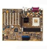
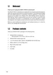
... hardware devices on it, check the items in your ASUS A7V8X-X package for the following items. ASUS A7V8X-X motherboard ATX form factor: 12 in x 9.6 in a motherboard. For future upgrades or system reconfiguration, this chapter provides technical information about the motherboard. Unique ASUS features such as ASUS C.O.P., ASUS C.P.R., ASUS EZFlash, ASUS JumperFree, ASUS MyLogo, ASUS CrashFree BIOS and more are included to deliver the maximum...
... hardware devices on it, check the items in your ASUS A7V8X-X package for the following items. ASUS A7V8X-X motherboard ATX form factor: 12 in x 9.6 in a motherboard. For future upgrades or system reconfiguration, this chapter provides technical information about the motherboard. Unique ASUS features such as ASUS C.O.P., ASUS C.P.R., ASUS EZFlash, ASUS JumperFree, ASUS MyLogo, ASUS CrashFree BIOS and more are included to deliver the maximum...

A7V8X-X User Manual
Page 13
Refer to facilitate the installation and future upgrades. 1.3 Motherboard components Before you install the motherboard, learn about its major components and available features to the succeeding pages for the component descriptions. 1 2 3 4 14 13 12 11 15 10 9 16 17 25 24 23 ASUS A7V8X-X Motherboard 22 21 5 6 7 8 18 19 20 1-3
Refer to facilitate the installation and future upgrades. 1.3 Motherboard components Before you install the motherboard, learn about its major components and available features to the succeeding pages for the component descriptions. 1 2 3 4 14 13 12 11 15 10 9 16 17 25 24 23 ASUS A7V8X-X Motherboard 22 21 5 6 7 8 18 19 20 1-3
A7V8X-X User Manual
Page 14
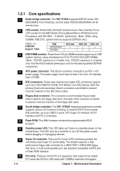
Visit the ASUS website [www.asus.com] for a 360K/720K/1.44M/2.88M floppy disk drive, a multi-mode parallel port, two standard compatible UARTs and a Flash ROM interface. 11 PCI slots. This ... to 4 banks only. This connector accommodates the provided ribbon cable for the AMD Barton/Thoroughbred/Athlon XP/Athlon/Duron Processors, with 133MB/s maximum throughput. 1-4 Chapter 1: Motherboard Information 1.3.1 Core specifications 1 North bridge controller. Socket 462 (Socket A) surface mount, Zero Insertion Force (ZIF) socket for the floppy disk drive. This 2Mb firmware contains...
Visit the ASUS website [www.asus.com] for a 360K/720K/1.44M/2.88M floppy disk drive, a multi-mode parallel port, two standard compatible UARTs and a Flash ROM interface. 11 PCI slots. This ... to 4 banks only. This connector accommodates the provided ribbon cable for the AMD Barton/Thoroughbred/Athlon XP/Athlon/Duron Processors, with 133MB/s maximum throughput. 1-4 Chapter 1: Motherboard Information 1.3.1 Core specifications 1 North bridge controller. Socket 462 (Socket A) surface mount, Zero Insertion Force (ZIF) socket for the floppy disk drive. This 2Mb firmware contains...

A7V8X-X User Manual
Page 15
.... 25 PS/2 keyboard port. 12 Audio CODEC . These two 4-pin Universal Serial Bus (USB) ports are available for connecting USB 2.0 devices. 22 USB 2.0 ports 1 and 2. ASUS A7V8X-X Motherboard 1-5 In 6-channel mode, the function of this jack becomes Bass/ Center. (on LAN models only) 18 Line In jack. These two 4-pin Universal Serial Bus...
.... 25 PS/2 keyboard port. 12 Audio CODEC . These two 4-pin Universal Serial Bus (USB) ports are available for connecting USB 2.0 devices. 22 USB 2.0 ports 1 and 2. ASUS A7V8X-X Motherboard 1-5 In 6-channel mode, the function of this jack becomes Bass/ Center. (on LAN models only) 18 Line In jack. These two 4-pin Universal Serial Bus...
A7V8X-X User Manual
Page 16
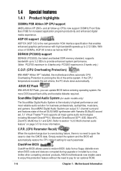
...will automatically restore the CPU default setting for business professionals, audiophiles, musicians, and gamers. Unlike other competing vendors' products, ASUS motherboards now enable users to enjoy this protection feature without the need to open the case to 4 banks only. 1.4 Special...Side Bus (FSB) for an optional ROM. 1-6 Chapter 1: Motherboard Information PC3200 maximum to 2 banks only.) C.O.P. (CPU Overheating Protection): With AMD® Athlon XP™ installed, the motherboard offers automatic CPU Overheating Protection to pay for increased application program productivity...
...will automatically restore the CPU default setting for business professionals, audiophiles, musicians, and gamers. Unlike other competing vendors' products, ASUS motherboards now enable users to enjoy this protection feature without the need to open the case to 4 banks only. 1.4 Special...Side Bus (FSB) for an optional ROM. 1-6 Chapter 1: Motherboard Information PC3200 maximum to 2 banks only.) C.O.P. (CPU Overheating Protection): With AMD® Athlon XP™ installed, the motherboard offers automatic CPU Overheating Protection to pay for increased application program productivity...
A7V8X-X User Manual
Page 17
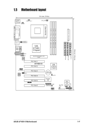
1.5 Motherboard layout PS/2KBMS T: Mouse B: Keyboard KBPWR OVER_VOLT SPDIF1 24.4cm (9.6in) CPU_FAN ATX Power Connector Socket 462 DDR DIMM1 (64/72 bit, 184-pin module) ... Chipset Accelerated Graphics Port (AGP) 01 23 45 PCI Slot 1 A7V8X-X PCI Slot 2 PCI Slot 3 PCI Slot 4 PCI Slot 5 ® PCI Slot 6 VIA VT8235 Chipset CR2032 3V Lithium Cell CMOS Power CLRTC Super I/O GAME USBPW56 USB56 IDE_LED SB_PWR 2Mbit Firmware Hub CHASSIS CHA_FAN PANEL PRI_IDE SEC_IDE FLOPPY 30.5cm (12.0in) ASUS A7V8X-X Motherboard 1-7
1.5 Motherboard layout PS/2KBMS T: Mouse B: Keyboard KBPWR OVER_VOLT SPDIF1 24.4cm (9.6in) CPU_FAN ATX Power Connector Socket 462 DDR DIMM1 (64/72 bit, 184-pin module) ... Chipset Accelerated Graphics Port (AGP) 01 23 45 PCI Slot 1 A7V8X-X PCI Slot 2 PCI Slot 3 PCI Slot 4 PCI Slot 5 ® PCI Slot 6 VIA VT8235 Chipset CR2032 3V Lithium Cell CMOS Power CLRTC Super I/O GAME USBPW56 USB56 IDE_LED SB_PWR 2Mbit Firmware Hub CHASSIS CHA_FAN PANEL PRI_IDE SEC_IDE FLOPPY 30.5cm (12.0in) ASUS A7V8X-X Motherboard 1-7
A7V8X-X User Manual
Page 18
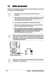
...green LED (SB_PWR) indicates that the system is ON, in sleep mode, or in any component, place it on them due to the motherboard, peripherals, and/or components. Unplug the power cord from the power supply. Before you should shut down the system and unplug the power ...cable before touching any motherboard settings. 1. A7V8X-X ® A7V8X-X Onboard LED SB_PWR ON Standby Power OFF Powered Off Install only 1.5V AGP cards on this motherboard to prevent damage to avoid touching the ICs on a grounded antistatic pad or in...
...green LED (SB_PWR) indicates that the system is ON, in sleep mode, or in any component, place it on them due to the motherboard, peripherals, and/or components. Unplug the power cord from the power supply. Before you should shut down the system and unplug the power ...cable before touching any motherboard settings. 1. A7V8X-X ® A7V8X-X Onboard LED SB_PWR ON Standby Power OFF Powered Off Install only 1.5V AGP cards on this motherboard to prevent damage to avoid touching the ICs on a grounded antistatic pad or in...

A7V8X-X User Manual
Page 19
... rear part of your chassis to ensure that the motherboard fits into it into the holes indicated by circles to secure the motherboard to unplug the power cord before installing or removing the motherboard. Place this side towards the rear of the chassis ASUS A7V8X-X Motherboard 1-9 The motherboard uses the ATX form factor that you physical injury...
... rear part of your chassis to ensure that the motherboard fits into it into the holes indicated by circles to secure the motherboard to unplug the power cord before installing or removing the motherboard. Place this side towards the rear of the chassis ASUS A7V8X-X Motherboard 1-9 The motherboard uses the ATX form factor that you physical injury...
A7V8X-X User Manual
Page 20
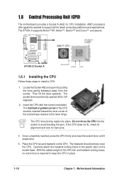
... force the CPU into place. The heatsink should drop easily into the socket to keep the CPU in place 1-10 Chapter 1: Motherboard Information With the added weight of the socket base nearest to the plastic clips on the CPU. Insert the CPU with the correct...by pulling the lever gently sideways away from the socket. 1.8 Central Processing Unit (CPU) The motherboard provides a Socket A (462) for bent pins. 4. AMD processors offer gigahertz speeds to install a CPU: 1. The A7V8X-X supports AthlonTM XP, AthlonTM, Barton™ and DuronTM processors. Then lift the lever upwards....
... force the CPU into place. The heatsink should drop easily into the socket to keep the CPU in place 1-10 Chapter 1: Motherboard Information With the added weight of the socket base nearest to the plastic clips on the CPU. Insert the CPU with the correct...by pulling the lever gently sideways away from the socket. 1.8 Central Processing Unit (CPU) The motherboard provides a Socket A (462) for bent pins. 4. AMD processors offer gigahertz speeds to install a CPU: 1. The A7V8X-X supports AthlonTM XP, AthlonTM, Barton™ and DuronTM processors. Then lift the lever upwards....
A7V8X-X User Manual
Page 21
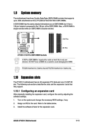
...1.10 Expansion slots The A7V8X-X motherboard has six (6) expansion PCI slots and one direction. DO NOT force a DIMM into a socket to the card. Turn on the system and change the necessary BIOS settings, if any. 2. Assign an IRQ to avoid damaging the DIMM. ASUS A7V8X-X Motherboard 1-11 Refer to the... tables below. 3. 1.9 System memory The motherboard has three Double Data Rate (DDR) DIMM sockets that supports up to 3GB unbuffered non-ECC PC3200...
...1.10 Expansion slots The A7V8X-X motherboard has six (6) expansion PCI slots and one direction. DO NOT force a DIMM into a socket to the card. Turn on the system and change the necessary BIOS settings, if any. 2. Assign an IRQ to avoid damaging the DIMM. ASUS A7V8X-X Motherboard 1-11 Refer to the... tables below. 3. 1.9 System memory The motherboard has three Double Data Rate (DDR) DIMM sockets that supports up to 3GB unbuffered non-ECC PC3200...
A7V8X-X User Manual
Page 22
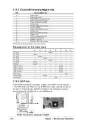
... an Accelerated Graphics Port (AGP) slot that they fit the AGP slot on your motherboard. shared - - - - - - - - shared - - - - - - - A7V8X-X 1-12 ® A7V8X-X Accelerated Graphics Port (AGP ) Chapter 1: Motherboard Information IRQ assignments for this motherboard PCI slot 1 PCI slot 2 PCI slot 3 PCI slot 4 PCI slot 5 PCI slot 6 AGP slot USB 1.1 UHCI 1 USB 1.1 UHCI 2 USB 1.1 UHCI 3 USB 2.0 EHCI...
... an Accelerated Graphics Port (AGP) slot that they fit the AGP slot on your motherboard. shared - - - - - - - - shared - - - - - - - A7V8X-X 1-12 ® A7V8X-X Accelerated Graphics Port (AGP ) Chapter 1: Motherboard Information IRQ assignments for this motherboard PCI slot 1 PCI slot 2 PCI slot 3 PCI slot 4 PCI slot 5 PCI slot 6 AGP slot USB 1.1 UHCI 1 USB 1.1 UHCI 2 USB 1.1 UHCI 3 USB 2.0 EHCI...

A7V8X-X User Manual
Page 23
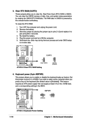
... these jumpers to +5V to wake up . USB device wake-up the computer from S3 sleep mode (no power to +1.85V. ASUS A7V8X-X Motherboard 1-13 You may cause permanent damage to support this feature. Set to +5VSB to wake up (3-pin USBPWR12,USBPWR34,USBPWR56) Set these... that you can provide at least 1A on the motherboard. 1. USBPW12 USBPW34 12 23 A7V8X-X ® +5V (Default) +5VSB USBPW56 12 23 A7V8X-X USB Device Wake Up +5V (Default) +5VSB 2. OVER_VOLT 12 23 Enable Disable (Default) A7V8X-X ® A7V8X-X OVER_VOLT Setting Setting to the front USB ports. It...
... these jumpers to +5V to wake up . USB device wake-up the computer from S3 sleep mode (no power to +1.85V. ASUS A7V8X-X Motherboard 1-13 You may cause permanent damage to support this feature. Set to +5VSB to wake up (3-pin USBPWR12,USBPWR34,USBPWR56) Set these... that you can provide at least 1A on the motherboard. 1. USBPW12 USBPW34 12 23 A7V8X-X ® +5V (Default) +5VSB USBPW56 12 23 A7V8X-X USB Device Wake Up +5V (Default) +5VSB 2. OVER_VOLT 12 23 Enable Disable (Default) A7V8X-X ® A7V8X-X OVER_VOLT Setting Setting to the front USB ports. It...
A7V8X-X User Manual
Page 24
... wake-up the computer when you to re-enter data. Turn OFF the computer and unplug the power cord. 2. A7V8X-X KBPWR 12 23 +5V (Default) +5VSB ® A7V8X-X Keyboard Power Setting 1-14 Chapter 1: Motherboard Information Re-install the battery. 5. 3. Hold down the key during the boot process and enter BIOS setup to clear...
... wake-up the computer when you to re-enter data. Turn OFF the computer and unplug the power cord. 2. A7V8X-X KBPWR 12 23 +5V (Default) +5VSB ® A7V8X-X Keyboard Power Setting 1-14 Chapter 1: Motherboard Information Re-install the battery. 5. 3. Hold down the key during the boot process and enter BIOS setup to clear...

A7V8X-X User Manual
Page 25
... the +5-volt standby lead (+5VSB). USB+6V USB_P6USB_P6+ GND NC A7V8X-X ® USB56 1 USB+5V USB_P5USB_P5+ GND A7V8X-X USB 2.0 Header The USB/GAME module is not included in the chassis. USB headers (10-1 pin USB56) If the USB 2.0 port connectors on the motherboard. 1. The minimum recommended wattage is inadequate. 2. The system may become..., two USB headers (blue headers) are designed to an ATX 12V power supply. The plugs from the power supply are available for a fully configured system. ASUS A7V8X-X Motherboard 1-15
... the +5-volt standby lead (+5VSB). USB+6V USB_P6USB_P6+ GND NC A7V8X-X ® USB56 1 USB+5V USB_P5USB_P5+ GND A7V8X-X USB 2.0 Header The USB/GAME module is not included in the chassis. USB headers (10-1 pin USB56) If the USB 2.0 port connectors on the motherboard. 1. The minimum recommended wattage is inadequate. 2. The system may become..., two USB headers (blue headers) are designed to an ATX 12V power supply. The plugs from the power supply are available for a fully configured system. ASUS A7V8X-X Motherboard 1-15
A7V8X-X User Manual
Page 26
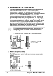
...non-UltraDMA/133/100/66 devices to PIN 1. MODEM_IN AC97_SYNC AC97_SDIN1 GND AC97_BITCLK A7V8X-X 1-16 ® A7V8X-X MDC Header GND +3VSB AC97_RST# AC97_SDOUT MDC Chapter 1: Motherboard Information BIOS supports specific device bootup. You may configure two hard disks to... the UltraDMA/133/100/66 master device. IDE connectors (40-1 pin PRI_IDE, SEC_IDE) This connector supports the provided UltraDMA/133/100/66 IDE hard disk ribbon cable. MDC header (10-1 pin MDC) This ASUS...
...non-UltraDMA/133/100/66 devices to PIN 1. MODEM_IN AC97_SYNC AC97_SDIN1 GND AC97_BITCLK A7V8X-X 1-16 ® A7V8X-X MDC Header GND +3VSB AC97_RST# AC97_SDOUT MDC Chapter 1: Motherboard Information BIOS supports specific device bootup. You may configure two hard disks to... the UltraDMA/133/100/66 master device. IDE connectors (40-1 pin PRI_IDE, SEC_IDE) This connector supports the provided UltraDMA/133/100/66 IDE hard disk ribbon cable. MDC header (10-1 pin MDC) This ASUS...

A7V8X-X User Manual
Page 27
... wire to go across the onboard heat sinks instead of 1A (12W) at +12V. The fan wiring and plug may damage the motherboard components. ASUS A7V8X-X Motherboard 1-17 5. A7V8X-X Floppy Disk Drive Connector 6. FLOPPY A7V8X-X PIN 1 ® NOTE: Orient the red markings on the fan connectors! Orient the fans so that the heat sink fins allow...
... wire to go across the onboard heat sinks instead of 1A (12W) at +12V. The fan wiring and plug may damage the motherboard components. ASUS A7V8X-X Motherboard 1-17 5. A7V8X-X Floppy Disk Drive Connector 6. FLOPPY A7V8X-X PIN 1 ® NOTE: Orient the red markings on the fan connectors! Orient the fans so that the heat sink fins allow...


