
A7V8X-X User Manual
Page 1
Motherboard A7V8X-X User Guide
Motherboard A7V8X-X User Guide
A7V8X-X User Manual
Page 3
Features Contents Notices v Safety information vi About this guide vii ASUS contact information viii A7V8X-X specifications summary ix Chapter 1: Product introduction 1.1 Welcome 1-2 1.2 Package contents 1-2 1.3 Motherboard components 1-3 1.3.1 Core specifications 1-4 1.4 Special Features 1-6 1.4.1 Product highlights 1-6 1.5 Motherboard layout 1-7 1.6 Before you proceed 1-8 1.7 Motherboard installation 1-9 1.7.1 Placement direction 1-9 1.7.2 Screw holes 1-9 1.8 Central Processing Unit (CPU 1-10 1.8.1 Installing the CPU 1-10 1.9 System memory 1-11 1.10...
Features Contents Notices v Safety information vi About this guide vii ASUS contact information viii A7V8X-X specifications summary ix Chapter 1: Product introduction 1.1 Welcome 1-2 1.2 Package contents 1-2 1.3 Motherboard components 1-3 1.3.1 Core specifications 1-4 1.4 Special Features 1-6 1.4.1 Product highlights 1-6 1.5 Motherboard layout 1-7 1.6 Before you proceed 1-8 1.7 Motherboard installation 1-9 1.7.1 Placement direction 1-9 1.7.2 Screw holes 1-9 1.8 Central Processing Unit (CPU 1-10 1.8.1 Installing the CPU 1-10 1.9 System memory 1-11 1.10...

A7V8X-X User Manual
Page 6
... possible, disconnect all power cables from the existing system before you add a device. • Before connecting or removing signal cables from the motherboard, ensure that the power cables for the devices are unplugged before using , contact your local power company. • If the power supply ...all power cables are unplugged. • Seek professional assistance before the signal cables are connected. Operation safety • Before installing the motherboard and adding devices on it, carefully read all the manuals that your power supply is broken, do not try to the correct voltage ...
... possible, disconnect all power cables from the existing system before you add a device. • Before connecting or removing signal cables from the motherboard, ensure that the power cables for the devices are unplugged before using , contact your local power company. • If the power supply ...all power cables are unplugged. • Seek professional assistance before the signal cables are connected. Operation safety • Before installing the motherboard and adding devices on it, carefully read all the manuals that your power supply is broken, do not try to the correct voltage ...

A7V8X-X User Manual
Page 11
Motherboard Info ASUS A7V8X-X Motherboard 1-1 Chapter 1 This chapter gives information about the ASUS A7V8X-X motherboard that came with the system.This chapter includes the motherboard layout, jumper settings, and connector locations.
Motherboard Info ASUS A7V8X-X Motherboard 1-1 Chapter 1 This chapter gives information about the ASUS A7V8X-X motherboard that came with the system.This chapter includes the motherboard layout, jumper settings, and connector locations.
A7V8X-X User Manual
Page 12
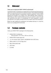
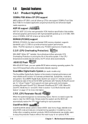
.../100/133 IDE drives Ribbon cable for the following items. ASUS A7V8X-X motherboard ATX form factor: 12 in x 9.6 in a motherboard. This motherboard is loaded with value-added features for guaranteed consumer satisfaction. Before you for socket A processors. Unique ASUS features such as ASUS C.O.P., ASUS C.P.R., ASUS EZFlash, ASUS JumperFree, ASUS MyLogo, ASUS CrashFree BIOS and more are included to deliver the maximum performance...
.../100/133 IDE drives Ribbon cable for the following items. ASUS A7V8X-X motherboard ATX form factor: 12 in x 9.6 in a motherboard. This motherboard is loaded with value-added features for guaranteed consumer satisfaction. Before you for socket A processors. Unique ASUS features such as ASUS C.O.P., ASUS C.P.R., ASUS EZFlash, ASUS JumperFree, ASUS MyLogo, ASUS CrashFree BIOS and more are included to deliver the maximum performance...

A7V8X-X User Manual
Page 13
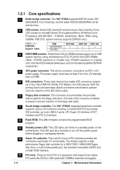
Refer to facilitate the installation and future upgrades. 1.3 Motherboard components Before you install the motherboard, learn about its major components and available features to the succeeding pages for the component descriptions. 1 2 3 4 14 13 12 11 15 10 9 16 17 25 24 23 ASUS A7V8X-X Motherboard 22 21 5 6 7 8 18 19 20 1-3
Refer to facilitate the installation and future upgrades. 1.3 Motherboard components Before you install the motherboard, learn about its major components and available features to the succeeding pages for the component descriptions. 1 2 3 4 14 13 12 11 15 10 9 16 17 25 24 23 ASUS A7V8X-X Motherboard 22 21 5 6 7 8 18 19 20 1-3
A7V8X-X User Manual
Page 14
... are slotted to six USB 2.0 ports, LPC Super I /O functionality. Visit the ASUS website [www.asus.com] for the AMD Barton/Thoroughbred/Athlon XP/Athlon/Duron Processors, with 133MB/s maximum throughput. 1-4 Chapter 1: Motherboard Information The power supply must have at least 1A on the motherboard. One side of the IDE ribbon cable. 6 Floppy disk connector.
... are slotted to six USB 2.0 ports, LPC Super I /O functionality. Visit the ASUS website [www.asus.com] for the AMD Barton/Thoroughbred/Athlon XP/Athlon/Duron Processors, with 133MB/s maximum throughput. 1-4 Chapter 1: Motherboard Information The power supply must have at least 1A on the motherboard. One side of the IDE ribbon cable. 6 Floppy disk connector.

A7V8X-X User Manual
Page 15
... this jack becomes Rear Speaker Out. (on audio models only) The functions of this jack becomes Bass/ Center. (on LAN model only) 14 AGP slot. ASUS A7V8X-X Motherboard 1-5 The audio CODEC provides six DAC channels for 3D graphical applications. 15 PS/2 mouse port.
... this jack becomes Rear Speaker Out. (on audio models only) The functions of this jack becomes Bass/ Center. (on LAN model only) 14 AGP slot. ASUS A7V8X-X Motherboard 1-5 The audio CODEC provides six DAC channels for 3D graphical applications. 15 PS/2 mouse port.
A7V8X-X User Manual
Page 16
... Flash With ASUS EZ Flash, you can output 5.1 channel surround and features state-of 533Mhz, AGP 8X is the industry's highest performance and most reliable audio solution for an optional ROM. 1-6 Chapter 1: Motherboard Information Refer to prolong the life of the entire system. ...productivity and enhanced digital media experience. CrashFree BIOS CrashFree BIOS allows users to 4 banks only. Unlike other competing vendors' products, ASUS motherboards now enable users to enjoy this protection feature without the need to open the case to pay for business professionals, audiophiles, ...
... Flash With ASUS EZ Flash, you can output 5.1 channel surround and features state-of 533Mhz, AGP 8X is the industry's highest performance and most reliable audio solution for an optional ROM. 1-6 Chapter 1: Motherboard Information Refer to prolong the life of the entire system. ...productivity and enhanced digital media experience. CrashFree BIOS CrashFree BIOS allows users to 4 banks only. Unlike other competing vendors' products, ASUS motherboards now enable users to enjoy this protection feature without the need to open the case to pay for business professionals, audiophiles, ...
A7V8X-X User Manual
Page 17
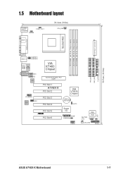
1.5 Motherboard layout PS/2KBMS T: Mouse B: Keyboard KBPWR OVER_VOLT SPDIF1 24.4cm (9.6in) CPU_FAN ATX Power Connector Socket 462 DDR DIMM1 (64/72 bit, 184-pin module) ... Chipset Accelerated Graphics Port (AGP) 01 23 45 PCI Slot 1 A7V8X-X PCI Slot 2 PCI Slot 3 PCI Slot 4 PCI Slot 5 ® PCI Slot 6 VIA VT8235 Chipset CR2032 3V Lithium Cell CMOS Power CLRTC Super I/O GAME USBPW56 USB56 IDE_LED SB_PWR 2Mbit Firmware Hub CHASSIS CHA_FAN PANEL PRI_IDE SEC_IDE FLOPPY 30.5cm (12.0in) ASUS A7V8X-X Motherboard 1-7
1.5 Motherboard layout PS/2KBMS T: Mouse B: Keyboard KBPWR OVER_VOLT SPDIF1 24.4cm (9.6in) CPU_FAN ATX Power Connector Socket 462 DDR DIMM1 (64/72 bit, 184-pin module) ... Chipset Accelerated Graphics Port (AGP) 01 23 45 PCI Slot 1 A7V8X-X PCI Slot 2 PCI Slot 3 PCI Slot 4 PCI Slot 5 ® PCI Slot 6 VIA VT8235 Chipset CR2032 3V Lithium Cell CMOS Power CLRTC Super I/O GAME USBPW56 USB56 IDE_LED SB_PWR 2Mbit Firmware Hub CHASSIS CHA_FAN PANEL PRI_IDE SEC_IDE FLOPPY 30.5cm (12.0in) ASUS A7V8X-X Motherboard 1-7
A7V8X-X User Manual
Page 18
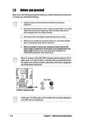
... case, before handling components to avoid damaging them . 4. Hold components by the edges to avoid touching the ICs on this motherboard to prevent damage to your AGP card or motherboard. 1-8 Chapter 1: Motherboard Information A7V8X-X ® A7V8X-X Onboard LED SB_PWR ON Standby Power OFF Powered Off Install only 1.5V AGP cards on them due to the...
... case, before handling components to avoid damaging them . 4. Hold components by the edges to avoid touching the ICs on this motherboard to prevent damage to your AGP card or motherboard. 1-8 Chapter 1: Motherboard Information A7V8X-X ® A7V8X-X Onboard LED SB_PWR ON Standby Power OFF Powered Off Install only 1.5V AGP cards on them due to the...

A7V8X-X User Manual
Page 19
... power cord before installing or removing the motherboard. Do not overtighten the screws! The motherboard uses the ATX form factor that you install the motherboard, study the configuration of the chassis ASUS A7V8X-X Motherboard 1-9 Doing so may cause you physical injury and damage motherboard components. 1.7.1 Placement direction When installing the motherboard, make sure that measures 12 inches x 9.6 inches...
... power cord before installing or removing the motherboard. Do not overtighten the screws! The motherboard uses the ATX form factor that you install the motherboard, study the configuration of the chassis ASUS A7V8X-X Motherboard 1-9 Doing so may cause you physical injury and damage motherboard components. 1.7.1 Placement direction When installing the motherboard, make sure that measures 12 inches x 9.6 inches...
A7V8X-X User Manual
Page 20
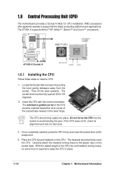
1.8 Central Processing Unit (CPU) The motherboard provides a Socket A (462) for bent pins. 4. A7V8X-X ® A7V8X-X Socket A AMD™ CPU CPU NOTCH TO INNER CORNER CPU NOTCH LEVER LOCK 1.8.1 Installing the CPU Follow these steps to support all the latest computing .... Do not force the CPU into place. With the added weight of the socket base nearest to keep the CPU in place 1-10 Chapter 1: Motherboard Information The A7V8X-X supports AthlonTM XP, AthlonTM, Barton™ and DuronTM processors. The socket lever must be fully opened (90 to the plastic clips on the CPU...
1.8 Central Processing Unit (CPU) The motherboard provides a Socket A (462) for bent pins. 4. A7V8X-X ® A7V8X-X Socket A AMD™ CPU CPU NOTCH TO INNER CORNER CPU NOTCH LEVER LOCK 1.8.1 Installing the CPU Follow these steps to support all the latest computing .... Do not force the CPU into place. With the added weight of the socket base nearest to keep the CPU in place 1-10 Chapter 1: Motherboard Information The A7V8X-X supports AthlonTM XP, AthlonTM, Barton™ and DuronTM processors. The socket lever must be fully opened (90 to the plastic clips on the CPU...
A7V8X-X User Manual
Page 21
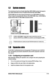
...an SDR DIMM, but it fits in only one (1) AGP 8X slot. Assign an IRQ to avoid damaging the DIMM. ASUS A7V8X-X Motherboard 1-11 DO NOT force a DIMM into a socket to the card. Turn on the system and change the necessary BIOS ...if any. 2. Also, a DDR DIMM is single notched while an SDR DIMM is double notched. 104 Pins A7V8X-X ® 80 Pins A7V8X-X 184-Pin DDR DIMM Sockets A DDR or SDR DIMM is keyed with a notch so that they support.... 2 banks only and PC2700 maximum to 4 banks only. 1.10 Expansion slots The A7V8X-X motherboard has six (6) expansion PCI slots and one direction.
...an SDR DIMM, but it fits in only one (1) AGP 8X slot. Assign an IRQ to avoid damaging the DIMM. ASUS A7V8X-X Motherboard 1-11 DO NOT force a DIMM into a socket to the card. Turn on the system and change the necessary BIOS ...if any. 2. Also, a DDR DIMM is single notched while an SDR DIMM is double notched. 104 Pins A7V8X-X ® 80 Pins A7V8X-X 184-Pin DDR DIMM Sockets A DDR or SDR DIMM is keyed with a notch so that they support.... 2 banks only and PC2700 maximum to 4 banks only. 1.10 Expansion slots The A7V8X-X motherboard has six (6) expansion PCI slots and one direction.
A7V8X-X User Manual
Page 22
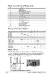
...- - - - shared - - - - - -- - - - - - When you buy an AGP card, make sure that you ask for this motherboard PCI slot 1 PCI slot 2 PCI slot 3 PCI slot 4 PCI slot 5 PCI slot 6 AGP slot USB 1.1 UHCI 1 USB 1.1 UHCI 2 USB ...LAN Onboard IDE A B C D E F GH - - - shared - - - - -- - - A7V8X-X 1-12 ® A7V8X-X Accelerated Graphics Port (AGP ) Chapter 1: Motherboard Information shared - - - - - - - used - - - Note the notches on your motherboard. shared - - -- shared - - - - - - - IRQ assignments for one with +1.5V specification....
...- - - - shared - - - - - -- - - - - - When you buy an AGP card, make sure that you ask for this motherboard PCI slot 1 PCI slot 2 PCI slot 3 PCI slot 4 PCI slot 5 PCI slot 6 AGP slot USB 1.1 UHCI 1 USB 1.1 UHCI 2 USB ...LAN Onboard IDE A B C D E F GH - - - shared - - - - -- - - A7V8X-X 1-12 ® A7V8X-X Accelerated Graphics Port (AGP ) Chapter 1: Motherboard Information shared - - - - - - - used - - - Note the notches on your motherboard. shared - - -- shared - - - - - - - IRQ assignments for one with +1.5V specification....

A7V8X-X User Manual
Page 23
...up the computer from S3 sleep mode (no power to +1.85V. USBPW12 USBPW34 12 23 A7V8X-X ® +5V (Default) +5VSB USBPW56 12 23 A7V8X-X USB Device Wake Up +5V (Default) +5VSB 2. ASUS A7V8X-X Motherboard 1-13 USB device wake-up (3-pin USBPWR12,USBPWR34,USBPWR56) Set these jumpers are set ... USB devices. The USBPWR12 and USBPWR34 jumpers are for the internal USB header that you can provide at least 1A on the motherboard. 1. The total current consumed must NOT exceed the power supply capability (+5VSB) whether under normal condition or in reduced power mode...
...up the computer from S3 sleep mode (no power to +1.85V. USBPW12 USBPW34 12 23 A7V8X-X ® +5V (Default) +5VSB USBPW56 12 23 A7V8X-X USB Device Wake Up +5V (Default) +5VSB 2. ASUS A7V8X-X Motherboard 1-13 USB device wake-up (3-pin USBPWR12,USBPWR34,USBPWR56) Set these jumpers are set ... USB devices. The USBPWR12 and USBPWR34 jumpers are for the internal USB header that you can provide at least 1A on the motherboard. 1. The total current consumed must NOT exceed the power supply capability (+5VSB) whether under normal condition or in reduced power mode...
A7V8X-X User Manual
Page 24
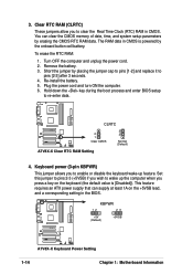
...; 2 1 Clear CMOS 3 2 Normal (Default) A7V8X-X Clear RTC RAM Setting 4. A7V8X-X KBPWR 12 23 +5V (Default) +5VSB ® A7V8X-X Keyboard Power Setting 1-14 Chapter 1: Motherboard Information Turn OFF the computer and unplug the power cord. 2. The RAM data in CMOS is [Disabled]). Remove the battery. 3. Short the jumper by erasing ...
...; 2 1 Clear CMOS 3 2 Normal (Default) A7V8X-X Clear RTC RAM Setting 4. A7V8X-X KBPWR 12 23 +5V (Default) +5VSB ® A7V8X-X Keyboard Power Setting 1-14 Chapter 1: Motherboard Information Turn OFF the computer and unplug the power cord. 2. The RAM data in CMOS is [Disabled]). Remove the battery. 3. Short the jumper by erasing ...

A7V8X-X User Manual
Page 25
Find the proper orientation and push down firmly until the connectors completely fit. ASUS A7V8X-X Motherboard 1-15 ATXPWR A7V8X-X ® +3.3VDC -12.0VDC COM PS_ON# COM COM COM -5.0VDC +5.0VDC +5.0VDC A7V8X-X ATX Power Connectors +3.3VDC +3.3VDC COM +5.0VDC COM +5.0VDC COM PWR_OK +5VSB +12.0VDC If you ... at least 1A on the +5-volt standby lead (+5VSB). USB headers (10-1 pin USB56) If the USB 2.0 port connectors on the motherboard. 1. The system may become unstable and may experience difficulty powering up if the power supply is not included in only one orientation. Connect ...
Find the proper orientation and push down firmly until the connectors completely fit. ASUS A7V8X-X Motherboard 1-15 ATXPWR A7V8X-X ® +3.3VDC -12.0VDC COM PS_ON# COM COM COM -5.0VDC +5.0VDC +5.0VDC A7V8X-X ATX Power Connectors +3.3VDC +3.3VDC COM +5.0VDC COM +5.0VDC COM PWR_OK +5VSB +12.0VDC If you ... at least 1A on the +5-volt standby lead (+5VSB). USB headers (10-1 pin USB56) If the USB 2.0 port connectors on the motherboard. 1. The system may become unstable and may experience difficulty powering up if the power supply is not included in only one orientation. Connect ...
A7V8X-X User Manual
Page 26
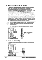
... 80-conductor IDE cable. You may configure two hard disks to the UltraDMA/133/100/66 master device. PRI_IDE SEC_IDE ® A7V8X-X IDE Connectors PIN 1 4. Pin 20 on each IDE connector is recommended that you have more than two UltraDMA/133/100/66... (10-1 pin MDC) This ASUS proprietary modem header accomodates an optional modem module. If you install two hard disks, you connect the cables. MODEM_IN AC97_SYNC AC97_SDIN1 GND AC97_BITCLK A7V8X-X 1-16 ® A7V8X-X MDC Header GND +3VSB AC97_RST# AC97_SDOUT MDC Chapter 1: Motherboard Information Refer to PIN 1. one...
... 80-conductor IDE cable. You may configure two hard disks to the UltraDMA/133/100/66 master device. PRI_IDE SEC_IDE ® A7V8X-X IDE Connectors PIN 1 4. Pin 20 on each IDE connector is recommended that you have more than two UltraDMA/133/100/66... (10-1 pin MDC) This ASUS proprietary modem header accomodates an optional modem module. If you install two hard disks, you connect the cables. MODEM_IN AC97_SYNC AC97_SDIN1 GND AC97_BITCLK A7V8X-X 1-16 ® A7V8X-X MDC Header GND +3VSB AC97_RST# AC97_SDOUT MDC Chapter 1: Motherboard Information Refer to PIN 1. one...

A7V8X-X User Manual
Page 27
The fan wiring and plug may damage the motherboard components. Lack of the expansion slots. CPU_FAN GND +12V Rotation A7V8X-X ® CHA_FAN Rotation +12V GND A7V8X-X 12-Volt Cooling Fan Power Do not forget to connect the fan cables to prevent incorrect insertion when ... drive. (Pin 5 is removed to the fan connectors. These are not jumpers! DO NOT place jumper caps on the fan manufacturer. ASUS A7V8X-X Motherboard 1-17 A7V8X-X Floppy Disk Drive Connector 6. CPU and Chassis Fan Connectors (3-pin CPU_FAN, CHA_FAN) The two fan connectors support cooling fans of 350mA (4.2...
The fan wiring and plug may damage the motherboard components. Lack of the expansion slots. CPU_FAN GND +12V Rotation A7V8X-X ® CHA_FAN Rotation +12V GND A7V8X-X 12-Volt Cooling Fan Power Do not forget to connect the fan cables to prevent incorrect insertion when ... drive. (Pin 5 is removed to the fan connectors. These are not jumpers! DO NOT place jumper caps on the fan manufacturer. ASUS A7V8X-X Motherboard 1-17 A7V8X-X Floppy Disk Drive Connector 6. CPU and Chassis Fan Connectors (3-pin CPU_FAN, CHA_FAN) The two fan connectors support cooling fans of 350mA (4.2...


