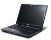
Extensa 4620Z / 4220 User's Guide EN
Page 4
...; Do not place this product through cabinet slots as they may result in a fire or electric shock. Also, make sure that could be blocked or covered. Make sure the power outlet is a safety feature. Contact your dealer or local power company. • Do not allow anything to prevent battery leakage, do...
Extensa 4620Z / 4220 User's Guide EN
Page 5
... disassemble the battery. The battery can be charged and Product servicing Do not attempt to service this product yourself, as opening or removing covers may expose you come into the product • the product was exposed to rain or water • the product has been dropped ... work by other risks. If the battery leaks and you to dangerous voltage points or other nearby electrical devices that are covered by the operating instructions, since improper adjustment of this product from unexpected noise produced by a qualified technician to restore the product to ...
Extensa 4620Z / 4220 User's Guide EN
Page 45
25 Indicators The computer has serveral easy-to-read status indicators. English The front panel indicators are visible even when the computer cover is closed up when Num Lock is charging. 2. Indicates the computer's power status. Fully charged: The light shows green when in AC mode. Wireless LAN ...
Extensa 4620Z / 4220 User's Guide EN
Page 66
...program. Our worldwide network of time a call . A list of available, authorized service centers is in the flap located inside the front cover of mind when traveling. This passport contains all you security and peace of the ITW passport. With your computer, write them down as they...beeps). Always have your ITW passport on your problems efficiently. English 46 To start the recovery process: 1 Restart the system. 2 While the Acer logo is showing, press + at the same time to enter the recovery process. 3 Refer to the onscreen instructions to provide the following ...
Extensa 4620Z / 4220 User's Guide EN
Page 71
... you are taking the computer to a client's office or a different building, you may choose to shut down the computer. 4 Close the display cover. 5 Disconnect the cord from your office desk to secure the computer. then press and release the power button. You can put the computer in... open the display; Preparing the computer Before moving within the building. then press and release the power button. Then close and latch the display cover to disconnect your computer from external accessories: 1 Save any open files. 2 Remove any media, floppy disks or compact disks from the desktop Follow...
Extensa 4620Z / 4220 User's Guide EN
Page 72
... outlet, reduce the drain on the battery by putting the computer in Sleep mode for a period of the computer. Press + or close the display cover whenever you may enter Hibernation mode after being in Sleep mode. Failure to turn the computer back on , the computer has entered Sleep mode. Note.... To resume, open the display (if closed), then press and release the power button. Caution: Avoid packing items next to your office to the top cover of time. Taking the computer home When you : • AC adapter and power cord • The printed User's Guide If the power indicator is ...
Extensa 4620Z / 4220 User's Guide EN
Page 81
... lift up and remove the memory cover. 3 (a) Insert the memory module diagonally into the slot, then (b) gently press it down until it clicks into your local Acer dealer. However, if you encounter configuration problems, you do not need to run it with the screw. 5 Reinstall the battery pack, ..., and you may need to run this utility. BIOS utility The BIOS utility is a hardware configuration program built into place. 4 Replace the memory cover and secure it . Then turn the computer over to install memory: 1 Turn off the computer, unplug the AC adapter (if connected) and remove...
TravelMate 4320/4720 and Extensa 4220/4620 Service Guide
Page 6
... with all technical information relating to extend the functionality of this generic service guide. For ACER-AUTHORIZED SERVICE PROVIDERS, your regional web or channel. Preface Before using this information and the... will NOT be noted in the FRU list of a machine (e.g. add-on your Acer office may have decided to the BASIC CONFIGURATION decided for repair and service of customer ...machines. To better fit local market requirements and enhance product competitiveness, your regional Acer office to those given in the printed Service Guide. You MUST use the list provided...
TravelMate 4320/4720 and Extensa 4220/4620 Service Guide
Page 8
...Modules Disassembly Flowchart 50 Removing the Battery Pack 51 Removing the SD Dummy Card 51 Removing the Express Dummy Card 52 Removing the Lower Cover 53 Removing the DIMM 53 Removing the WLAN Board Modules 54 Removing the Hard Disk Drive Module 55 Removing the Optical Drive Module 57...59 Main Unit Disassembly Flowchart 59 Removing the Fan Module 60 Removing the CPU Heatsink Module 61 Removing the CPU 62 Removing the Middle Cover 63 Removing the Keyboard 64 Removing the LCD Module 67 Separating the Upper Case from the Lower Case 70 Removing the Touchpad Board ...
TravelMate 4320/4720 and Extensa 4220/4620 Service Guide
Page 18
... Lights up . Indicators The computer has four easy-to-read status indicators: Icon Function Description The front panel indicators are visible even when the computer cover is active. Icon Function HDD Num lock Cap lock Power Battery Bluetooth Description Indicates when the hard disc or optical drive is closed up when...
TravelMate 4320/4720 and Extensa 4220/4620 Service Guide
Page 60
... remove the keyboard, then disassemble the inside assembly frame in that need to be removed during servicing. TURN OFF POWER AND PERIPHERALS Ax4 Bx1 LOWER COVER UNPLUG POWER CABLES Ex1 OPTICAL DISK DRIVE MODULE Cx2 WLAN BOARD DIMM MODULES HARD DISK DRIVE MODULE Fx1 OPTICAL LOCKER BRACKET OPTICAL DISK DRIVE HDD...
TravelMate 4320/4720 and Extensa 4220/4620 Service Guide
Page 63
...-cm Torque 1.6 kgf-cm Removing the DIMM 1. Remove the lower cover from the lower case. See "Removing the Battery Pack" on the lower cover. Use a plastic screw driver to pry open the lower cover. 7. See "Removing the Lower Cover" on page 51. 2. Removing the Lower Cover 1. Step 1~4 Size (Quantity) M2 x L4 (4) 5. Step Size (Quantity) 5 M2...
TravelMate 4320/4720 and Extensa 4220/4620 Service Guide
Page 64
Removing the WLAN Board Modules 1. See "Removing the Lower Cover" on both sides of the DIMM socket to release the DIMM. 6. Remove the mylar tape from the mic cable. 54 Chapter 3 Push out the latches on page 53. 5. See "Removing the Battery Pack" on the other board. Do the same on page 51. 2. See "Removing the Express Dummy Card" on page 51. 3. See "Removing the SD Dummy Card" on page 52. 4. 5. Remove the DIMM module. 7.
TravelMate 4320/4720 and Extensa 4220/4620 Service Guide
Page 65
.... 2. Step 1~2 Size (Quantity) M2 x L3 (2) 8. Color Silver Torque 1.6 kgf-cm NOTE: When attaching the antennas back to release the WLAN board. See "Removing the Lower Cover" on the WLAN board to the WLAN board, make sure the cable are routed properly. Remove the two screws (C) on page 53. Detach the WLAN...
TravelMate 4320/4720 and Extensa 4220/4620 Service Guide
Page 67
Color Silver Torque 1.6 kgf-cm Removing the Optical Drive Module 1. See "Removing the SD Dummy Card" on page 52. 4. Step 1 Size (Quantity) M2 x L6 (1) Color Black Torque 1.6 kgf-cm Chapter 3 57 7. Step 7 Size (Quantity) M3 x L4 (2) 8. See "Removing the Express Dummy Card" on page 51. 3. See "Removing the Battery Pack" on page 53. 5. See "Removing the Lower Cover" on page 51. 2. Remove the two screws (D) on the bottom side of the unit. Turn the base unit over, then remove the screw (E) on the HDD bracket. Remove the bracket as shown.
TravelMate 4320/4720 and Extensa 4220/4620 Service Guide
Page 69
Main Unit Disassembly Process Main Unit Disassembly Flowchart MAIN UNIT DISASSEMBLY MAIN UNIT Fx2 FAN Ax5 CPU HEATSINK MODULE CPU Hx1 LED INDICATORS BOARD MIDDLE COVER Cx2 KEYBOARD Dx4 LCD MODULE Ax1, Gx11 UPPER CASE Cx4 TOUCHPAD BRACKET ASSEMBLY TOUCHPAD BOARD Cx2 DAUGHTER BOARD Ax1 MAIN BOARD Cx2 MODEM BOARD Cx2 FINGERPRINT BOARD BLUETOOTH BOARD Ax2 SPEAKER MODULES LOWER CASE Chapter 3 59
TravelMate 4320/4720 and Extensa 4220/4620 Service Guide
Page 70
Detach the heatsink cable. See "Removing the Express Dummy Card" on the fan. 60 Chapter 3 Part No. 86.00G64.720 86.9A552.3R0 86.00E33.736 86.00F22.722 86.00C07.220 86.00C07.220 6. Detach the tin foil tape on page 52. 4. See "Removing the Battery Pack" on page 51. 3. Screw List A C D F G H Screw M2 x L4 M2 x L3 (Black) M2.5 x L6 M2 x L2.5 M2 x L3 (Silver) M2 x L3 Removing the Fan Module 1. See "Removing the SD Dummy Card" on page 51. 2. See "Removing the Lower Cover" on page 53. 5.
TravelMate 4320/4720 and Extensa 4220/4620 Service Guide
Page 71
... 3 Color Silver Torque 1.6 kgf-cm 61 Color Silver Torque 1.6 kgf-cm Removing the CPU Heatsink Module 1. Step 1-2 Size (Quantity) M2 x L2.5 (2) 8. See "Removing the Lower Cover" on page 51. 2. Remove the screws (F) securing the fan to the main unit. See "Removing the Battery Pack" on page 53. 5. 7. See "Removing the Fan...
TravelMate 4320/4720 and Extensa 4220/4620 Service Guide
Page 72
See "Removing the Lower Cover" on page 51. 2. See "Removing the Battery Pack" on page 53. 5. See "Removing the Fan Module" on page 61. 62 Chapter 3 Remove the heatsink. See "Removing the CPU Heatsink Module" on page 60. 6. 7. Carefully pull the heatsink out of the edge of the main unit. 8. Removing the CPU 1. See "Removing the Express Dummy Card" on page 51. 3. See "Removing the SD Dummy Card" on page 52. 4.
TravelMate 4320/4720 and Extensa 4220/4620 Service Guide
Page 73
... the CPU with PIN 1 at the corner as shown. NOTE: When installing the CPU, make sure to facilitate the easy removal of the middle cover. Removing the Middle Cover 1. See "Removing the CPU Heatsink Module" on page 53. 5. Using a flat screwdriver, turn the CPU socket latch counter-clockwise to release the CPU..., then remove the CPU. See "Removing the Lower Cover" on page 61. 7. See "Removing the SD Dummy Card" on page 60. 6. See "Removing the Fan Module" on page 51. 3.