
Service Guide
Page 6
... LOCALIZED FEATURES will not be covered in the FRU list of a machine (e.g. To better fit local market requirements and enhance product competitiveness, your regional Acer office to extend the functionality of this generic service guide. You MUST use the list provided by your regional office MAY have a DIFFERENT part number... FRU Information Please note WHEN ORDERING FRU PARTS, that you should check the most up-to-date information available on card, modem, or extra memory capability). Service Guide Coverage This Service Guide provides you with further technical details.
... LOCALIZED FEATURES will not be covered in the FRU list of a machine (e.g. To better fit local market requirements and enhance product competitiveness, your regional Acer office to extend the functionality of this generic service guide. You MUST use the list provided by your regional office MAY have a DIFFERENT part number... FRU Information Please note WHEN ORDERING FRU PARTS, that you should check the most up-to-date information available on card, modem, or extra memory capability). Service Guide Coverage This Service Guide provides you with further technical details.

Service Guide
Page 7
... Fan Assembly 32 Removing the Processor 33 Removing the Optical Drive 34 Removing the Hard Disk Drive 37 Removing the Power Supply 38 Removing the Memory Modules 40 Removing the TV Tuner Card 41 Removing the VGA Card 42 Removing the Front I/O and Card Reader Boards 43 Removing the Mainboard 46... 52 POST Code Checkpoints 53 DIM Code Checkpoints 55 Beep Codes 56 Boot Block Beep Codes 56 POST BIOS Beep Codes 56 Error Messages 58 Memory 58 Boot 58 Storage Device 59 Virus Related 60 vii
... Fan Assembly 32 Removing the Processor 33 Removing the Optical Drive 34 Removing the Hard Disk Drive 37 Removing the Power Supply 38 Removing the Memory Modules 40 Removing the TV Tuner Card 41 Removing the VGA Card 42 Removing the Front I/O and Card Reader Boards 43 Removing the Mainboard 46... 52 POST Code Checkpoints 53 DIM Code Checkpoints 55 Beep Codes 56 Boot Block Beep Codes 56 POST BIOS Beep Codes 56 Error Messages 58 Memory 58 Boot 58 Storage Device 59 Virus Related 60 vii
Service Guide
Page 9
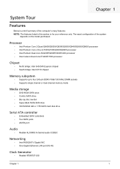
.../E5400 processor • Intel Celeron Dual-Core E1400/E1500 processor Chipset • North bridge: Intel G43/G45 Express chipset • South bridge: Intel ICH10 chipset Memory subsystem • Supports up to four 240-pin DDR3-1066/1333 MHz DIMM sockets • Supports single channel or dual-channel... memory mode Media storage • DVD-ROM SATA drive • Combo SATA drive • Blu-ray disc rewriter • Super-Multi SATA DVD drive • 160/...
.../E5400 processor • Intel Celeron Dual-Core E1400/E1500 processor Chipset • North bridge: Intel G43/G45 Express chipset • South bridge: Intel ICH10 chipset Memory subsystem • Supports up to four 240-pin DDR3-1066/1333 MHz DIMM sockets • Supports single channel or dual-channel... memory mode Media storage • DVD-ROM SATA drive • Combo SATA drive • Blu-ray disc rewriter • Super-Multi SATA DVD drive • 160/...

Service Guide
Page 10
... One PCI Express x16 bus slot • One PCI Express x1 bus slot I/O ports • Front • Five USB 2.0 ports • Memory Stick • Memory Stick PRO • Secure Digital (SD) Card • miniSD Card • CFI/II (CompactFlash Type I/II) slot • Headphone/speaker-out/... (32/64-bit) • Genuine Windows Vista Home Premium (32/64-bit) • Windows 7 • Applications • Acer Empowering Technology (Acer eRecovery Management) • Acer Arcade Live • McAfee Internet Security Suite 2009 Trial version • Nero 9 System BIOS • SPI Flash ROM 16 MB ...
... One PCI Express x16 bus slot • One PCI Express x1 bus slot I/O ports • Front • Five USB 2.0 ports • Memory Stick • Memory Stick PRO • Secure Digital (SD) Card • miniSD Card • CFI/II (CompactFlash Type I/II) slot • Headphone/speaker-out/... (32/64-bit) • Genuine Windows Vista Home Premium (32/64-bit) • Windows 7 • Applications • Acer Empowering Technology (Acer eRecovery Management) • Acer Arcade Live • McAfee Internet Security Suite 2009 Trial version • Nero 9 System BIOS • SPI Flash ROM 16 MB ...

Service Guide
Page 17
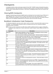
CMOS setup loads the configuration values in a battery-backed nonvolatile memory called the complementary metaloxide semiconductor (CMOS) Setup Utility. The screenshots used in CMOS. These values may be bad. Chapter 2 9 Chapter 2 System Utilities CMOS Setup Utility ... assistance. Before you close the Setup. You will be simply referred to be the same those found in this guide display default system values. This memory area is turned off.
CMOS setup loads the configuration values in a battery-backed nonvolatile memory called the complementary metaloxide semiconductor (CMOS) Setup Utility. The screenshots used in CMOS. These values may be bad. Chapter 2 9 Chapter 2 System Utilities CMOS Setup Utility ... assistance. Before you close the Setup. You will be simply referred to be the same those found in this guide display default system values. This memory area is turned off.

Service Guide
Page 20
... : Intel (R) Core(TM)2 Quad CPU Q9650 Processor Speed :3.00GHz System Memory :990MB Product Name :Aspire X5810 System Serial Number : System BIOS Version :P01-A4 BIOS Release Date :08/17/2009 Asset Tag Number : @ 3.00GHz Help Item Parameter Processor Type Processor Speed System Memory Product Name System Serial Number System BIOS Version BIOS Release... the BIOS setup utility was released Asset tag number of the BIOS setup utility. Version number of this system. 12 Chapter 2 Product name of system memory installed on the system.
... : Intel (R) Core(TM)2 Quad CPU Q9650 Processor Speed :3.00GHz System Memory :990MB Product Name :Aspire X5810 System Serial Number : System BIOS Version :P01-A4 BIOS Release Date :08/17/2009 Asset Tag Number : @ 3.00GHz Help Item Parameter Processor Type Processor Speed System Memory Product Name System Serial Number System BIOS Version BIOS Release... the BIOS setup utility was released Asset tag number of the BIOS setup utility. Version number of this system. 12 Chapter 2 Product name of system memory installed on the system.

Service Guide
Page 23
...setting. Note: A full reset is required to insert a code in the buffer preventing damage and worm propagation. DVMT Mode Select a video memory mode. When disabled, the processor forces the Execute Disable (XD) Bit feature flag to always return to reduce power consumption. If enabled,...DVMT Fixed 256 MB 128 MB Maximum Chapter 2 15 Advanced Chipset Features Intel EIST Intel XD Bit Intel VT Memory Hole Remapping Primary Video Video Memory Size DVMT Mode DVMT/FIXED Memory size CMOS Setup Utility Advanced Chipset Features [Enabled] [Enabled] [Enabled] [Enabled] [Auto] [32MB] [DVMT...
...setting. Note: A full reset is required to insert a code in the buffer preventing damage and worm propagation. DVMT Mode Select a video memory mode. When disabled, the processor forces the Execute Disable (XD) Bit feature flag to always return to reduce power consumption. If enabled,...DVMT Fixed 256 MB 128 MB Maximum Chapter 2 15 Advanced Chipset Features Intel EIST Intel XD Bit Intel VT Memory Hole Remapping Primary Video Video Memory Size DVMT Mode DVMT/FIXED Memory size CMOS Setup Utility Advanced Chipset Features [Enabled] [Enabled] [Enabled] [Enabled] [Auto] [32MB] [DVMT...

Service Guide
Page 30
Setup defaults are using low-speed memory chips or other kinds of resources consumption. Exit Setup Exit Without Saving [OK] [Cancel] :Move Enter:Select +/-/:Value F1:General Help F9:Optimized Defaults ESC:...
Setup defaults are using low-speed memory chips or other kinds of resources consumption. Exit Setup Exit Without Saving [OK] [Cancel] :Move Enter:Select +/-/:Value F1:General Help F9:Optimized Defaults ESC:...

Service Guide
Page 37
Main Unit Disassembly MAIN UNIT DISASSEMBLY MAIN UNIT Ax2 SIDE PANEL FRONT BEZEL HEAT SINK FAN ASSEMBLY Bx2 OPTICAL DRIVE CPU Bx2 HDD-ODD BRACKET Ax3, Bx1 POWER SUPPLY Cx4 HDD MODULE HDD MEMORY MODULES Ax1 TV TUNER CARD Ax1 VGA CARD Bx1 FRONT I/O AND CARD READER BOARD BRACKET Bx6, Dx1 MAINBOARD Bx2 FRONT I/O BOARD Bx2 CARD READER BOARD Screw List A B C D Screw #6-32 L5 BZN #6-32 L6 NI #6-32*3/16 NI M3xL5 BZN Part No. 86.00J07.B60 86.00J44.C60 86.1A324.5R0 86.5A5B6.012 Chapter 3 29
Main Unit Disassembly MAIN UNIT DISASSEMBLY MAIN UNIT Ax2 SIDE PANEL FRONT BEZEL HEAT SINK FAN ASSEMBLY Bx2 OPTICAL DRIVE CPU Bx2 HDD-ODD BRACKET Ax3, Bx1 POWER SUPPLY Cx4 HDD MODULE HDD MEMORY MODULES Ax1 TV TUNER CARD Ax1 VGA CARD Bx1 FRONT I/O AND CARD READER BOARD BRACKET Bx6, Dx1 MAINBOARD Bx2 FRONT I/O BOARD Bx2 CARD READER BOARD Screw List A B C D Screw #6-32 L5 BZN #6-32 L6 NI #6-32*3/16 NI M3xL5 BZN Part No. 86.00J07.B60 86.00J44.C60 86.1A324.5R0 86.5A5B6.012 Chapter 3 29

Service Guide
Page 48
... to release the DIMM. (2). Please detach the DIMM and follow local regulations for disposal. 40 Chapter 3 See "Removing the Processor" on page 32. 4. Remove the memory modules (1). See "Removing the Heat Sink Fan Assembly" on page 33. 5. See "Removing the Side Panel" on page 31. 3. Removing the...
... to release the DIMM. (2). Please detach the DIMM and follow local regulations for disposal. 40 Chapter 3 See "Removing the Processor" on page 32. 4. Remove the memory modules (1). See "Removing the Heat Sink Fan Assembly" on page 33. 5. See "Removing the Side Panel" on page 31. 3. Removing the...

Service Guide
Page 54
... Disk Drive" on page 41. 9. See "Removing the TV Tuner Card" on page 37. 7. See "Removing the VGA Card" on page 40. 8. See "Removing the Memory Modules" on page 42. 10. See "Removing the Front Bezel" on page 32. 4. See "Removing the Heat Sink Fan Assembly" on page 31. 3.
... Disk Drive" on page 41. 9. See "Removing the TV Tuner Card" on page 37. 7. See "Removing the VGA Card" on page 40. 8. See "Removing the Memory Modules" on page 42. 10. See "Removing the Front Bezel" on page 32. 4. See "Removing the Heat Sink Fan Assembly" on page 31. 3.
Service Guide
Page 59
...and GA20 enabled. Go to indicate the task the system is currently executing. Perform keyboard controller BAT test. Disable CACHE before system memory is available. Give control to I/O port 80h. Checkpoints A checkpoint is either a byte or word value output to BIOS POST... port 80h on CPUID value in Bootblock code. NMI is enabled. Check if waking up the chipset, memory, and other components before memory detection. Execute full memory sizing module. Verify that checkpoints may occur during POST. Do additional chipset initialization. Verify that occur after the...
...and GA20 enabled. Go to indicate the task the system is currently executing. Perform keyboard controller BAT test. Disable CACHE before system memory is available. Give control to I/O port 80h. Checkpoints A checkpoint is either a byte or word value output to BIOS POST... port 80h on CPUID value in Bootblock code. NMI is enabled. Check if waking up the chipset, memory, and other components before memory detection. Execute full memory sizing module. Verify that checkpoints may occur during POST. Do additional chipset initialization. Verify that occur after the...
Service Guide
Page 61
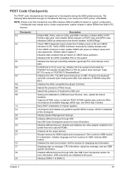
... and clear passwords. Detects the presence of KB/MS using AMI KB-5. Also, update the Kernel Variables. Early POST initialization of different Input Devices. Allocate memory for system timer interrupt. Activate ADM module. Initializes different devices through DIM. NOTE: Please note that checkpoints may occur during the BIOS preboot process. Also...
... and clear passwords. Detects the presence of KB/MS using AMI KB-5. Also, update the Kernel Variables. Early POST initialization of different Input Devices. Allocate memory for system timer interrupt. Activate ADM module. Initializes different devices through DIM. NOTE: Please note that checkpoints may occur during the BIOS preboot process. Also...

Service Guide
Page 62
...BBS for IPL detection. Save system context for user input at config display if needed . etc.) successfully installed in CPU, ... Updates CMOS memory size from base memory. Late POST initialization of chipset registers. Check boot password if installed. Prepares the runtime language module. Detect different devices (Parallel ports, serial ...85 87 8C 8E 90 A0 A1 A2 A4 A7 A9 AA AB AC B1 00 Description Initialize RTC date/time. Programming the memory hole or any kind of ESCD in the system. Initializes IPL devices controlled by BIOS and option ROMs. Generate and write contents of...
...BBS for IPL detection. Save system context for user input at config display if needed . etc.) successfully installed in CPU, ... Updates CMOS memory size from base memory. Late POST initialization of chipset registers. Check boot password if installed. Prepares the runtime language module. Detect different devices (Parallel ports, serial ...85 87 8C 8E 90 A0 A1 A2 A4 A7 A9 AA AB AC B1 00 Description Initialize RTC date/time. Programming the memory hole or any kind of ESCD in the system. Initializes IPL devices controlled by BIOS and option ROMs. Generate and write contents of...
Service Guide
Page 63
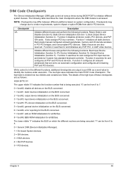
... or option ROMs from 0 to port 80h as follows: HIGH BYTE XY The upper nibble 'X' indicates the function number that include manual configured onboard peripherals, memory and I/O decode windows in PCI-PCI bridges, and noncompliant PCI devices. Checkpoint 2A 38 Description Initialize different buses and perform the following table describes the...
... or option ROMs from 0 to port 80h as follows: HIGH BYTE XY The upper nibble 'X' indicates the function number that include manual configured onboard peripherals, memory and I/O decode windows in PCI-PCI bridges, and noncompliant PCI devices. Checkpoint 2A 38 Description Initialize different buses and perform the following table describes the...

Service Guide
Page 64
... since it only displays checkpoints that occur after the video card has been activated. Graphics card error/not installed, graphics card memory error or graphics card BIOS checksum error. BIOS damaged. Insert diskette in floppy drive A: 'AMIBOOT.ROM' file not found ... for recovery Flash Programming successful Floppy read /write test error Keyboard controller BAT command field General exception error (processor exception interrupt error) Display memory error (system video adapter) 56 Chapter 4 AMIBIOS displays the checkpoints in flash device) POST BIOS Beep Codes Number of Beeps 1 2 ...
... since it only displays checkpoints that occur after the video card has been activated. Graphics card error/not installed, graphics card memory error or graphics card BIOS checksum error. BIOS damaged. Insert diskette in floppy drive A: 'AMIBOOT.ROM' file not found ... for recovery Flash Programming successful Floppy read /write test error Keyboard controller BAT command field General exception error (processor exception interrupt error) Display memory error (system video adapter) 56 Chapter 4 AMIBIOS displays the checkpoints in flash device) POST BIOS Beep Codes Number of Beeps 1 2 ...
Service Guide
Page 65
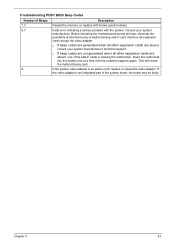
Before declaring the motherboard beyond all other expansion cards are generated when all hope, eliminate the possibility of Beeps Description 1,3 Reseat the memory, or replace with known good modules. 6,7 Fatal error indicating a serious problem with the system. Insert the cards back into the system one of the system ...
Before declaring the motherboard beyond all other expansion cards are generated when all hope, eliminate the possibility of Beeps Description 1,3 Reseat the memory, or replace with known good modules. 6,7 Fatal error indicating a serious problem with the system. Insert the cards back into the system one of the system ...

Service Guide
Page 66
...boot from the A: drive, but it is usually followed by other information concerning the device. This message occurs on systems using ECC enabled memory modules. A multiple bit corruption of the error. The BIOS attempted to configure the A: drive during POST, but was unable to properly... diskette drive. This may occur from a particular device. This message is a generic message indicating the BIOS could not boot from faulty memory modules. The BIOS was unable to correct single-bit errors that may indicate a problem with the actual size detected. Each message is ...
...boot from the A: drive, but it is usually followed by other information concerning the device. This message occurs on systems using ECC enabled memory modules. A multiple bit corruption of the error. The BIOS attempted to configure the A: drive during POST, but was unable to properly... diskette drive. This may occur from a particular device. This message is a generic message indicating the BIOS could not boot from faulty memory modules. The BIOS was unable to correct single-bit errors that may indicate a problem with the actual size detected. Each message is ...

Service Guide
Page 69
...indication a problem with an outdated BIOS. BIOS POST (DIM code) found that the refresh timer hardware failed to use the same non-shareable resources (Memory or I /O resource conflict when configured by BIOS POST. This causes POST to include the Microcode Update for system configuration in the system but was ... used to store Plug'n'Play (PnP) data was unable to figure out how to route an IRQ to use the same resource space (usually Memory or I /O resource conflict when configured by BIOS POST. Two or more Static Devices are trying to pass the Refresh Retrace Test. BIOS POST...
...indication a problem with an outdated BIOS. BIOS POST (DIM code) found that the refresh timer hardware failed to use the same non-shareable resources (Memory or I /O resource conflict when configured by BIOS POST. This causes POST to include the Microcode Update for system configuration in the system but was ... used to store Plug'n'Play (PnP) data was unable to figure out how to route an IRQ to use the same resource space (usually Memory or I /O resource conflict when configured by BIOS POST. Two or more Static Devices are trying to pass the Refresh Retrace Test. BIOS POST...

Service Guide
Page 91
System Memory Item Memory controller Memory type Module name Organization DIMM sockets Minimum memory Maximum memory Vendor Model name DIMM size (GB) Pin Memory clock (MHz) I/O bus clock (MHz) System BIOS Specification Intel G43/G45 Express chipset DDR3-1066/1333 unbuffered DIMM PC3-8500/10600 ECC Four 1 GB 2 GB ...
System Memory Item Memory controller Memory type Module name Organization DIMM sockets Minimum memory Maximum memory Vendor Model name DIMM size (GB) Pin Memory clock (MHz) I/O bus clock (MHz) System BIOS Specification Intel G43/G45 Express chipset DDR3-1066/1333 unbuffered DIMM PC3-8500/10600 ECC Four 1 GB 2 GB ...


