Acer Aspire X1420G Power Supply
View Results Below
Free Acer Aspire X1420G manuals!
Problems with Acer Aspire X1420G?
Ask a Question
Free Acer Aspire X1420G manuals!
Problems with Acer Aspire X1420G?
Ask a Question
Related Manual Pages


Similar Questions

Acer Aspire X1420g Spill Damage.
I have had my Acer Aspire x1420g for about 5 years. I had spilled juice on it by accident recently. ...
I have had my Acer Aspire x1420g for about 5 years. I had spilled juice on it by accident recently. ...
(Posted by djduck1e 8 years ago)

How Much Is The Wattage Of Power Supply?
wattage of power supply of Acer Predator G5910 if OK to upgrade to AMD Radeo R9 290 (600 watts)
wattage of power supply of Acer Predator G5910 if OK to upgrade to AMD Radeo R9 290 (600 watts)
(Posted by ldhuynh40 9 years ago)


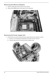
How Do I Replace The Power Supply In This Computer
my childred were using the computer and it just shut off with out any warning in the middle of what ...
my childred were using the computer and it just shut off with out any warning in the middle of what ...
(Posted by sbattl24 11 years ago)

Where Can I Buy A Power Supply For Acer Ax1800-u9002
The power supply unit on my Acer AX1800-U9002 died this evening and I need to purchase a new one. Pl...
The power supply unit on my Acer AX1800-U9002 died this evening and I need to purchase a new one. Pl...
(Posted by rcourtney671 11 years ago)