
Acer Aspire V5-531 Notebook Service Guide
Page 6
... Palmrest Module/Upper Case 3-18 Removing the Touchpad Board 3-21 Removing the Power Button Board 3-23 Removing the SATA Board 3-25 Removing the HDD Module 3-26 Removing the WLAN Module 3-27 Removing the Mainboard 3-29 Removing the Thermal Module 3-32 Removing the DC In Module 3-34 Removing the Battery Connector 3-35 Removing the Speaker Module 3-36 Removing the LCD Module 3-38 LCD...
... Palmrest Module/Upper Case 3-18 Removing the Touchpad Board 3-21 Removing the Power Button Board 3-23 Removing the SATA Board 3-25 Removing the HDD Module 3-26 Removing the WLAN Module 3-27 Removing the Mainboard 3-29 Removing the Thermal Module 3-32 Removing the DC In Module 3-34 Removing the Battery Connector 3-35 Removing the Speaker Module 3-36 Removing the LCD Module 3-38 LCD...
Acer Aspire V5-531 Notebook Service Guide
Page 23
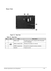
Releases the battery for removal. 3 DIMM compartment Houses the computer's memory modules. 4 Speaker Outputs sounds. Base View No. 1 2 Icon Item Battery pack Battery release latch Description Provides power to the computer when the power cord is unplugged. Base View Table 1-5. 0 Base View 0 Figure 1-5. Hardware Specifications and Configurations 1-15
Releases the battery for removal. 3 DIMM compartment Houses the computer's memory modules. 4 Speaker Outputs sounds. Base View No. 1 2 Icon Item Battery pack Battery release latch Description Provides power to the computer when the power cord is unplugged. Base View Table 1-5. 0 Base View 0 Figure 1-5. Hardware Specifications and Configurations 1-15
Acer Aspire V5-531 Notebook Service Guide
Page 75
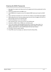
After the BIOS POST, remove the tool from the computer. 2. Press F9 to save the changes you made and close the Setup Utility. Press the button to turn on the ... the prompt appears, repeat steps 4-9 until the BIOS passwords have been cleared. If the DIMM2 slot is occupied, remove the installed DIMM module and locate the G2201 gap. 4. Reinstall the DIMM module, DIMM cover and battery pack. 9. Remove the battery pack and DIMM cover. 3. Turn on the hardware gap together. 5. Clearing the BIOS Passwords 0 1.
After the BIOS POST, remove the tool from the computer. 2. Press F9 to save the changes you made and close the Setup Utility. Press the button to turn on the ... the prompt appears, repeat steps 4-9 until the BIOS passwords have been cleared. If the DIMM2 slot is occupied, remove the installed DIMM module and locate the G2201 gap. 4. Reinstall the DIMM module, DIMM cover and battery pack. 9. Remove the battery pack and DIMM cover. 3. Turn on the hardware gap together. 5. Clearing the BIOS Passwords 0 1.
Acer Aspire V5-531 Notebook Service Guide
Page 78
... Palmrest Module/Upper Case 3-18 Removing the Touchpad Board 3-21 Removing the Power Button Board 3-23 Removing the SATA Board 3-25 Removing the HDD Module 3-26 Removing the WLAN Module 3-27 Removing the Mainboard 3-29 Removing the Thermal Module 3-32 Removing the DC In Module 3-34 Removing the Battery Connector 3-35 Removing the Speaker Module 3-36 Removing the LCD Module 3-38 LCD...
... Palmrest Module/Upper Case 3-18 Removing the Touchpad Board 3-21 Removing the Power Button Board 3-23 Removing the SATA Board 3-25 Removing the HDD Module 3-26 Removing the WLAN Module 3-27 Removing the Mainboard 3-29 Removing the Thermal Module 3-32 Removing the DC In Module 3-34 Removing the Battery Connector 3-35 Removing the Speaker Module 3-36 Removing the LCD Module 3-38 LCD...
Acer Aspire V5-531 Notebook Service Guide
Page 84
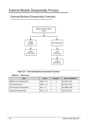
Screw List Step DIMM Cover Disassembly ODD Disassembly ODD Bracket Disassembly Keyboard Disassembly Screw M2.5 x L5 M2.5 × L5 M2 × L3 M2.5 × L5 Quantity 2 1 2 2 Acer Part Number 86.00J51.535 86.00J51.535 86.9A552.3R0 86.00J51.535 3-8 Machine Maintenance External Module Disassembly Process 0 External Modules Disassembly Flowchart 0 REMOVE BATTERY PACK DIMM COVER DIMM MODULES KEYBOARD ODD MODULE ODD BRACKET Figure 3-2. External Modules Disassembly Flowchart Table 3-2.
Screw List Step DIMM Cover Disassembly ODD Disassembly ODD Bracket Disassembly Keyboard Disassembly Screw M2.5 x L5 M2.5 × L5 M2 × L3 M2.5 × L5 Quantity 2 1 2 2 Acer Part Number 86.00J51.535 86.00J51.535 86.9A552.3R0 86.00J51.535 3-8 Machine Maintenance External Module Disassembly Process 0 External Modules Disassembly Flowchart 0 REMOVE BATTERY PACK DIMM COVER DIMM MODULES KEYBOARD ODD MODULE ODD BRACKET Figure 3-2. External Modules Disassembly Flowchart Table 3-2.
Acer Aspire V5-531 Notebook Service Guide
Page 85
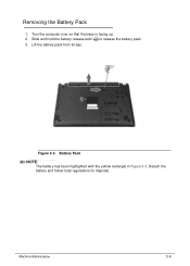
Turn the computer over so that the base is facing up. 2. Figure 3-3. Lift the battery pack from its bay. Machine Maintenance 3-9 Slide and hold the battery release latch to release the battery pack. 3. Battery Pack NOTE: NOTE: The battery has been highlighted with the yellow rectangle in Figure 3-3. Detach the battery and follow local regulations for disposal. Removing the Battery Pack 0 1.
Turn the computer over so that the base is facing up. 2. Figure 3-3. Lift the battery pack from its bay. Machine Maintenance 3-9 Slide and hold the battery release latch to release the battery pack. 3. Battery Pack NOTE: NOTE: The battery has been highlighted with the yellow rectangle in Figure 3-3. Detach the battery and follow local regulations for disposal. Removing the Battery Pack 0 1.
Acer Aspire V5-531 Notebook Service Guide
Page 86
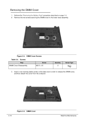
Remove the two screws securing the DIMM cover to release the DIMM cover, and then detach the cover from the computer. 3-10 Figure 3-5. Insert a non-marring plastic scribe on page 3-9. 2. DIMM Cover Screws Table 3-4. Figure 3-4. DIMM Cover Machine Maintenance Perform the "Removing the Battery Pack" procedure described on the base door's notch to the lower case assembly. Removing the DIMM Cover 0 1. Screws Step DIMM Cover Disassembly Screw M2.5 × L5 Quantity 2 Screw Type 3.
Remove the two screws securing the DIMM cover to release the DIMM cover, and then detach the cover from the computer. 3-10 Figure 3-5. Insert a non-marring plastic scribe on page 3-9. 2. DIMM Cover Screws Table 3-4. Figure 3-4. DIMM Cover Machine Maintenance Perform the "Removing the Battery Pack" procedure described on the base door's notch to the lower case assembly. Removing the DIMM Cover 0 1. Screws Step DIMM Cover Disassembly Screw M2.5 × L5 Quantity 2 Screw Type 3.
Acer Aspire V5-531 Notebook Service Guide
Page 88
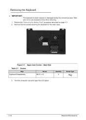
Upper Case Screws - Removing the Keyboard 0 + IMPORTANT: The keyboard is easily warped or damaged during the removal process. Figure 3-7. Turn the computer over and open the LCD panel. 3-12 Machine Maintenance Base Side Table 3-7. Remove the two screws securing the keyboard to use excessive force when removing. 1. Screws Step Keyboard Disassembly Screw M2.5 × L5 Quantity 2 Screw Type 3. Perform the "Removing the Battery Pack" procedure described on page 3-9. 2. Take care not to the lower case.
Upper Case Screws - Removing the Keyboard 0 + IMPORTANT: The keyboard is easily warped or damaged during the removal process. Figure 3-7. Turn the computer over and open the LCD panel. 3-12 Machine Maintenance Base Side Table 3-7. Remove the two screws securing the keyboard to use excessive force when removing. 1. Screws Step Keyboard Disassembly Screw M2.5 × L5 Quantity 2 Screw Type 3. Perform the "Removing the Battery Pack" procedure described on page 3-9. 2. Take care not to the lower case.
Acer Aspire V5-531 Notebook Service Guide
Page 111
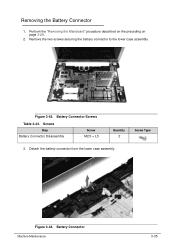
Figure 3-44. Perform the "Removing the Mainboard" procedure described on the preceding on page 3-29. 2. Battery Connector Machine Maintenance 3-35 Battery Connector Screws Table 3-43. Screws Step Battery Connector Disassembly Screw M2.5 × L5 Quantity 2 Screw Type 3. Figure 3-43. Detach the battery connector from the lower case assembly. Remove the two screws securing the battery connector to the lower case assembly. Removing the Battery Connector 0 1.
Figure 3-44. Perform the "Removing the Mainboard" procedure described on the preceding on page 3-29. 2. Battery Connector Machine Maintenance 3-35 Battery Connector Screws Table 3-43. Screws Step Battery Connector Disassembly Screw M2.5 × L5 Quantity 2 Screw Type 3. Figure 3-43. Detach the battery connector from the lower case assembly. Remove the two screws securing the battery connector to the lower case assembly. Removing the Battery Connector 0 1.
Acer Aspire V5-531 Notebook Service Guide
Page 164
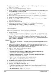
...Manager to the previous version if updated. 5. Perform the "Removing the LCD Module" and "Removing the Camera Board" procedures described on pages 3-66 and 3-74 respectively. 12. Adjust the brightness to the Online Support Information on battery alone as this may reduce display brightness. 2. If the... computer boots correctly, add the devices one by removing the power cable and the battery pack. If the issue is faulty and should be replaced. ...
...Manager to the previous version if updated. 5. Perform the "Removing the LCD Module" and "Removing the Camera Board" procedures described on pages 3-66 and 3-74 respectively. 12. Adjust the brightness to the Online Support Information on battery alone as this may reduce display brightness. 2. If the... computer boots correctly, add the devices one by removing the power cable and the battery pack. If the issue is faulty and should be replaced. ...
Acer Aspire V5-531 Notebook Service Guide
Page 176
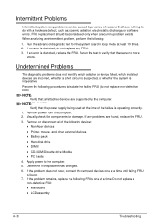
... defect, such as: cosmic radiation, electrostatic discharge, or software errors. If any FRU. 3. If the problem does not recur, connect the removed devices one at a time until failing FRU is found , replace the FRU. 3. Perform the following FRUs one at a time. Apply power... by the computer. When analyzing an intermittent problem, perform the following devices: Non-Acer devices Printer, mouse, and other external devices Battery pack Hard disk drive DIMM CD-ROM/Diskette drive Module...
... defect, such as: cosmic radiation, electrostatic discharge, or software errors. If any FRU. 3. If the problem does not recur, connect the removed devices one at a time until failing FRU is found , replace the FRU. 3. Perform the following FRUs one at a time. Apply power... by the computer. When analyzing an intermittent problem, perform the following devices: Non-Acer devices Printer, mouse, and other external devices Battery pack Hard disk drive DIMM CD-ROM/Diskette drive Module...
Acer Aspire V5-531 Notebook Service Guide
Page 195
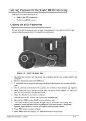
... Passwords 0 To clear a lost BIOS password (user or supervisor password), you made and close the Setup Utility. Remove the battery pack and DIMM cover. 3. Reinstall the DIMM module, DIMM cover and battery pack. 9. Press F10 to save the changes you need to load the system defaults. 11. If the DIMM2... slot is occupied, remove the installed DIMM module and locate the G2201 gap. 4. Figure 2-5. Shut down the computer and ...
... Passwords 0 To clear a lost BIOS password (user or supervisor password), you made and close the Setup Utility. Remove the battery pack and DIMM cover. 3. Reinstall the DIMM module, DIMM cover and battery pack. 9. Press F10 to save the changes you need to load the system defaults. 11. If the DIMM2... slot is occupied, remove the installed DIMM module and locate the G2201 gap. 4. Figure 2-5. Shut down the computer and ...


