
Acer Aspire V5-531 Notebook Service Guide
Page 3
... that represents information entered by a computer user, such as menus, prompts, responses to know for personal injury. ! Example: At the prompt, type run -m Keyboard keys are shown in italics. Example: [01] The server has been stopped User input (text that is important to input, and error messages...
... that represents information entered by a computer user, such as menus, prompts, responses to know for personal injury. ! Example: At the prompt, type run -m Keyboard keys are shown in italics. Example: [01] The server has been stopped User input (text that is important to input, and error messages...
Acer Aspire V5-531 Notebook Service Guide
Page 5
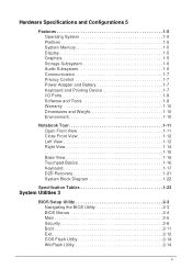
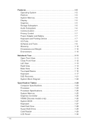
... Platform 1-5 System Memory 1-5 Display 1-5 Graphics 1-5 Storage Subsystem 1-6 Audio Subsystem 1-6 Communication 1-7 Privacy Control 1-7 Power Adapter and Battery 1-7 Keyboard and Pointing Device 1-7 I/O Ports 1-8 Software and Tools 1-8 Warranty 1-10 Dimensions and Weight 1-10 Environment 1-10 Notebook Tour 1-11 Open... View 1-11 Close Front View 1-12 Left View 1-13 Right View 1-14 1-15 Base View 1-15 Touchpad Basics 1-16 Keyboard 1-17 D2D Recovery 1-21 System Block Diagram 1-22 Specification Tables 1-23 System Utilities 3 BIOS Setup Utility 2-3 Navigating the BIOS...
... Platform 1-5 System Memory 1-5 Display 1-5 Graphics 1-5 Storage Subsystem 1-6 Audio Subsystem 1-6 Communication 1-7 Privacy Control 1-7 Power Adapter and Battery 1-7 Keyboard and Pointing Device 1-7 I/O Ports 1-8 Software and Tools 1-8 Warranty 1-10 Dimensions and Weight 1-10 Environment 1-10 Notebook Tour 1-11 Open... View 1-11 Close Front View 1-12 Left View 1-13 Right View 1-14 1-15 Base View 1-15 Touchpad Basics 1-16 Keyboard 1-17 D2D Recovery 1-21 System Block Diagram 1-22 Specification Tables 1-23 System Utilities 3 BIOS Setup Utility 2-3 Navigating the BIOS...
Acer Aspire V5-531 Notebook Service Guide
Page 6
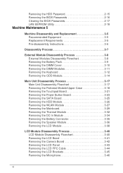
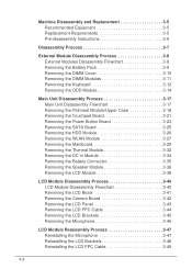
... Process 3-7 External Module Disassembly Process 3-8 External Modules Disassembly Flowchart 3-8 Removing the Battery Pack 3-9 Removing the DIMM Cover 3-10 Removing the DIMM Modules 3-11 Removing the Keyboard 3-12 Removing the ODD Module 3-14 Main Unit Disassembly Process 3-17 Main Unit Disassembly Flowchart 3-17 Removing the Palmrest Module/Upper Case 3-18 Removing the...
... Process 3-7 External Module Disassembly Process 3-8 External Modules Disassembly Flowchart 3-8 Removing the Battery Pack 3-9 Removing the DIMM Cover 3-10 Removing the DIMM Modules 3-11 Removing the Keyboard 3-12 Removing the ODD Module 3-14 Main Unit Disassembly Process 3-17 Main Unit Disassembly Flowchart 3-17 Removing the Palmrest Module/Upper Case 3-18 Removing the...
Acer Aspire V5-531 Notebook Service Guide
Page 7
... Reinstalling the Palmrest Module/Upper Case 3-72 External Module Reassembly Process 3-74 Reinstalling the ODD Module 3-74 Reinstalling the Keyboard 3-77 Reinstalling the DIMM Modules 3-79 Reinstalling the DIMM Cover 3-80 Reinstalling the Battery Pack 3-81 Troubleshooting 3 Introduction... 4-3 General Information 4-3 Power On Issues 4-4 No Display Issues 4-5 LCD Failure 4-7 Keyboard Failure 4-8 Touchpad Failure 4-9 Internal Speaker Failure 4-10 Microphone Failure 4-12 USB Failure 4-13 WLAN Failure 4-14 Card Reader Failure...
... Reinstalling the Palmrest Module/Upper Case 3-72 External Module Reassembly Process 3-74 Reinstalling the ODD Module 3-74 Reinstalling the Keyboard 3-77 Reinstalling the DIMM Modules 3-79 Reinstalling the DIMM Cover 3-80 Reinstalling the Battery Pack 3-81 Troubleshooting 3 Introduction... 4-3 General Information 4-3 Power On Issues 4-4 No Display Issues 4-5 LCD Failure 4-7 Keyboard Failure 4-8 Touchpad Failure 4-9 Internal Speaker Failure 4-10 Microphone Failure 4-12 USB Failure 4-13 WLAN Failure 4-14 Card Reader Failure...
Acer Aspire V5-531 Notebook Service Guide
Page 10
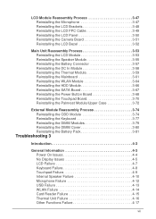
... 1-5 System Memory 1-5 Display 1-5 Graphics 1-5 Storage Subsystem 1-6 Audio Subsystem 1-6 Communication 1-7 Privacy Control 1-7 Power Adapter and Battery 1-7 Keyboard and Pointing Device 1-7 I/O Ports 1-8 Software and Tools 1-8 Warranty 1-10 Dimensions and Weight 1-10 Environment 1-10 Notebook Tour 1-11...Open Front View 1-11 Close Front View 1-12 Left View 1-13 Right View 1-14 Base View 1-15 Touchpad Basics 1-16 Keyboard 1-17 D2D Recovery 1-21 System Block Diagram 1-22 Specification Tables 1-23 Computer Specifications 1-23 Processor 1-24 Processor Specifications 1-25...
... 1-5 System Memory 1-5 Display 1-5 Graphics 1-5 Storage Subsystem 1-6 Audio Subsystem 1-6 Communication 1-7 Privacy Control 1-7 Power Adapter and Battery 1-7 Keyboard and Pointing Device 1-7 I/O Ports 1-8 Software and Tools 1-8 Warranty 1-10 Dimensions and Weight 1-10 Environment 1-10 Notebook Tour 1-11...Open Front View 1-11 Close Front View 1-12 Left View 1-13 Right View 1-14 Base View 1-15 Touchpad Basics 1-16 Keyboard 1-17 D2D Recovery 1-21 System Block Diagram 1-22 Specification Tables 1-23 Computer Specifications 1-23 Processor 1-24 Processor Specifications 1-25...
Acer Aspire V5-531 Notebook Service Guide
Page 15
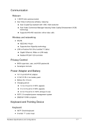
...215;480 resolution online video calls Wireless and networking 0 WLAN: IEEE 802.11b/g/n Supports Acer SignalUp technology LAN on Feature Port (thru bundled Y Cable): Gigabit Ethernet, Wake-on-LAN ready ...hours for 0-100% (charge-in-use) ACPI 3.0-compliant power management system ENERGY STAR compliant Keyboard and Pointing Device 0 Keyboard 0 AS7F Chiclet keyboard Inverted "T" cursor keys Hardware Specifications and Configurations 1-7
...215;480 resolution online video calls Wireless and networking 0 WLAN: IEEE 802.11b/g/n Supports Acer SignalUp technology LAN on Feature Port (thru bundled Y Cable): Gigabit Ethernet, Wake-on-LAN ready ...hours for 0-100% (charge-in-use) ACPI 3.0-compliant power management system ENERGY STAR compliant Keyboard and Pointing Device 0 Keyboard 0 AS7F Chiclet keyboard Inverted "T" cursor keys Hardware Specifications and Configurations 1-7
Acer Aspire V5-531 Notebook Service Guide
Page 19
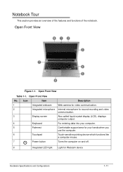
... crystal display (LCD), displays computer output. Power button Turns the computer on and off. 8 Integrated LED light Light for your computer. Open Front View 0 Figure 1-1. Keyboard For entering data into your hands when you use the computer. Touchpad Touch-sensitive pointing device which functions like a computer mouse. Palmrest Comfortable support area...
... crystal display (LCD), displays computer output. Power button Turns the computer on and off. 8 Integrated LED light Light for your computer. Open Front View 0 Figure 1-1. Keyboard For entering data into your hands when you use the computer. Touchpad Touch-sensitive pointing device which functions like a computer mouse. Palmrest Comfortable support area...
Acer Aspire V5-531 Notebook Service Guide
Page 25
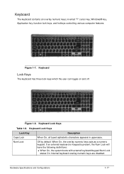
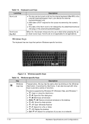
... can toggle on and off. Keyboard Lock Keys Table 1-8. Internal keyboard overlay numeric keys are disabled. Keyboard Lock Keys Lock Key Caps Lock Num Lock Description When On, all typed alphabetic characters appears in uppercase. Figure 1-8. Keyboard 0 The keyboard contains an overlay numeric keys, ... keys, and hotkeys controlling various computer features. If an external keyboard or keypad is present, the Num Lock will have the following definitions: When On, the system boots with external keyboard/keypad Num Lock status On. Hardware Specifications and Configurations 1-17 ...
... can toggle on and off. Keyboard Lock Keys Table 1-8. Internal keyboard overlay numeric keys are disabled. Keyboard Lock Keys Lock Key Caps Lock Num Lock Description When On, all typed alphabetic characters appears in uppercase. Figure 1-8. Keyboard 0 The keyboard contains an overlay numeric keys, ... keys, and hotkeys controlling various computer features. If an external keyboard or keypad is present, the Num Lock will have the following definitions: When On, the system boots with external keyboard/keypad Num Lock status On. Hardware Specifications and Configurations 1-17 ...
Acer Aspire V5-531 Notebook Service Guide
Page 26
... numeric keys. The state of the Num Lock is not applicable for computers (if you are on /off via the internal keyboard (Fn+F11) or the external keyboard/keypad. It can be used with other keys to the desktop +F1: Show the Help window + E: Open ...line up or down when pressing the up or down cursor keys. Figure 1-9. Functions supported by the attachment/removal (hot plug) of functions. Keyboard Lock Keys Lock Key Description Num Lock The key can also be turned on a network) 1-18 Hardware Specifications and Configurations Windows Keys 0...
... numeric keys. The state of the Num Lock is not applicable for computers (if you are on /off via the internal keyboard (Fn+F11) or the external keyboard/keypad. It can be used with other keys to the desktop +F1: Show the Help window + E: Open ...line up or down when pressing the up or down cursor keys. Figure 1-9. Functions supported by the attachment/removal (hot plug) of functions. Keyboard Lock Keys Lock Key Description Num Lock The key can also be turned on a network) 1-18 Hardware Specifications and Configurations Windows Keys 0...
Acer Aspire V5-531 Notebook Service Guide
Page 35
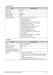
... bus specification v2.0 AHCI support Microsoft XP/Vista/Windows 7 logo program Microsoft SLP 1.0 support Microsoft OA 2.0 and 2.1 support Keyboard Item Specification Type AS7F Chiclet keyboard Total number of keys 88/89/93 keys Windows logo key Yes Internal and external USB Yes... keyboard work simultaneously? Features Inverted "T" cursor keys Hotkeys for volume and brightness level, media playback, wireless and sleep functions, and ...
... bus specification v2.0 AHCI support Microsoft XP/Vista/Windows 7 logo program Microsoft SLP 1.0 support Microsoft OA 2.0 and 2.1 support Keyboard Item Specification Type AS7F Chiclet keyboard Total number of keys 88/89/93 keys Windows logo key Yes Internal and external USB Yes... keyboard work simultaneously? Features Inverted "T" cursor keys Hotkeys for volume and brightness level, media playback, wireless and sleep functions, and ...
Acer Aspire V5-531 Notebook Service Guide
Page 49
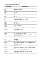
... 16 IRQ 0 IRQ 4294967291 IRQ 18 IRQ 1 IRQ 4294967294 IRQ 19 IRQ 19 IRQ 19 IRQ 8 System Function System timer Standard PS/2 keyboard Not in use Not in use Not in use Not in use Not in use System CMOS/real time clock Broadcom xD Picture Card Host...Chipset Family USB Enhanced Host Controller - 1E2D System timer Realtek PCIE CardReader Intel(R) 7 Series/C216 Chipset Family PCI Express Root Port 3 1E14 Standard PS/2 Keyboard Realtek PCIe GBE Family Controller Intel(R) 7 Series/C216 Chipset Family PCI Express Root Port 4 1E16 Qualcomm Atheros AR5BWB222 Wireless Network Adapter Intel(R) 7 Series ...
... 16 IRQ 0 IRQ 4294967291 IRQ 18 IRQ 1 IRQ 4294967294 IRQ 19 IRQ 19 IRQ 19 IRQ 8 System Function System timer Standard PS/2 keyboard Not in use Not in use Not in use Not in use Not in use System CMOS/real time clock Broadcom xD Picture Card Host...Chipset Family USB Enhanced Host Controller - 1E2D System timer Realtek PCIE CardReader Intel(R) 7 Series/C216 Chipset Family PCI Express Root Port 3 1E14 Standard PS/2 Keyboard Realtek PCIe GBE Family Controller Intel(R) 7 Series/C216 Chipset Family PCI Express Root Port 4 1E16 Qualcomm Atheros AR5BWB222 Wireless Network Adapter Intel(R) 7 Series ...
Acer Aspire V5-531 Notebook Service Guide
Page 55
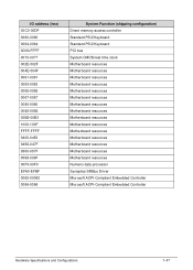
... 0458-047F 0500-057F 0068-006F 00F0-00F0 EFA0-EFBF 0062-00062 0066-0066 System Function (shipping configuration) Direct memory access controller Standard PS/2 Keyboard Standard PS/2 Keyboard PCI bus System CMOS/real time clock Motherboard resources Motherboard resources Motherboard resources Motherboard resources Motherboard resources Motherboard resources Motherboard resources Motherboard resources Motherboard...
... 0458-047F 0500-057F 0068-006F 00F0-00F0 EFA0-EFBF 0062-00062 0066-0066 System Function (shipping configuration) Direct memory access controller Standard PS/2 Keyboard Standard PS/2 Keyboard PCI bus System CMOS/real time clock Motherboard resources Motherboard resources Motherboard resources Motherboard resources Motherboard resources Motherboard resources Motherboard resources Motherboard resources Motherboard...
Acer Aspire V5-531 Notebook Service Guide
Page 62
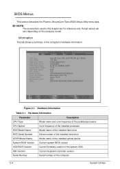
... number of the installed hard drive Model name of the installed optical device Current system BIOS version Current firmware version of the system VGA Current keyboard controller version Serial number of the computer's hardware information. Information 0 This tab shows a summary of the computer 2-4 System Utilities
... number of the installed hard drive Model name of the installed optical device Current system BIOS version Current firmware version of the system VGA Current keyboard controller version Serial number of the computer's hardware information. Information 0 This tab shows a summary of the computer 2-4 System Utilities
Acer Aspire V5-531 Notebook Service Guide
Page 78
... Process 3-7 External Module Disassembly Process 3-8 External Modules Disassembly Flowchart 3-8 Removing the Battery Pack 3-9 Removing the DIMM Cover 3-10 Removing the DIMM Modules 3-11 Removing the Keyboard 3-12 Removing the ODD Module 3-14 Main Unit Disassembly Process 3-17 Main Unit Disassembly Flowchart 3-17 Removing the Palmrest Module/Upper Case 3-18 Removing the...
... Process 3-7 External Module Disassembly Process 3-8 External Modules Disassembly Flowchart 3-8 Removing the Battery Pack 3-9 Removing the DIMM Cover 3-10 Removing the DIMM Modules 3-11 Removing the Keyboard 3-12 Removing the ODD Module 3-14 Main Unit Disassembly Process 3-17 Main Unit Disassembly Flowchart 3-17 Removing the Palmrest Module/Upper Case 3-18 Removing the...
Acer Aspire V5-531 Notebook Service Guide
Page 79
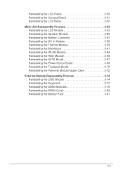
... 3-68 Reinstalling the Touchpad Board 3-70 Reinstalling the Palmrest Module/Upper Case 3-72 External Module Reassembly Process 3-74 Reinstalling the ODD Module 3-74 Reinstalling the Keyboard 3-77 Reinstalling the DIMM Modules 3-79 Reinstalling the DIMM Cover 3-80 Reinstalling the Battery Pack 3-81 3-3
... 3-68 Reinstalling the Touchpad Board 3-70 Reinstalling the Palmrest Module/Upper Case 3-72 External Module Reassembly Process 3-74 Reinstalling the ODD Module 3-74 Reinstalling the Keyboard 3-77 Reinstalling the DIMM Modules 3-79 Reinstalling the DIMM Cover 3-80 Reinstalling the Battery Pack 3-81 3-3
Acer Aspire V5-531 Notebook Service Guide
Page 83
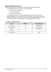
...;Main Unit Disassembly LCD Module Disassembly The flowcharts provided in that order. For example, if you must first remove the keyboard, then disassemble the inside assembly frame in the succeeding disassembly sections illustrate the entire disassembly sequence. Table 3-1. Main Screw List Screw M2 x... L3 M2 x L3 (black) M2.5 x L5 M2 x 3 Thermal Screw Quantity 10 10 27 1 5 Acer Part Number 86.9A552.3R0 86.00J40.323 86.00J51.535 N/A Machine Maintenance 3-7 Observe the order of the sequence to avoid damage to remove the...
...;Main Unit Disassembly LCD Module Disassembly The flowcharts provided in that order. For example, if you must first remove the keyboard, then disassemble the inside assembly frame in the succeeding disassembly sections illustrate the entire disassembly sequence. Table 3-1. Main Screw List Screw M2 x... L3 M2 x L3 (black) M2.5 x L5 M2 x 3 Thermal Screw Quantity 10 10 27 1 5 Acer Part Number 86.9A552.3R0 86.00J40.323 86.00J51.535 N/A Machine Maintenance 3-7 Observe the order of the sequence to avoid damage to remove the...
Acer Aspire V5-531 Notebook Service Guide
Page 84
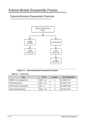
External Modules Disassembly Flowchart Table 3-2. Screw List Step DIMM Cover Disassembly ODD Disassembly ODD Bracket Disassembly Keyboard Disassembly Screw M2.5 x L5 M2.5 × L5 M2 × L3 M2.5 × L5 Quantity 2 1 2 2 Acer Part Number 86.00J51.535 86.00J51.535 86.9A552.3R0 86.00J51.535 3-8 Machine Maintenance External Module Disassembly Process 0 External Modules Disassembly Flowchart 0 REMOVE BATTERY PACK DIMM COVER DIMM MODULES KEYBOARD ODD MODULE ODD BRACKET Figure 3-2.
External Modules Disassembly Flowchart Table 3-2. Screw List Step DIMM Cover Disassembly ODD Disassembly ODD Bracket Disassembly Keyboard Disassembly Screw M2.5 x L5 M2.5 × L5 M2 × L3 M2.5 × L5 Quantity 2 1 2 2 Acer Part Number 86.00J51.535 86.00J51.535 86.9A552.3R0 86.00J51.535 3-8 Machine Maintenance External Module Disassembly Process 0 External Modules Disassembly Flowchart 0 REMOVE BATTERY PACK DIMM COVER DIMM MODULES KEYBOARD ODD MODULE ODD BRACKET Figure 3-2.
Acer Aspire V5-531 Notebook Service Guide
Page 88
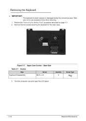
Removing the Keyboard 0 + IMPORTANT: The keyboard is easily warped or damaged during the removal process. Take care not to the lower case. Upper Case Screws - Turn the computer over and open the LCD panel. 3-12 Machine Maintenance Remove the two screws securing the keyboard to use excessive force when removing. 1. Figure 3-7. Base Side Table 3-7. Screws Step Keyboard Disassembly Screw M2.5 × L5 Quantity 2 Screw Type 3. Perform the "Removing the Battery Pack" procedure described on page 3-9. 2.
Removing the Keyboard 0 + IMPORTANT: The keyboard is easily warped or damaged during the removal process. Take care not to the lower case. Upper Case Screws - Turn the computer over and open the LCD panel. 3-12 Machine Maintenance Remove the two screws securing the keyboard to use excessive force when removing. 1. Figure 3-7. Base Side Table 3-7. Screws Step Keyboard Disassembly Screw M2.5 × L5 Quantity 2 Screw Type 3. Perform the "Removing the Battery Pack" procedure described on page 3-9. 2.
Acer Aspire V5-531 Notebook Service Guide
Page 89
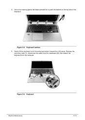
Figure 3-9. Use a non-marring plastic flat-blade screwdriver to push the latches on the top side of its socket and slide it toward the LCD panel. Release the connector latch (1), disconnect the cable from the mainboard (2), then detach the keyboard from the computer. 4. Gently lift the keyboard out of the keyboard. Figure 3-8. Keyboard Machine Maintenance 3-13 Keyboard Latches 5.
Figure 3-9. Use a non-marring plastic flat-blade screwdriver to push the latches on the top side of its socket and slide it toward the LCD panel. Release the connector latch (1), disconnect the cable from the mainboard (2), then detach the keyboard from the computer. 4. Gently lift the keyboard out of the keyboard. Figure 3-8. Keyboard Machine Maintenance 3-13 Keyboard Latches 5.
Acer Aspire V5-531 Notebook Service Guide
Page 90
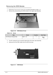
Perform the "Removing the Keyboard" procedure described on page 3-12. 2. ODD Module 3-14 Machine Maintenance Screw Step ODD Module Disassembly Screw M2.5 × L5 Quantity 1 Screw Type 3. Figure 3-11. Figure 3-10. Gently pull out the ODD module from the ODD drive bay. Turn the computer over to the upper case assembly. Remove the screw securing the ODD module to acces the base side of the lower case assembly. 4. Removing the ODD Module 0 1. ODD Module Screw Table 3-10.
Perform the "Removing the Keyboard" procedure described on page 3-12. 2. ODD Module 3-14 Machine Maintenance Screw Step ODD Module Disassembly Screw M2.5 × L5 Quantity 1 Screw Type 3. Figure 3-11. Figure 3-10. Gently pull out the ODD module from the ODD drive bay. Turn the computer over to the upper case assembly. Remove the screw securing the ODD module to acces the base side of the lower case assembly. 4. Removing the ODD Module 0 1. ODD Module Screw Table 3-10.


