
Acer Aspire V5-531 Notebook Service Guide
Page 5
Hardware Specifications and Configurations 5 Features 1-5 Operating System 1-5 Platform 1-5 System Memory 1-5 Display 1-5 Graphics 1-5 Storage Subsystem 1-6 Audio Subsystem 1-6 Communication 1-7 Privacy Control 1-7 Power Adapter and Battery 1-7 Keyboard and Pointing Device 1-7 I/O Ports 1-8 Software and Tools 1-8 Warranty 1-10 Dimensions and Weight 1-10 Environment 1-10 Notebook Tour 1-11 Open Front View 1-11 Close Front ...
Hardware Specifications and Configurations 5 Features 1-5 Operating System 1-5 Platform 1-5 System Memory 1-5 Display 1-5 Graphics 1-5 Storage Subsystem 1-6 Audio Subsystem 1-6 Communication 1-7 Privacy Control 1-7 Power Adapter and Battery 1-7 Keyboard and Pointing Device 1-7 I/O Ports 1-8 Software and Tools 1-8 Warranty 1-10 Dimensions and Weight 1-10 Environment 1-10 Notebook Tour 1-11 Open Front View 1-11 Close Front ...
Acer Aspire V5-531 Notebook Service Guide
Page 6
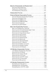
...Equipment 3-5 Replacement Requirements 3-5 Pre-disassembly Instructions 3-6 Disassembly Process 3-7 External Module Disassembly Process 3-8 External Modules Disassembly Flowchart 3-8 Removing the Battery Pack 3-9 Removing the DIMM Cover 3-10 Removing the DIMM Modules 3-11 Removing the Keyboard 3-12 Removing the ODD Module 3-14 Main ...Module 3-27 Removing the Mainboard 3-29 Removing the Thermal Module 3-32 Removing the DC In Module 3-34 Removing the Battery Connector 3-35 Removing the Speaker Module 3-36 Removing the LCD Module 3-38 LCD Module Disassembly Process 3-40 LCD ...
...Equipment 3-5 Replacement Requirements 3-5 Pre-disassembly Instructions 3-6 Disassembly Process 3-7 External Module Disassembly Process 3-8 External Modules Disassembly Flowchart 3-8 Removing the Battery Pack 3-9 Removing the DIMM Cover 3-10 Removing the DIMM Modules 3-11 Removing the Keyboard 3-12 Removing the ODD Module 3-14 Main ...Module 3-27 Removing the Mainboard 3-29 Removing the Thermal Module 3-32 Removing the DC In Module 3-34 Removing the Battery Connector 3-35 Removing the Speaker Module 3-36 Removing the LCD Module 3-38 LCD Module Disassembly Process 3-40 LCD ...
Acer Aspire V5-531 Notebook Service Guide
Page 7
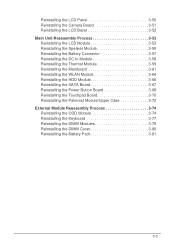
... 3-52 Main Unit Reassembly Process 3-53 Reinstalling the LCD Module 3-53 Reinstalling the Speaker Module 3-55 Reinstalling the Battery Connector 3-57 Reinstalling the DC In Module 3-58 Reinstalling the Thermal Module 3-59 Reinstalling the Mainboard 3-61 Reinstalling ...74 Reinstalling the ODD Module 3-74 Reinstalling the Keyboard 3-77 Reinstalling the DIMM Modules 3-79 Reinstalling the DIMM Cover 3-80 Reinstalling the Battery Pack 3-81 Troubleshooting 3 Introduction 4-3 General Information 4-3 Power On Issues 4-4 No Display Issues 4-5 LCD Failure 4-7 Keyboard Failure 4-8 ...
... 3-52 Main Unit Reassembly Process 3-53 Reinstalling the LCD Module 3-53 Reinstalling the Speaker Module 3-55 Reinstalling the Battery Connector 3-57 Reinstalling the DC In Module 3-58 Reinstalling the Thermal Module 3-59 Reinstalling the Mainboard 3-61 Reinstalling ...74 Reinstalling the ODD Module 3-74 Reinstalling the Keyboard 3-77 Reinstalling the DIMM Modules 3-79 Reinstalling the DIMM Cover 3-80 Reinstalling the Battery Pack 3-81 Troubleshooting 3 Introduction 4-3 General Information 4-3 Power On Issues 4-4 No Display Issues 4-5 LCD Failure 4-7 Keyboard Failure 4-8 ...
Acer Aspire V5-531 Notebook Service Guide
Page 10
Features 1-5 Operating System 1-5 Platform 1-5 System Memory 1-5 Display 1-5 Graphics 1-5 Storage Subsystem 1-6 Audio Subsystem 1-6 Communication 1-7 Privacy Control 1-7 Power Adapter and Battery 1-7 Keyboard and Pointing Device 1-7 I/O Ports 1-8 Software and Tools 1-8 Warranty 1-10 Dimensions and Weight 1-10 Environment 1-10 Notebook Tour 1-11 Open Front View 1-11 Close Front ...
Features 1-5 Operating System 1-5 Platform 1-5 System Memory 1-5 Display 1-5 Graphics 1-5 Storage Subsystem 1-6 Audio Subsystem 1-6 Communication 1-7 Privacy Control 1-7 Power Adapter and Battery 1-7 Keyboard and Pointing Device 1-7 I/O Ports 1-8 Software and Tools 1-8 Warranty 1-10 Dimensions and Weight 1-10 Environment 1-10 Notebook Tour 1-11 Open Front View 1-11 Close Front ...
Acer Aspire V5-531 Notebook Service Guide
Page 15
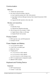
...215;480 resolution online video calls Wireless and networking 0 WLAN: IEEE 802.11b/g/n Supports Acer SignalUp technology LAN on Feature Port (thru bundled Y Cable): Gigabit Ethernet, Wake-on-LAN ready ...;BIOS supervisor, user, and HDD passwords Kensington lock slot Power Adapter and Battery 0 19 V 3-pin 65 W AC adapter 4-Cell 2.8 Ah Li-ion battery pack Battery life: 4 hours Charging period: 1.5 to 2 hours for ...
...215;480 resolution online video calls Wireless and networking 0 WLAN: IEEE 802.11b/g/n Supports Acer SignalUp technology LAN on Feature Port (thru bundled Y Cable): Gigabit Ethernet, Wake-on-LAN ready ...;BIOS supervisor, user, and HDD passwords Kensington lock slot Power Adapter and Battery 0 19 V 3-pin 65 W AC adapter 4-Cell 2.8 Ah Li-ion battery pack Battery life: 4 hours Charging period: 1.5 to 2 hours for ...
Acer Aspire V5-531 Notebook Service Guide
Page 18
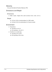
...; Height: 381.6 x 253 x 20.6mm (15.02 × 9.96 × 0.81 in) Weight 0 2.23 kg (4.92 lb) (including battery) for UMA models 2.28 kg (5.03 lb) (including battery) for Discrete models Environment 0 Temperature: Operating: 0 to 40 °C Non-operating: -20 to 60...
...; Height: 381.6 x 253 x 20.6mm (15.02 × 9.96 × 0.81 in) Weight 0 2.23 kg (4.92 lb) (including battery) for UMA models 2.28 kg (5.03 lb) (including battery) for Discrete models Environment 0 Temperature: Operating: 0 to 40 °C Non-operating: -20 to 60...
Acer Aspire V5-531 Notebook Service Guide
Page 20
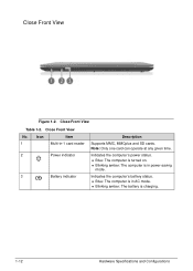
... Configurations Icon Item 1 Multi-in power-saving mode. Close Front View Table 1-2. Indicates the computer's battery status. Blue: The computer is in AC mode. Blinking amber: The battery is in -1 card reader 2 Power indicator 3 Battery indicator Description Supports MMC, MMCplus and SD cards. Close Front View No. Close Front View 0 Figure...
... Configurations Icon Item 1 Multi-in power-saving mode. Close Front View Table 1-2. Indicates the computer's battery status. Blue: The computer is in AC mode. Blinking amber: The battery is in -1 card reader 2 Power indicator 3 Battery indicator Description Supports MMC, MMCplus and SD cards. Close Front View No. Close Front View 0 Figure...
Acer Aspire V5-531 Notebook Service Guide
Page 23
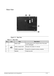
Base View No. 1 2 Icon Item Battery pack Battery release latch Description Provides power to the computer when the power cord is unplugged. Releases the battery for removal. 3 DIMM compartment Houses the computer's memory modules. 4 Speaker Outputs sounds. Hardware Specifications and Configurations 1-15 0 Base View 0 Figure 1-5. Base View Table 1-5.
Base View No. 1 2 Icon Item Battery pack Battery release latch Description Provides power to the computer when the power cord is unplugged. Releases the battery for removal. 3 DIMM compartment Houses the computer's memory modules. 4 Speaker Outputs sounds. Hardware Specifications and Configurations 1-15 0 Base View 0 Figure 1-5. Base View Table 1-5.
Acer Aspire V5-531 Notebook Service Guide
Page 31
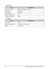
... Dimensions Width 38.2 cm 15.02 in Depth 25.3 cm 9.96 in Height 2.06 cm 0.81 in Weight (equipped with 4-cell 2.23 kg for UMA battery pack, HDD, and ODD) 2.28 kg for Discrete 4.92 lb for UMA 5.03 lb for Discrete Input power Operating voltage 19 V, 65 W Operating current (max...
... Dimensions Width 38.2 cm 15.02 in Depth 25.3 cm 9.96 in Height 2.06 cm 0.81 in Weight (equipped with 4-cell 2.23 kg for UMA battery pack, HDD, and ODD) 2.28 kg for Discrete 4.92 lb for UMA 5.03 lb for Discrete Input power Operating voltage 19 V, 65 W Operating current (max...
Acer Aspire V5-531 Notebook Service Guide
Page 41
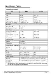
...Express Chipset USB 2.0 - Flashes blue when there is an active wireless connection. AC adapter disconnected: Blinking amber: Battery charge is turned off : Discharging state. Flashes amber when there is hard drive activity. Integrated in critically low state Indicator off...and location of slot Supported card Specification PCI Express Mini Card 1 WLAN or WiMAX module System LED Indicators Item Power status Battery status HDD activity Wireless connectivity Specification Solid blue: The computer is turned on. Blinking amber: The ...
...Express Chipset USB 2.0 - Flashes blue when there is an active wireless connection. AC adapter disconnected: Blinking amber: Battery charge is turned off : Discharging state. Flashes amber when there is hard drive activity. Integrated in critically low state Indicator off...and location of slot Supported card Specification PCI Express Mini Card 1 WLAN or WiMAX module System LED Indicators Item Power status Battery status HDD activity Wireless connectivity Specification Solid blue: The computer is turned on. Blinking amber: The ...
Acer Aspire V5-531 Notebook Service Guide
Page 42
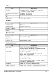
Battery Pack Item Vendor and models Battery type Pack capacity Number of battery cell Package configuration AC Adapter Item Input rating Input AC current (max) Output Specification SANYO AL12A32 Li-Ion 4S1P Lithium-ion 2600 mAh 4 3S2P Specification 65 W 100-240 V, 1.6 A, 50-60 Hz 19 V, 3.42 A 1-34 Hardware Specifications and Configurations
Battery Pack Item Vendor and models Battery type Pack capacity Number of battery cell Package configuration AC Adapter Item Input rating Input AC current (max) Output Specification SANYO AL12A32 Li-Ion 4S1P Lithium-ion 2600 mAh 4 3S2P Specification 65 W 100-240 V, 1.6 A, 50-60 Hz 19 V, 3.42 A 1-34 Hardware Specifications and Configurations
Acer Aspire V5-531 Notebook Service Guide
Page 71
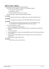
... keys (this is used . Release the Fn + Esc keys after POST. Use the Flash utility to finish loading BIOS Flash, do not boot system. If battery pack does not contain power to update the system BIOS Flash ROM. NOTE: NOTE: Do not install memory related drivers (XMS, EMS, DPMI) when Flash...
... keys (this is used . Release the Fn + Esc keys after POST. Use the Flash utility to finish loading BIOS Flash, do not boot system. If battery pack does not contain power to update the system BIOS Flash ROM. NOTE: NOTE: Do not install memory related drivers (XMS, EMS, DPMI) when Flash...
Acer Aspire V5-531 Notebook Service Guide
Page 75
Press the button to save the changes you made and close the Setup Utility. System Utilities 2-17 Remove the battery pack and DIMM cover. 3. If the prompt appears, repeat steps 4-9 until the BIOS passwords have been cleared. Press F10 to turn on the hardware gap ... conductivity tool to load the system defaults. 11. Press F9 to short the two contacts on the computer. 7. Reinstall the DIMM module, DIMM cover and battery pack. 9. Turn on the two contacts, plug one end of the AC adapter into the DC-in jack and plug one end to access the...
Press the button to save the changes you made and close the Setup Utility. System Utilities 2-17 Remove the battery pack and DIMM cover. 3. If the prompt appears, repeat steps 4-9 until the BIOS passwords have been cleared. Press F10 to turn on the hardware gap ... conductivity tool to load the system defaults. 11. Press F9 to short the two contacts on the computer. 7. Reinstall the DIMM module, DIMM cover and battery pack. 9. Turn on the two contacts, plug one end of the AC adapter into the DC-in jack and plug one end to access the...
Acer Aspire V5-531 Notebook Service Guide
Page 78
... 3-5 Replacement Requirements 3-5 Pre-disassembly Instructions 3-6 Disassembly Process 3-7 External Module Disassembly Process 3-8 External Modules Disassembly Flowchart 3-8 Removing the Battery Pack 3-9 Removing the DIMM Cover 3-10 Removing the DIMM Modules 3-11 Removing the Keyboard 3-12 Removing the ODD Module 3-14 ...WLAN Module 3-27 Removing the Mainboard 3-29 Removing the Thermal Module 3-32 Removing the DC In Module 3-34 Removing the Battery Connector 3-35 Removing the Speaker Module 3-36 Removing the LCD Module 3-38 LCD Module Disassembly Process 3-40 LCD Module ...
... 3-5 Replacement Requirements 3-5 Pre-disassembly Instructions 3-6 Disassembly Process 3-7 External Module Disassembly Process 3-8 External Modules Disassembly Flowchart 3-8 Removing the Battery Pack 3-9 Removing the DIMM Cover 3-10 Removing the DIMM Modules 3-11 Removing the Keyboard 3-12 Removing the ODD Module 3-14 ...WLAN Module 3-27 Removing the Mainboard 3-29 Removing the Thermal Module 3-32 Removing the DC In Module 3-34 Removing the Battery Connector 3-35 Removing the Speaker Module 3-36 Removing the LCD Module 3-38 LCD Module Disassembly Process 3-40 LCD Module ...
Acer Aspire V5-531 Notebook Service Guide
Page 79
... Camera Board 3-51 Reinstalling the LCD Bezel 3-52 Main Unit Reassembly Process 3-53 Reinstalling the LCD Module 3-53 Reinstalling the Speaker Module 3-55 Reinstalling the Battery Connector 3-57 Reinstalling the DC In Module 3-58 Reinstalling the Thermal Module 3-59 Reinstalling the Mainboard 3-61 Reinstalling the WLAN Module 3-64 Reinstalling the HDD... Module Reassembly Process 3-74 Reinstalling the ODD Module 3-74 Reinstalling the Keyboard 3-77 Reinstalling the DIMM Modules 3-79 Reinstalling the DIMM Cover 3-80 Reinstalling the Battery Pack 3-81 3-3
... Camera Board 3-51 Reinstalling the LCD Bezel 3-52 Main Unit Reassembly Process 3-53 Reinstalling the LCD Module 3-53 Reinstalling the Speaker Module 3-55 Reinstalling the Battery Connector 3-57 Reinstalling the DC In Module 3-58 Reinstalling the Thermal Module 3-59 Reinstalling the Mainboard 3-61 Reinstalling the WLAN Module 3-64 Reinstalling the HDD... Module Reassembly Process 3-74 Reinstalling the ODD Module 3-74 Reinstalling the Keyboard 3-77 Reinstalling the DIMM Modules 3-79 Reinstalling the DIMM Cover 3-80 Reinstalling the Battery Pack 3-81 3-3
Acer Aspire V5-531 Notebook Service Guide
Page 84
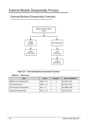
Screw List Step DIMM Cover Disassembly ODD Disassembly ODD Bracket Disassembly Keyboard Disassembly Screw M2.5 x L5 M2.5 × L5 M2 × L3 M2.5 × L5 Quantity 2 1 2 2 Acer Part Number 86.00J51.535 86.00J51.535 86.9A552.3R0 86.00J51.535 3-8 Machine Maintenance External Module Disassembly Process 0 External Modules Disassembly Flowchart 0 REMOVE BATTERY PACK DIMM COVER DIMM MODULES KEYBOARD ODD MODULE ODD BRACKET Figure 3-2. External Modules Disassembly Flowchart Table 3-2.
Screw List Step DIMM Cover Disassembly ODD Disassembly ODD Bracket Disassembly Keyboard Disassembly Screw M2.5 x L5 M2.5 × L5 M2 × L3 M2.5 × L5 Quantity 2 1 2 2 Acer Part Number 86.00J51.535 86.00J51.535 86.9A552.3R0 86.00J51.535 3-8 Machine Maintenance External Module Disassembly Process 0 External Modules Disassembly Flowchart 0 REMOVE BATTERY PACK DIMM COVER DIMM MODULES KEYBOARD ODD MODULE ODD BRACKET Figure 3-2. External Modules Disassembly Flowchart Table 3-2.
Acer Aspire V5-531 Notebook Service Guide
Page 85
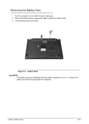
Slide and hold the battery release latch to release the battery pack. 3. Battery Pack NOTE: NOTE: The battery has been highlighted with the yellow rectangle in Figure 3-3. Detach the battery and follow local regulations for disposal. Figure 3-3. Removing the Battery Pack 0 1. Machine Maintenance 3-9 Turn the computer over so that the base is facing up. 2. Lift the battery pack from its bay.
Slide and hold the battery release latch to release the battery pack. 3. Battery Pack NOTE: NOTE: The battery has been highlighted with the yellow rectangle in Figure 3-3. Detach the battery and follow local regulations for disposal. Figure 3-3. Removing the Battery Pack 0 1. Machine Maintenance 3-9 Turn the computer over so that the base is facing up. 2. Lift the battery pack from its bay.
Acer Aspire V5-531 Notebook Service Guide
Page 86
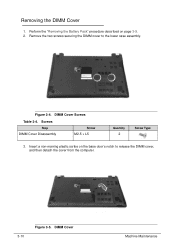
DIMM Cover Screws Table 3-4. Screws Step DIMM Cover Disassembly Screw M2.5 × L5 Quantity 2 Screw Type 3. Remove the two screws securing the DIMM cover to release the DIMM cover, and then detach the cover from the computer. 3-10 Figure 3-5. Insert a non-marring plastic scribe on page 3-9. 2. Perform the "Removing the Battery Pack" procedure described on the base door's notch to the lower case assembly. DIMM Cover Machine Maintenance Removing the DIMM Cover 0 1. Figure 3-4.
DIMM Cover Screws Table 3-4. Screws Step DIMM Cover Disassembly Screw M2.5 × L5 Quantity 2 Screw Type 3. Remove the two screws securing the DIMM cover to release the DIMM cover, and then detach the cover from the computer. 3-10 Figure 3-5. Insert a non-marring plastic scribe on page 3-9. 2. Perform the "Removing the Battery Pack" procedure described on the base door's notch to the lower case assembly. DIMM Cover Machine Maintenance Removing the DIMM Cover 0 1. Figure 3-4.
Acer Aspire V5-531 Notebook Service Guide
Page 88
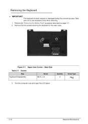
Removing the Keyboard 0 + IMPORTANT: The keyboard is easily warped or damaged during the removal process. Take care not to the lower case. Perform the "Removing the Battery Pack" procedure described on page 3-9. 2. Upper Case Screws - Screws Step Keyboard Disassembly Screw M2.5 × L5 Quantity 2 Screw Type 3. Figure 3-7. Turn the computer over and open the LCD panel. 3-12 Machine Maintenance Remove the two screws securing the keyboard to use excessive force when removing. 1. Base Side Table 3-7.
Removing the Keyboard 0 + IMPORTANT: The keyboard is easily warped or damaged during the removal process. Take care not to the lower case. Perform the "Removing the Battery Pack" procedure described on page 3-9. 2. Upper Case Screws - Screws Step Keyboard Disassembly Screw M2.5 × L5 Quantity 2 Screw Type 3. Figure 3-7. Turn the computer over and open the LCD panel. 3-12 Machine Maintenance Remove the two screws securing the keyboard to use excessive force when removing. 1. Base Side Table 3-7.
Acer Aspire V5-531 Notebook Service Guide
Page 93
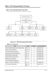
...MODULE MAIN BOARD TOUCHPAD BOARD WLAN BOARD POWER BUTTON BOARD BATTERY CONNECTOR LCD MODULE THERMAL MODULE SPEAKER MODULE DC IN MODULE Figure 3-15. M2 × L3 M2.5 × L5 M2 × 3 Quantity 17 3 3 1 1 4 1 5 2 1 1 Acer Part Number 86.00J51.535 86.00J51.535 86.... Case Disassembly Upper Case Disassembly Touchpad Board Disassembly Power Button Board Disassembly WLAN Module Disassembly Speaker Module Disassembly Mainboard Disassembly Thermal Module Disassembly Battery Connector Disassembly LCD Module Disassembly Screw M2.5 × L5 M2.5 × L5 M2 × L3 M2 × L3 ...
...MODULE MAIN BOARD TOUCHPAD BOARD WLAN BOARD POWER BUTTON BOARD BATTERY CONNECTOR LCD MODULE THERMAL MODULE SPEAKER MODULE DC IN MODULE Figure 3-15. M2 × L3 M2.5 × L5 M2 × 3 Quantity 17 3 3 1 1 4 1 5 2 1 1 Acer Part Number 86.00J51.535 86.00J51.535 86.... Case Disassembly Upper Case Disassembly Touchpad Board Disassembly Power Button Board Disassembly WLAN Module Disassembly Speaker Module Disassembly Mainboard Disassembly Thermal Module Disassembly Battery Connector Disassembly LCD Module Disassembly Screw M2.5 × L5 M2.5 × L5 M2 × L3 M2 × L3 ...


