Acer Aspire V5-531 Notebook Service Guide
Page 6
Removing the HDD Password 2-15 Removing the BIOS Passwords 2-16 Clearing the BIOS Passwords 2-17 LAN EEPROM Utility 2-18 Machine Maintenance 5 Machine Disassembly and Replacement 3-5 Recommended Equipment 3-5 Replacement Requirements 3-5 Pre-disassembly Instructions 3-6 Disassembly Process 3-7 External Module Disassembly Process 3-8 External Modules ...Removing the Touchpad Board 3-21 Removing the Power Button Board 3-23 Removing the SATA Board 3-25 Removing the HDD Module 3-26 Removing the WLAN Module 3-27 Removing the Mainboard 3-29 Removing the Thermal Module 3-32 Removing the...
Removing the HDD Password 2-15 Removing the BIOS Passwords 2-16 Clearing the BIOS Passwords 2-17 LAN EEPROM Utility 2-18 Machine Maintenance 5 Machine Disassembly and Replacement 3-5 Recommended Equipment 3-5 Replacement Requirements 3-5 Pre-disassembly Instructions 3-6 Disassembly Process 3-7 External Module Disassembly Process 3-8 External Modules ...Removing the Touchpad Board 3-21 Removing the Power Button Board 3-23 Removing the SATA Board 3-25 Removing the HDD Module 3-26 Removing the WLAN Module 3-27 Removing the Mainboard 3-29 Removing the Thermal Module 3-32 Removing the...
Acer Aspire V5-531 Notebook Service Guide
Page 78
Machine Disassembly and Replacement 3-5 Recommended Equipment 3-5 Replacement Requirements 3-5 Pre-disassembly Instructions 3-6 Disassembly Process 3-7 External Module Disassembly Process 3-8 External Modules Disassembly Flowchart 3-8 Removing the Battery Pack 3-9 Removing the DIMM Cover...the Palmrest Module/Upper Case 3-18 Removing the Touchpad Board 3-21 Removing the Power Button Board 3-23 Removing the SATA Board 3-25 Removing the HDD Module 3-26 Removing the WLAN Module 3-27 Removing the Mainboard 3-29 Removing the Thermal Module 3-32 Removing the DC In Module 3-34 Removing...
Machine Disassembly and Replacement 3-5 Recommended Equipment 3-5 Replacement Requirements 3-5 Pre-disassembly Instructions 3-6 Disassembly Process 3-7 External Module Disassembly Process 3-8 External Modules Disassembly Flowchart 3-8 Removing the Battery Pack 3-9 Removing the DIMM Cover...the Palmrest Module/Upper Case 3-18 Removing the Touchpad Board 3-21 Removing the Power Button Board 3-23 Removing the SATA Board 3-25 Removing the HDD Module 3-26 Removing the WLAN Module 3-27 Removing the Mainboard 3-29 Removing the Thermal Module 3-32 Removing the DC In Module 3-34 Removing...
Acer Aspire V5-531 Notebook Service Guide
Page 164
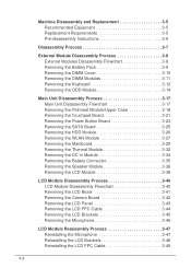
... Troubleshooting Refer to the desired resolution. Click Apply and check the display. If the display is faulty and should be replaced. Readjust if necessary. 4. There are no red Xs or yellow exclamation marks There are no device conflicts ... internal display and the external display by removing the power cable and the battery pack. Start the computer. Perform the "Reinstalling the HDD Module" and "Reinstalling the ODD Module" procedures described on page 4-7. 7. Adjust the brightness to determine that the computer is not ...
... Troubleshooting Refer to the desired resolution. Click Apply and check the display. If the display is faulty and should be replaced. Readjust if necessary. 4. There are no red Xs or yellow exclamation marks There are no device conflicts ... internal display and the external display by removing the power cable and the battery pack. Start the computer. Perform the "Reinstalling the HDD Module" and "Reinstalling the ODD Module" procedures described on page 4-7. 7. Adjust the brightness to determine that the computer is not ...
Acer Aspire V5-531 Notebook Service Guide
Page 203
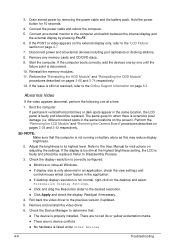
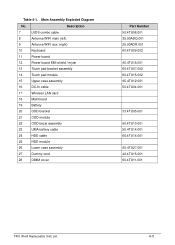
... cable 17 Wireless LAN card 18 Mainboard 19 Battery 20 ODD bracket 21 ODD module 22 ODD bezel assembly 23 UMA battery cable 24 HDD cable 25 HDD module 26 Lower case assembly 27 Dummy card 28 DIMM cover Part Number 50.4TU08.001 25.90ADQ.001 25.90ADR.001 60.4TU09....4TU04.001 33.4TU05.001 60.4TU10.001 50.4TU14.001 65.4TU14.001 60.4TU27.001 42.4TU15.001 60.4TU11.001 FRU (Field Replaceable Unit) List 6-5 Main Assembly Exploded Diagram No.
... cable 17 Wireless LAN card 18 Mainboard 19 Battery 20 ODD bracket 21 ODD module 22 ODD bezel assembly 23 UMA battery cable 24 HDD cable 25 HDD module 26 Lower case assembly 27 Dummy card 28 DIMM cover Part Number 50.4TU08.001 25.90ADQ.001 25.90ADR.001 60.4TU09....4TU04.001 33.4TU05.001 60.4TU10.001 50.4TU14.001 65.4TU14.001 60.4TU27.001 42.4TU15.001 60.4TU11.001 FRU (Field Replaceable Unit) List 6-5 Main Assembly Exploded Diagram No.


