Service Guide
Page 7
Table of Contents System Specifications 1 Features 1 System Block Diagram 3 Your Acer Notebook tour 4 Front View 4 Closed Front View 5 Left View 5 Right View 6 Rear View 6 Bottom View 7 Indicators 7 TouchPad Basics 8 Using the Keyboard 9 Lock ...Information 33 General Information 34 Pre-disassembly Instructions 34 Disassembly Process 34 External Module Disassembly Process 35 External Modules Disassembly Flowchart 35 Removing the Battery Pack 36 Removing the 3G Cover 37 Removing the Keyboard 38 Removing the Upper and Lower Covers 39 LCD Module Disassembly Process 41 LCD...
Table of Contents System Specifications 1 Features 1 System Block Diagram 3 Your Acer Notebook tour 4 Front View 4 Closed Front View 5 Left View 5 Right View 6 Rear View 6 Bottom View 7 Indicators 7 TouchPad Basics 8 Using the Keyboard 9 Lock ...Information 33 General Information 34 Pre-disassembly Instructions 34 Disassembly Process 34 External Module Disassembly Process 35 External Modules Disassembly Flowchart 35 Removing the Battery Pack 36 Removing the 3G Cover 37 Removing the Keyboard 38 Removing the Upper and Lower Covers 39 LCD Module Disassembly Process 41 LCD...
Service Guide
Page 8
... the WLAN Board 73 Replacing the LCM Module 73 Replacing the Upper Cover 75 Replacing the Keyboard 76 Replacing the 3G cover 77 Replacing the Battery 77 Troubleshooting 79 Common Problems 79 Power On Issue 80 No Display Issue 81 Random Loss of BIOS Settings 83 LCD Failure 84 Built-In...
... the WLAN Board 73 Replacing the LCM Module 73 Replacing the Upper Cover 75 Replacing the Keyboard 76 Replacing the 3G cover 77 Replacing the Battery 77 Troubleshooting 79 Common Problems 79 Power On Issue 80 No Display Issue 81 Random Loss of BIOS Settings 83 LCD Failure 84 Built-In...

Service Guide
Page 16
... headphones). Note: Push to USB 2.0 devices (e.g. Connect to remove/install the card. No. 1 Icon Item Battery bay Description Houses the computer's battery pack. 6 Chapter 1 Accepts Secure Digital (SD), MultiMediaCard (MMC), Memory Stick (MS), Memory Stick PRO (...MS PRO), xD-Picture Card (xD). Connects to a Kensington-compatible computer security lock. Headphones/ speaker/line-out jack USB 2.0 ports Multi-in jack Accepts input from external microphones. Only one...
... headphones). Note: Push to USB 2.0 devices (e.g. Connect to remove/install the card. No. 1 Icon Item Battery bay Description Houses the computer's battery pack. 6 Chapter 1 Accepts Secure Digital (SD), MultiMediaCard (MMC), Memory Stick (MS), Memory Stick PRO (...MS PRO), xD-Picture Card (xD). Connects to a Kensington-compatible computer security lock. Headphones/ speaker/line-out jack USB 2.0 ports Multi-in jack Accepts input from external microphones. Only one...

Service Guide
Page 17
...shows green when in position. Indicators The computer has several easy-to pass through the casing unhindered. Icon Function Battery Description Indicates the computer's battery status. NOTE: 1. Chapter 1 7 Num Lock Caps Lock Lights up when Caps Lock is activated. HDD ... grills allow audio to -read status indicators. Bottom View No. 1 Icon Item Battery bay Description Houses the computer's battery pack. 2 Battery lock Locks the battery in AC mode. Battery release latch Releases the battery for removal. 3 Ventilation slots • Vents enable the computer to stay cool,...
...shows green when in position. Indicators The computer has several easy-to pass through the casing unhindered. Icon Function Battery Description Indicates the computer's battery status. NOTE: 1. Chapter 1 7 Num Lock Caps Lock Lights up when Caps Lock is activated. HDD ... grills allow audio to -read status indicators. Bottom View No. 1 Icon Item Battery bay Description Houses the computer's battery pack. 2 Battery lock Locks the battery in AC mode. Battery release latch Releases the battery for removal. 3 Ventilation slots • Vents enable the computer to stay cool,...

Service Guide
Page 27
... Type Features Item Specification • 3G card in mini-PCI card size • Control by USB interface • User accessible SIM card by battery remove • Antenna: Has to be placed on the sides of LCD in A/B cover Wireless LAN Type Features Item... Battery Item Vendor & model name Battery Type Pack capacity Number of battery cell Package configuration Specification Foxconn FOX_ATH_XB63 Foxconn Atheros XB63 • Manufacturing option: mini-card • 802.11b/g (3rd Party) •...
... Type Features Item Specification • 3G card in mini-PCI card size • Control by USB interface • User accessible SIM card by battery remove • Antenna: Has to be placed on the sides of LCD in A/B cover Wireless LAN Type Features Item... Battery Item Vendor & model name Battery Type Pack capacity Number of battery cell Package configuration Specification Foxconn FOX_ATH_XB63 Foxconn Atheros XB63 • Manufacturing option: mini-card • 802.11b/g (3rd Party) •...
Service Guide
Page 37
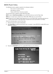
... Memory). Press F2 during boot to finish BIOS flash, the system will not boot as USB HDD) before you use the Flash Utility: 1. If the battery pack does not contain enough power to enter the Setup Menu. 2. Chapter 2 27
... Memory). Press F2 during boot to finish BIOS flash, the system will not boot as USB HDD) before you use the Flash Utility: 1. If the battery pack does not contain enough power to enter the Setup Menu. 2. Chapter 2 27

Service Guide
Page 44
... flowcharts provided in the succeeding disassembly sections illustrate the entire disassembly sequence. For example, if you want to any of the hardware components. Remove the battery pack. General Information Pre-disassembly Instructions Before proceeding with the disassembly procedure, make sure that order. Unplug the AC adapter and all peripherals. 2.
... flowcharts provided in the succeeding disassembly sections illustrate the entire disassembly sequence. For example, if you want to any of the hardware components. Remove the battery pack. General Information Pre-disassembly Instructions Before proceeding with the disassembly procedure, make sure that order. Unplug the AC adapter and all peripherals. 2.
Service Guide
Page 46
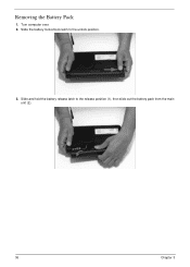
Slide the battery lock/unlock latch to the release position (1), then slide out the battery pack from the main unit (2). 1 2 36 Chapter 3 Removing the Battery Pack 1. Turn computer over. 2. Slide and hold the battery release latch to the unlock position. 3.
Slide the battery lock/unlock latch to the release position (1), then slide out the battery pack from the main unit (2). 1 2 36 Chapter 3 Removing the Battery Pack 1. Turn computer over. 2. Slide and hold the battery release latch to the unlock position. 3.
Service Guide
Page 47
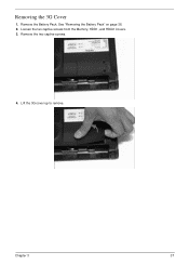
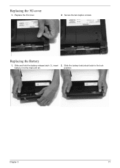
See "Removing the Battery Pack" on page 36. 2. Remove the two captive screws. 4. Chapter 3 37 Removing the 3G Cover 1. Loosen the ten captive screws from the Memory, HDD1, and HDD2 Covers. 3. Lift the 3G cover up to remove. Remove the Battery Pack.
See "Removing the Battery Pack" on page 36. 2. Remove the two captive screws. 4. Chapter 3 37 Removing the 3G Cover 1. Loosen the ten captive screws from the Memory, HDD1, and HDD2 Covers. 3. Lift the 3G cover up to remove. Remove the Battery Pack.
Service Guide
Page 49
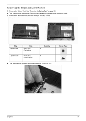
Removing the Upper and Lower Covers 1. See "Removing the Battery Pack" on page 36. 2. Screw Type Chapter 3 39 Remove the two rubber foot pads and the eight securing screws. Remove the Battery Pack. Remove the three securing screws under the battery pack. 3. Step Upper Cover Upper Cover Size M2*3 (NL) Red callout M2*5 (NL) Green callout Quantity 3 5 4. Turn the computer upside down. Turn the computer rightside up and disconnect the TouchPad FFC.
Removing the Upper and Lower Covers 1. See "Removing the Battery Pack" on page 36. 2. Screw Type Chapter 3 39 Remove the two rubber foot pads and the eight securing screws. Remove the Battery Pack. Remove the three securing screws under the battery pack. 3. Step Upper Cover Upper Cover Size M2*3 (NL) Red callout M2*5 (NL) Green callout Quantity 3 5 4. Turn the computer upside down. Turn the computer rightside up and disconnect the TouchPad FFC.
Service Guide
Page 61
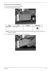
Chapter 3 51 Remove the securing screw as shown. Removing the WLAN Module 1. Step WLAN Module Size M2*3 (NL) Quantity 1 Screw Type NOTE: The antenna cables were removed during the LCD module disassembly. Remove it from the mainboard as shown. The module pops up. See "Removing the LCD Module" on page 36. 2. See "Removing the Battery Pack" on page 42. 3.
Chapter 3 51 Remove the securing screw as shown. Removing the WLAN Module 1. Step WLAN Module Size M2*3 (NL) Quantity 1 Screw Type NOTE: The antenna cables were removed during the LCD module disassembly. Remove it from the mainboard as shown. The module pops up. See "Removing the LCD Module" on page 36. 2. See "Removing the Battery Pack" on page 42. 3.
Service Guide
Page 87
Replacing the Battery 1. position. 1 2 Chapter 3 77 Replace the 3G cover. 2. Slide the battery lock/unlock latch to the lock battery in to the main unit (2). Slide and hold the battery release latch (1), insert 2. Replacing the 3G cover 1. Secure the two captive screws.
Replacing the Battery 1. position. 1 2 Chapter 3 77 Replace the 3G cover. 2. Slide the battery lock/unlock latch to the lock battery in to the main unit (2). Slide and hold the battery release latch (1), insert 2. Replacing the 3G cover 1. Secure the two captive screws.
Service Guide
Page 92
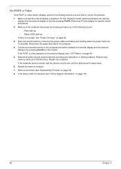
.../DVD discs. Disconnect power and all external devices including port replicators or docking stations. If the computer boots correctly, add the devices one by one at least one of the following actions one until the failure point is still not resolved, see "Disassembly Process" on page 84. 5. Connect an external monitor to correct the... LEDs light up If there is selected. Reference Product pages for 10 seconds. Make sure the computer has power by removing the power cable and battery and holding down the power button for specific model procedures. 2.
.../DVD discs. Disconnect power and all external devices including port replicators or docking stations. If the computer boots correctly, add the devices one by one at least one of the following actions one until the failure point is still not resolved, see "Disassembly Process" on page 84. 5. Connect an external monitor to correct the... LEDs light up If there is selected. Reference Product pages for 10 seconds. Make sure the computer has power by removing the power cable and battery and holding down the power button for specific model procedures. 2.
Service Guide
Page 93
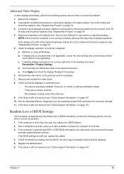
... and control/mouse wheel zoom feature in the same location, the LCD is present (different colored spots in the same locations on battery alone as this may be defective and should be replaced. Reboot the computer. 2. d. Check the Device Manager to correct the problem... 34. 4. b. Adjust the brightness to the desired resolution. e. Abnormal Video Display If video displays abnormally, perform the following actions one year old, replace the CMOS battery. 2. See "Disassembly Process" on page 34. 3. If the BIOS settings are no device conflicts. • No hardware is ...
... and control/mouse wheel zoom feature in the same location, the LCD is present (different colored spots in the same locations on battery alone as this may be defective and should be replaced. Reboot the computer. 2. d. Check the Device Manager to correct the problem... 34. 4. b. Adjust the brightness to the desired resolution. e. Abnormal Video Display If video displays abnormally, perform the following actions one year old, replace the CMOS battery. 2. See "Disassembly Process" on page 34. 3. If the BIOS settings are no device conflicts. • No hardware is ...
Service Guide
Page 100
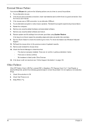
...log for errors. Do not replace a non-defective FRUs: 1. Swap M/B to correct the problem. If the mouse uses a wireless connection, insert new batteries and confirm there is ok. 3. Other Failures If the CRT Switch, Dock, LAN Port, external MIC or Speakers, PCI Express Card, 5-in-1 Card... Reader or Volume Wheel fail, perform the following actions one at a time to correct the problem. 1. Check Drive whether is properly installed. Remove any recently added hardware and associated software. 7. External Mouse...
...log for errors. Do not replace a non-defective FRUs: 1. Swap M/B to correct the problem. If the mouse uses a wireless connection, insert new batteries and confirm there is ok. 3. Other Failures If the CRT Switch, Dock, LAN Port, external MIC or Speakers, PCI Express Card, 5-in-1 Card... Reader or Volume Wheel fail, perform the following actions one at a time to correct the problem. 1. Check Drive whether is properly installed. Remove any recently added hardware and associated software. 7. External Mouse...
Service Guide
Page 101
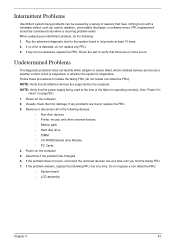
... at a time until you find the failing FRU. 7. If the problem remains, replace the following devices: • Non-Acer devices • Printer, mouse, and other external devices • Battery pack • Hard disk drive • DIMM • CD-ROM/Diskette drive Module • PC Cards 4. If no... FRU. 3. Remove or disconnect all attached devices are supported by a variety of the following FRU one at least 10 times. 2. If the problem does not recur, reconnect the removed devices one at the time of the failure is detected, replace the FRU. Power-on page 80): 1. ...
... at a time until you find the failing FRU. 7. If the problem remains, replace the following devices: • Non-Acer devices • Printer, mouse, and other external devices • Battery pack • Hard disk drive • DIMM • CD-ROM/Diskette drive Module • PC Cards 4. If no... FRU. 3. Remove or disconnect all attached devices are supported by a variety of the following FRU one at least 10 times. 2. If the problem does not recur, reconnect the removed devices one at the time of the failure is detected, replace the FRU. Power-on page 80): 1. ...
Service Guide
Page 123
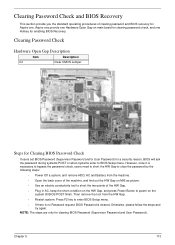
... on M/B as picture. • Use an electric conductivity tool to short the two points of clearing password and BIOS recovery for Aspire one Hardware Open Gap on the system till BIOS POST finish. Press F2 key to BIOS Setup menu. Clearing Password Check Hardware Open Gap...steps: • Power Off a system, and remove HDD, AC and Battery from the HW Gap. • Restart system. Chapter 5 113 NOTE: The steps are only for clearing BIOS Password (Supervisor Password and User Password). Aspire one provide one . However, once it is cleared. Otherwise, please follow the steps and...
... on M/B as picture. • Use an electric conductivity tool to short the two points of clearing password and BIOS recovery for Aspire one Hardware Open Gap on the system till BIOS POST finish. Press F2 key to BIOS Setup menu. Clearing Password Check Hardware Open Gap...steps: • Power Off a system, and remove HDD, AC and Battery from the HW Gap. • Restart system. Chapter 5 113 NOTE: The steps are only for clearing BIOS Password (Supervisor Password and User Password). Aspire one provide one . However, once it is cleared. Otherwise, please follow the steps and...
Service Guide
Page 124
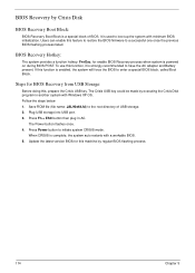
...Crisis USB key could be made by executing the Crisis Disk program in AC. Save ROM file (file name: JAL90x64.fd) to a successful one once the previous BIOS flashing process failed. Press Fn + ESC button then plug in another system with Windows XP OS. The Power button flashes.... Plug USB storage into USB port. 3. When CRISIS is a special block of USB storage. 2. Press Power button to have the AC adapter and Battery present. Follow the steps below: 1. To use this , prepare the Crisis USB key. BIOS Recovery by regular BIOS flashing process. 114 Chapter 5 BIOS...
...Crisis USB key could be made by executing the Crisis Disk program in AC. Save ROM file (file name: JAL90x64.fd) to a successful one once the previous BIOS flashing process failed. Press Fn + ESC button then plug in another system with Windows XP OS. The Power button flashes.... Plug USB storage into USB port. 3. When CRISIS is a special block of USB storage. 2. Press Power button to have the AC adapter and Battery present. Follow the steps below: 1. To use this , prepare the Crisis USB key. BIOS Recovery by regular BIOS flashing process. 114 Chapter 5 BIOS...

Service Guide
Page 128
Aspire one FRU List Category Adapter Battery Board Description ADAPTER LITE-ON 30W 1.7X5.5X11 BLACK PA-1300-04AC LF BATTERY SIMPLO UM-2008AW LI-ION 3S1P PANASONIC 3 CELL 2200MAH MAIN COMMON MACLES / WHITE BATTERY SIMPLO UM-2008A LI-ION 3S1P SAMSUNG 3 CELL 4400MAH MAIN COMMON MACLES BATTERY SIMPLO UM-2008A LI-...ION 3S1P SAMSUNG 3 CELL 4800MAH MAIN COMMON MACLES Battery SIMPLO UM-2008AW Li-Ion 3S1P SAMSUNG 3 cell 2200mAh Main COMMON Macles / White Battery SIMPLO UM-2008A Li-Ion 3S1P PANASONIC 3 cell 4400mAh Main COMMON Macles Battery SIMPLO UM-2008B Li-Ion 3S2P PANASONIC 6 cell 5200mAh ...
Aspire one FRU List Category Adapter Battery Board Description ADAPTER LITE-ON 30W 1.7X5.5X11 BLACK PA-1300-04AC LF BATTERY SIMPLO UM-2008AW LI-ION 3S1P PANASONIC 3 CELL 2200MAH MAIN COMMON MACLES / WHITE BATTERY SIMPLO UM-2008A LI-ION 3S1P SAMSUNG 3 CELL 4400MAH MAIN COMMON MACLES BATTERY SIMPLO UM-2008A LI-...ION 3S1P SAMSUNG 3 CELL 4800MAH MAIN COMMON MACLES Battery SIMPLO UM-2008AW Li-Ion 3S1P SAMSUNG 3 cell 2200mAh Main COMMON Macles / White Battery SIMPLO UM-2008A Li-Ion 3S1P PANASONIC 3 cell 4400mAh Main COMMON Macles Battery SIMPLO UM-2008B Li-Ion 3S2P PANASONIC 6 cell 5200mAh ...

Service Guide
Page 168
... NB Chipset Intel CS QG82945GSE MM#897840 ICH7M Antivirus application McAfee UMA PIFA Foxconn FOX_ATH_XB63 Foxconn Atheros XB63 minicard b/g Aspire one White Testing Information Vendor 2nd Battery Test 60001535 PANASONIC Cover Test 9999995 ONE TIME VENDER Accessory Test 10001028 QUANTA Adapter Test 10001081 DELTA 60003544 LITE-ON OPT 60002015 HIPRO Type 6CELL2.6 White IMR...
... NB Chipset Intel CS QG82945GSE MM#897840 ICH7M Antivirus application McAfee UMA PIFA Foxconn FOX_ATH_XB63 Foxconn Atheros XB63 minicard b/g Aspire one White Testing Information Vendor 2nd Battery Test 60001535 PANASONIC Cover Test 9999995 ONE TIME VENDER Accessory Test 10001028 QUANTA Adapter Test 10001081 DELTA 60003544 LITE-ON OPT 60002015 HIPRO Type 6CELL2.6 White IMR...


