Acer Aspire M3985 Desktop Service Guide
Page 8
System Troubleshooting 76 Hardware Diagnostic Procedure 76 System Check Procedures 77 Power System Check 77 System External Inspection 77 System Internal Inspection 77 Beep Codes 78 Checkpoints 79 BIOS Recovery 82 Jumper and Connector Information 85 M/B Placement 85 Jumper Setting 87 Internal header pin definition 90 Connector pin definition 93 FRU (Field Replaceable Unit) List 98 Aspire M3985 Exploded Diagram 99 Aspire M3985 FRU List 101 viii
System Troubleshooting 76 Hardware Diagnostic Procedure 76 System Check Procedures 77 Power System Check 77 System External Inspection 77 System Internal Inspection 77 Beep Codes 78 Checkpoints 79 BIOS Recovery 82 Jumper and Connector Information 85 M/B Placement 85 Jumper Setting 87 Internal header pin definition 90 Connector pin definition 93 FRU (Field Replaceable Unit) List 98 Aspire M3985 Exploded Diagram 99 Aspire M3985 FRU List 101 viii
Acer Aspire M3985 Desktop Service Guide
Page 12
System BIOS • Type: Use SPI Flash • System BIOS: 8MB • Kernel: AMI Kernel with Acer skin Power supply • Non PFC 300W / PFC 300W /FR 300W. • Support models are listed on AVLC. 4 Chapter 1
System BIOS • Type: Use SPI Flash • System BIOS: 8MB • Kernel: AMI Kernel with Acer skin Power supply • Non PFC 300W / PFC 300W /FR 300W. • Support models are listed on AVLC. 4 Chapter 1
Acer Aspire M3985 Desktop Service Guide
Page 16
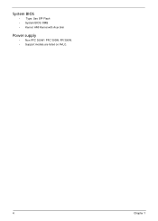
... Socket Type LGA1155 Minimum operating speed 0 MHz (If Stop CPU Clock in Sleep State in BIOS Setup is set to Enabled.) BIOS Item Specification BIOS code programer AMI Kernel with Acer skin BIOS version P01-A0 BIOS ROM type SPI Flash BIOS ROM size 8Mb Support protocol SMBIOS(DMI)2.4/DMI2.0 Device Boot Support 1st priority: SATA HDD...
... Socket Type LGA1155 Minimum operating speed 0 MHz (If Stop CPU Clock in Sleep State in BIOS Setup is set to Enabled.) BIOS Item Specification BIOS code programer AMI Kernel with Acer skin BIOS version P01-A0 BIOS ROM type SPI Flash BIOS ROM size 8Mb Support protocol SMBIOS(DMI)2.4/DMI2.0 Device Boot Support 1st priority: SATA HDD...
Acer Aspire M3985 Desktop Service Guide
Page 18
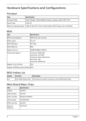
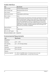
... Music synthesizer Sampling rate MPU-401 UART support Microphone/Headphone jack Specification Intel PCH Panther Point B75 REALTEK/ALC662-VD0-GR codec 5.1 Enable/disable by BIOS Setup Stereo ALC662-VD meets audio performance and function requirements for multimedia PCs and ultra mobile devices.
... Music synthesizer Sampling rate MPU-401 UART support Microphone/Headphone jack Specification Intel PCH Panther Point B75 REALTEK/ALC662-VD0-GR codec 5.1 Enable/disable by BIOS Setup Stereo ALC662-VD meets audio performance and function requirements for multimedia PCs and ultra mobile devices.
Acer Aspire M3985 Desktop Service Guide
Page 21
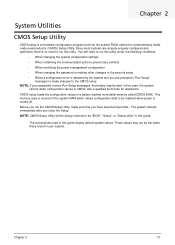
.... CMOS setup loads the configuration values in your system. This memory area is not part of the system RAM which allows configuration data to as "BIOS", "Setup", or "Setup utility" in CMOS. You will be simply referred to be the same those found in a battery-backed nonvolatile memory called the complementary...
.... CMOS setup loads the configuration values in your system. This memory area is not part of the system RAM which allows configuration data to as "BIOS", "Setup", or "Setup utility" in CMOS. You will be simply referred to be the same those found in a battery-backed nonvolatile memory called the complementary...
Acer Aspire M3985 Desktop Service Guide
Page 23
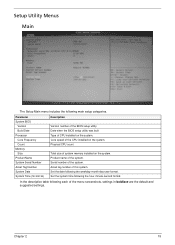
...main setup categories. Serial number of system memory installed on the system. Asset tag number of CPU installed on the system. Date when the BIOS setup utility was built Type of this system. Set the system time following each of the CPU installed on the system. Chapter 2 15 ...Name System Serial Number Asset Tag Number System Date System Time (hh:mm:ss) Description Version number of the system. Product name of the BIOS setup utility. In the descriptive table following the hour-minute-second format. Core speed of the menu screenshots, settings in boldface are the ...
...main setup categories. Serial number of system memory installed on the system. Asset tag number of CPU installed on the system. Date when the BIOS setup utility was built Type of this system. Set the system time following each of the CPU installed on the system. Chapter 2 15 ...Name System Serial Number Asset Tag Number System Date System Time (hh:mm:ss) Description Version number of the system. Product name of the BIOS setup utility. In the descriptive table following the hour-minute-second format. Core speed of the menu screenshots, settings in boldface are the ...
Acer Aspire M3985 Desktop Service Guide
Page 25
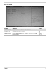
Selects power on state for Num Lock. Option On Off Enabled Disabled Chapter 2 17 Miscellaneous Parameter AHCI Port0/1/2/3/4/5 Bootup Num-lock Description Displays the status of auto detection of the AHCI device. USB Beep Message Enables or disables BIOS to display error beeps or messages during USB device enumeration.
Selects power on state for Num Lock. Option On Off Enabled Disabled Chapter 2 17 Miscellaneous Parameter AHCI Port0/1/2/3/4/5 Bootup Num-lock Description Displays the status of auto detection of the AHCI device. USB Beep Message Enables or disables BIOS to display error beeps or messages during USB device enumeration.
Acer Aspire M3985 Desktop Service Guide
Page 31
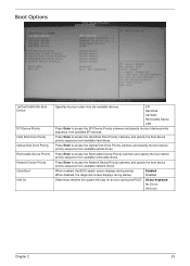
... during startup. Press Enter to access the Removable Device Priority submenu and specify the boot device priority sequence from available optical drives. When enabled, the BIOS splash screen displays during the POST. EFI Hard Disk CD^DVD Removable Device LAN Press Enter to access the EFI Device Priority submenu and specify...
... during startup. Press Enter to access the Removable Device Priority submenu and specify the boot device priority sequence from available optical drives. When enabled, the BIOS splash screen displays during the POST. EFI Hard Disk CD^DVD Removable Device LAN Press Enter to access the EFI Device Priority submenu and specify...
Acer Aspire M3985 Desktop Service Guide
Page 32
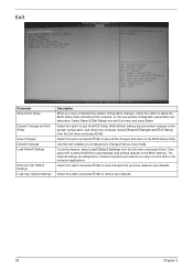
...changes, select this option to the system configuration, and reboot the computer. Select this option and press Enter to the BIOS settings. Select this option to quit the BIOS Setup Utility without making any changes that you have made . To set this feature, select Load Default Settings from the...Changes and Exit Setup from the Exit menu and press Enter. Use this item enables you to discard any permanent changes to leave the BIOS Setup Utility and reboot the computer, so the new system configuration parameters can take effect. Exit Parameter Save & Exit Setup Discard Changes and...
...changes, select this option to the system configuration, and reboot the computer. Select this option and press Enter to the BIOS settings. Select this option to quit the BIOS Setup Utility without making any changes that you have made . To set this feature, select Load Default Settings from the...Changes and Exit Setup from the Exit menu and press Enter. Use this item enables you to discard any permanent changes to leave the BIOS Setup Utility and reboot the computer, so the new system configuration parameters can take effect. Exit Parameter Save & Exit Setup Discard Changes and...
Acer Aspire M3985 Desktop Service Guide
Page 85
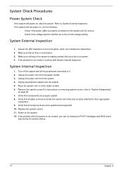
... it. 2. Unplug the power cord from the power outlets. 3. Place the system unit on the front panel, which can try viewing the POST messages and BIOS event logs during the system startup. 77 Chapter 4 Make sure nothing in the system is not evident, you can indicate the malfunction. 2. Verify that all... Disassembly" on page 25. 7. Inspect the LED indicators on a flat, stable surface. 6. System External Inspection 1. Unplug all components are properly seated. 8. Verify that components are Acer-qualified and supported. 10. System Internal Inspection 1.
... it. 2. Unplug the power cord from the power outlets. 3. Place the system unit on the front panel, which can try viewing the POST messages and BIOS event logs during the system startup. 77 Chapter 4 Make sure nothing in the system is not evident, you can indicate the malfunction. 2. Verify that all... Disassembly" on page 25. 7. Inspect the LED indicators on a flat, stable surface. 6. System External Inspection 1. Unplug all components are properly seated. 8. Verify that components are Acer-qualified and supported. 10. System Internal Inspection 1.
Acer Aspire M3985 Desktop Service Guide
Page 86
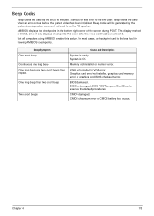
... is ready. VGA not installed or VGA error. CMOS checksum error or CMOS battery loss occurs. Chapter 4 78 Beep codes will be generated by the BIOS to indicate a serious or fatal error to the end user. Memory not installed or memory error. Beep codes are used when an error occurs before... the system video has been initialized. BIOS is limited, since it only displays checkpoints that occur after the video card has been activated. This display method is damaged...
... is ready. VGA not installed or VGA error. CMOS checksum error or CMOS battery loss occurs. Chapter 4 78 Beep codes will be generated by the BIOS to indicate a serious or fatal error to the end user. Memory not installed or memory error. Beep codes are used when an error occurs before... the system video has been initialized. BIOS is limited, since it only displays checkpoints that occur after the video card has been activated. This display method is damaged...
Acer Aspire M3985 Desktop Service Guide
Page 87
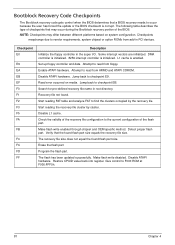
...after the video card has been activated. CPUID information is necessary,control flows to checkpoint E0. Leaves all checkpoints generated by the BIOS requires acheckpoint card, also referred to as -RAM functionality is enabled at this point. The following table describes the type of I/O... keyboard controller BAT test. Verify that checkpoints may occur during POST. Test base 512KB memory. Early super I /O port 80h.The BIOS outputs checkpoints throughout bootblock and Power-On Self Test (POST) to indicate the task the system is currently executing. Checkpoint sare very useful...
...after the video card has been activated. CPUID information is necessary,control flows to checkpoint E0. Leaves all checkpoints generated by the BIOS requires acheckpoint card, also referred to as -RAM functionality is enabled at this point. The following table describes the type of I/O... keyboard controller BAT test. Verify that checkpoints may occur during POST. Test base 512KB memory. Early super I /O port 80h.The BIOS outputs checkpoints throughout bootblock and Power-On Self Test (POST) to indicate the task the system is currently executing. Checkpoint sare very useful...

Acer Aspire M3985 Desktop Service Guide
Page 88
Give control to the next. OEM memory detection/configuration error. This range is waking from one platform to BIOS POST (ExecutePOSTKernel). Chapter 4 80 See POST Code Checkpoints section of document for chipset vendors & system manufacturers. Checkpoint DA DC E1-E8 ECEE Description Restore CPUID value back into register. System is reserved for more information. The error associated with this value may be different from ACPI S3 state.
Give control to the next. OEM memory detection/configuration error. This range is waking from one platform to BIOS POST (ExecutePOSTKernel). Chapter 4 80 See POST Code Checkpoints section of document for chipset vendors & system manufacturers. Checkpoint DA DC E1-E8 ECEE Description Restore CPUID value back into register. System is reserved for more information. The error associated with this value may be different from ACPI S3 state.
Acer Aspire M3985 Desktop Service Guide
Page 89
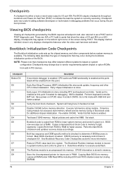
...following table describes the type of the recovery file configuration to read from floppy. Attempt to the current configuration of the BIOS. Read error occurred on system configuration. L1 cache is initialized. Enable ATAPI hardware. Disable ATAPI hardware. Some interrupt ...write enabled through chipset and OEM specific method. Bootblock Recovery Code Checkpoints The Bootblock recovery code gets control when the BIOS determines that a BIOS recovery needs to checkpoint E9. DMA controller is initialized. 8259 interrupt controller is enabled. Set up floppy controller ...
...following table describes the type of the recovery file configuration to read from floppy. Attempt to the current configuration of the BIOS. Read error occurred on system configuration. L1 cache is initialized. Enable ATAPI hardware. Disable ATAPI hardware. Some interrupt ...write enabled through chipset and OEM specific method. Bootblock Recovery Code Checkpoints The Bootblock recovery code gets control when the BIOS determines that a BIOS recovery needs to checkpoint E9. DMA controller is initialized. 8259 interrupt controller is enabled. Set up floppy controller ...
Acer Aspire M3985 Desktop Service Guide
Page 90
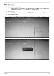
Before recovering BIOS, please change "Reset NVRAM" item form "Enabled" to USB Thumb drive. 2. BIOS Recovery 1. Recovery Menu and Step: a. The usage of recovery boot block: • Please re-name BIOS ROM (xxxx.ROM or 2MB size ROM) file to "AMIBOOT.ROM" and burn in BIOS ROM file to CDROM or copy BIOS ROM file to "Disabled". Automatic mode: • When BIOS flash crashed, using recovery CDROM/USB Thumb drive to recover BIOS. 3. Chapter 4 82
Before recovering BIOS, please change "Reset NVRAM" item form "Enabled" to USB Thumb drive. 2. BIOS Recovery 1. Recovery Menu and Step: a. The usage of recovery boot block: • Please re-name BIOS ROM (xxxx.ROM or 2MB size ROM) file to "AMIBOOT.ROM" and burn in BIOS ROM file to CDROM or copy BIOS ROM file to "Disabled". Automatic mode: • When BIOS flash crashed, using recovery CDROM/USB Thumb drive to recover BIOS. 3. Chapter 4 82

Acer Aspire M3985 Desktop Service Guide
Page 94
No Label 7 SATA1~5 9 BIOS_WP 11 F_SSUSB1 13 PCIE_X16 Description No Serial ATA Gen2 8 connectors BIOS write protect 10 header Front panel USB3 12 header PCI Express x16 slot 14 Label SATA0 F_USB1~2 PCIE_X1_1~3 F_AUDIO 15 SYS_FAN1 System fan connector 17 FLASH_OVE Flash override RRIDE header 19 J129 Board ID header 16 ATX_CPU 18 TPM 20 J128 Description Serial ATA Gen3 connector Front panel USB2 headers PCI Express x1 slot Front panel audio header Auxiliary 4-pin power connector TPM header Board ID header 86 Chapter 5
No Label 7 SATA1~5 9 BIOS_WP 11 F_SSUSB1 13 PCIE_X16 Description No Serial ATA Gen2 8 connectors BIOS write protect 10 header Front panel USB3 12 header PCI Express x16 slot 14 Label SATA0 F_USB1~2 PCIE_X1_1~3 F_AUDIO 15 SYS_FAN1 System fan connector 17 FLASH_OVE Flash override RRIDE header 19 J129 Board ID header 16 ATX_CPU 18 TPM 20 J128 Description Serial ATA Gen3 connector Front panel USB2 headers PCI Express x1 slot Front panel audio header Auxiliary 4-pin power connector TPM header Board ID header 86 Chapter 5

Acer Aspire M3985 Desktop Service Guide
Page 97
Place the jumper cap on pins 2 and 3 to Enable Protection. Jumper E51 Type 3-pin Description BIOS write Protection Setting (default) 1-2: Enable 2-3: Disable(default) Chapter 5 89 The following table shows the settings of the 3-pin E51 jumper. Place the jumper cap on pins 1 and 2 to Disable Protection.
Place the jumper cap on pins 2 and 3 to Enable Protection. Jumper E51 Type 3-pin Description BIOS write Protection Setting (default) 1-2: Enable 2-3: Disable(default) Chapter 5 89 The following table shows the settings of the 3-pin E51 jumper. Place the jumper cap on pins 1 and 2 to Disable Protection.


