
Service Guide
Page 6
...note WHEN ORDERING FRU PARTS, that you should check the most up-to-date information available on card, modem, or extra memory capability). To better fit local market requirements and enhance product competitiveness, your regional office MAY have a DIFFERENT part number code to... the BASIC CONFIGURATION decided for repair and service of a machine (e.g. For ACER-AUTHORIZED SERVICE PROVIDERS, your regional Acer office to extend the functionality of customer machines. Service Guide Coverage This Service Guide provides you with all technical ...
...note WHEN ORDERING FRU PARTS, that you should check the most up-to-date information available on card, modem, or extra memory capability). To better fit local market requirements and enhance product competitiveness, your regional office MAY have a DIFFERENT part number code to... the BASIC CONFIGURATION decided for repair and service of a machine (e.g. For ACER-AUTHORIZED SERVICE PROVIDERS, your regional Acer office to extend the functionality of customer machines. Service Guide Coverage This Service Guide provides you with all technical ...
Service Guide
Page 7
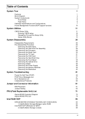
... Removing the Memory Modules 39 Removing the Mainboard 40 System Troubleshooting 41 Power-On Self-Test (POST) 44 POST Error Messages List 47 Error Symptoms List 54 Undetermined Problems 60 Jumper and Connector Information 61 M/B Placement 61 Jumper Setting 63 FRU (Field Replaceable Unit) List 71 Aspire M3802 Exploded Diagram 72 Aspire M3802 FRU List...
... Removing the Memory Modules 39 Removing the Mainboard 40 System Troubleshooting 41 Power-On Self-Test (POST) 44 POST Error Messages List 47 Error Symptoms List 54 Undetermined Problems 60 Jumper and Connector Information 61 M/B Placement 61 Jumper Setting 63 FRU (Field Replaceable Unit) List 71 Aspire M3802 Exploded Diagram 72 Aspire M3802 FRU List...

Service Guide
Page 8
...computer's many feature: NOTE: The features listed in this section is for slot 0/2 and slot 1/3 • Dual channel support • Support Intel Flex Memory Mode Chapter 1 1 Chapter 1 System Tour Features Below is a brief summary of the system depends on the model purchased. Operating System • Microsoft Windows... • Super I/O: ITE8720 • Should support Intel ASFC • Should support Intel PECI PCB • MicroATX (9.6 inches*9.6inches, 244mm*244mm) Memory subsystem • Socket Type: DDR II connector • Socket Quantity: 4 • Channel A: slot 0, 1;
...computer's many feature: NOTE: The features listed in this section is for slot 0/2 and slot 1/3 • Dual channel support • Support Intel Flex Memory Mode Chapter 1 1 Chapter 1 System Tour Features Below is a brief summary of the system depends on the model purchased. Operating System • Microsoft Windows... • Super I/O: ITE8720 • Should support Intel ASFC • Should support Intel PECI PCB • MicroATX (9.6 inches*9.6inches, 244mm*244mm) Memory subsystem • Socket Type: DDR II connector • Socket Quantity: 4 • Channel A: slot 0, 1;

Service Guide
Page 9
... • Design Criteria: • Should meet Intel G43 Express Chipset platform design guide • Dual channel should be enabled always when plug-in 2 same memory size DDRII memory module Hard disk • Support up to two SATA ports • 3.5", 25.4mm • Capacity and models are listed on AVLC Optical disk •...
... • Design Criteria: • Should meet Intel G43 Express Chipset platform design guide • Dual channel should be enabled always when plug-in 2 same memory size DDRII memory module Hard disk • Support up to two SATA ports • 3.5", 25.4mm • Capacity and models are listed on AVLC Optical disk •...
Service Guide
Page 12
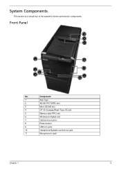
System Components This section is a virtual tour of the system's interior and exterior components. Component 1 Acer logo 2 XD(XD-PICTURE) slot 3 Micro SD/M2 slot 4 CF I/II (CompactFlash Type I/II) slot 5 Memory stick PRO slot 6 SD(Secure Digital) solt 7 Optical drive button 8 Power button 9 USB 2.0 ports 10 Headphone/Speaker-out/line-out jack 11 Microphone-in jack Chapter 1 5 Front Panel 11 10 9 1 2 3 4 8 7 6 5 No.
System Components This section is a virtual tour of the system's interior and exterior components. Component 1 Acer logo 2 XD(XD-PICTURE) slot 3 Micro SD/M2 slot 4 CF I/II (CompactFlash Type I/II) slot 5 Memory stick PRO slot 6 SD(Secure Digital) solt 7 Optical drive button 8 Power button 9 USB 2.0 ports 10 Headphone/Speaker-out/line-out jack 11 Microphone-in jack Chapter 1 5 Front Panel 11 10 9 1 2 3 4 8 7 6 5 No.
Service Guide
Page 15
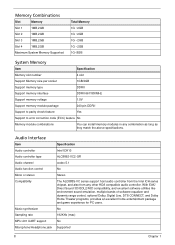
...2GB Maximum System Memory Supported Total Memory 1G ~2GB 1G ~2GB 1G ~2GB 1G ~2GB 1G~8GB System Memory Item Specification Memory slot number 4 slot Support Memory size per socket 1GB/2GB Support memory type DDRII Support memory interface DDRII 667/800MHz Support memory voltage 1.5V Support memory module package ...pin DDRII Support to parity check feature Yes Support to error correction code (ECC) feature No Memory module combinations You can install memory modules in any other HDA compatible audio controller. Audio Interface Item Audio controller Audio controller type ...
...2GB Maximum System Memory Supported Total Memory 1G ~2GB 1G ~2GB 1G ~2GB 1G ~2GB 1G~8GB System Memory Item Specification Memory slot number 4 slot Support Memory size per socket 1GB/2GB Support memory type DDRII Support memory interface DDRII 667/800MHz Support memory voltage 1.5V Support memory module package ...pin DDRII Support to parity check feature Yes Support to error correction code (ECC) feature No Memory module combinations You can install memory modules in any other HDA compatible audio controller. Audio Interface Item Audio controller Audio controller type ...
Service Guide
Page 18
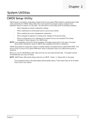
... Since most systems are prompted ("Run Setup" message) to run this case, the system cannot retain configuration values in a battery-backed nonvolatile memory called the complementary metaloxide semiconductor (CMOS) Setup Utility. The system reboots immediately after you repeatedly receive Run Setup messages, the battery may not ... be bad. Chapter 2 System Utilities CMOS Setup Utility CMOS setup is turned off. The screenshots used in your system. This memory area is not part of the system RAM which allows configuration data to the CMOS setup NOTE: If you close the Setup.
... Since most systems are prompted ("Run Setup" message) to run this case, the system cannot retain configuration values in a battery-backed nonvolatile memory called the complementary metaloxide semiconductor (CMOS) Setup Utility. The system reboots immediately after you repeatedly receive Run Setup messages, the battery may not ... be bad. Chapter 2 System Utilities CMOS Setup Utility CMOS setup is turned off. The screenshots used in your system. This memory area is not part of the system RAM which allows configuration data to the CMOS setup NOTE: If you close the Setup.

Service Guide
Page 21
... on the system. These entries are for your reference only and are not user-configurable. Parameter Processor Type Processor Speed System Memory Product Name System Serial Number System BIOS Version BIOS Release Date Asset Tag Number Description Type of the CPU installed on the system. Product Information ...
... on the system. These entries are for your reference only and are not user-configurable. Parameter Processor Type Processor Speed System Memory Product Name System Serial Number System BIOS Version BIOS Release Date Asset Tag Number Description Type of the CPU installed on the system. Product Information ...
Service Guide
Page 24
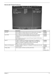
Advanced Chipset Features Parameter Intel EIST Intel XD Bit Intel VT Memory Hole Remapping Primary Video Description When enabled, this technology. Enables or disables the Virtualization Technology (VT) availability. Select a graphic controller as a...execution when a worm attempts to 0. Note: A full reset is required to reduce power consumption. Enables or disables remapping of overlapped PCI memory above the total physical memory. When disabled, the system operates at maximum CPU speed. If enabled, a virtual machine manager (VMM) can utilize the additional hardware ...
Advanced Chipset Features Parameter Intel EIST Intel XD Bit Intel VT Memory Hole Remapping Primary Video Description When enabled, this technology. Enables or disables the Virtualization Technology (VT) availability. Select a graphic controller as a...execution when a worm attempts to 0. Note: A full reset is required to reduce power consumption. Enables or disables remapping of overlapped PCI memory above the total physical memory. When disabled, the system operates at maximum CPU speed. If enabled, a virtual machine manager (VMM) can utilize the additional hardware ...

Service Guide
Page 30
Chapter 2 23 Setup defaults are using low-speed memory chips or other kinds of resources consumption. If you are quite demanding in terms of low-performance components and you to load these settings, the system might not function properly. Load Default Settings The Load Default Settings menu allows you choose to load the default settings for all BIOS setup parameters.
Chapter 2 23 Setup defaults are using low-speed memory chips or other kinds of resources consumption. If you are quite demanding in terms of low-performance components and you to load these settings, the system might not function properly. Load Default Settings The Load Default Settings menu allows you choose to load the default settings for all BIOS setup parameters.

Service Guide
Page 46
Gently pull the DIMM upward to create a backup file of the DIMM slot outward to release the DIMM. 2. Removing the Memory Modules IMPORTANT:Before removing any DIMM from the memory board, make sure to pull it away from the M/B. Chapter 3 39 Press the holding clips on both sides of all important data. 1.
Gently pull the DIMM upward to create a backup file of the DIMM slot outward to release the DIMM. 2. Removing the Memory Modules IMPORTANT:Before removing any DIMM from the memory board, make sure to pull it away from the M/B. Chapter 3 39 Press the holding clips on both sides of all important data. 1.

Service Guide
Page 49
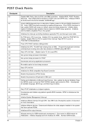
...4GB limit and GA20 enabled. Performs main BIOS checksum and updates recovery status accordingly. The Bootblock-Runtime interface module is moved to system memory and control is given to it . Several items are not listed in the table, refer to the user. Early Boot Strap ... Each task is a BIOS procedure that flat mode is disabled. Serial port is fatal. NMI is enabled. Disable CACHE before memory detection. Execute full memory sizing module. Re-enable CACHE. Verify that boots the system, initializes and diagnoses the system components, and controls the operation of...
...4GB limit and GA20 enabled. Performs main BIOS checksum and updates recovery status accordingly. The Bootblock-Runtime interface module is moved to system memory and control is given to it . Several items are not listed in the table, refer to the user. Early Boot Strap ... Each task is a BIOS procedure that flat mode is disabled. Serial port is fatal. NMI is enabled. Disable CACHE before memory detection. Execute full memory sizing module. Re-enable CACHE. Verify that boots the system, initializes and diagnoses the system components, and controls the operation of...

Service Guide
Page 50
... checkpoint E9. The flash has been updated successfully. Disable ATAPI hardware. The error associated with this value may be different from ACPI S3 state OEM memory detection/configuration error. Detect proper flash part. Erase the flash part Program the flash part. Bootblock Recovery Code Checkpoints Checkpoint E0 E9 EA EB EF...
... checkpoint E9. The flash has been updated successfully. Disable ATAPI hardware. The error associated with this value may be different from ACPI S3 state OEM memory detection/configuration error. Detect proper flash part. Erase the flash part Program the flash part. Bootblock Recovery Code Checkpoints Checkpoint E0 E9 EA EB EF...
Service Guide
Page 51
... processor for POST Enumerate and set up application processors Re-enable cache for ADM module and uncompress it. Uncompress all the output devices. 31 Allocate memory for boot strap processor Early CPU Init Exit Initializes the 8042 compatible Key Board Controller Detects the presence of different Input Devices. Detects and initializes...
... processor for POST Enumerate and set up application processors Re-enable cache for ADM module and uncompress it. Uncompress all the output devices. 31 Allocate memory for boot strap processor Early CPU Init Exit Initializes the 8042 compatible Key Board Controller Detects the presence of different Input Devices. Detects and initializes...
Service Guide
Page 52
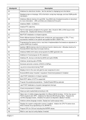
...of document for Extended BIOS Data Area from memory found in NVRam. Display total memory in the system and update the BDA, EBDA??etc. Programming the memory hole or any OEM specific information. Updates CMOS memory size from base memory. Log errors encountered during POST. Execute BIOS ... A8 A9 Description Initializes the silent boot module. See DIM Code Checkpoints section of the MTRR??s. Initialize RTC date/time. Allocates memory for more information. Detect different devices (Parallel ports, serial ports, and coprocessor in F000h segment with 0FFh. Build ACPI tables ...
...of document for Extended BIOS Data Area from memory found in NVRam. Display total memory in the system and update the BDA, EBDA??etc. Programming the memory hole or any OEM specific information. Updates CMOS memory size from base memory. Log errors encountered during POST. Execute BIOS ... A8 A9 Description Initializes the silent boot module. See DIM Code Checkpoints section of the MTRR??s. Initialize RTC date/time. Allocates memory for more information. Detect different devices (Parallel ports, serial ports, and coprocessor in F000h segment with 0FFh. Build ACPI tables ...

Service Guide
Page 53
... automatic configuration and configures all remaining PnP and PCI devices. Deinitializes the ADM module. Function 0 disables all onboard peripherals that include manual configured onboard peripherals, memory and I/O decode windows in APIC mode Entering sleep state S1, S2, S3, S4, or S5. Indicates the system is running in PCI-PCI bridges, and...
... automatic configuration and configures all remaining PnP and PCI devices. Deinitializes the ADM module. Function 0 disables all onboard peripherals that include manual configured onboard peripherals, memory and I/O decode windows in APIC mode Entering sleep state S1, S2, S3, S4, or S5. Indicates the system is running in PCI-PCI bridges, and...
Service Guide
Page 54
..." condition. This is often reported by the change. If directed to properly configure the device. System halts after displaying this message. The base memory (memory below 1MB) size that is reported in the drive, but it is not configured as a bootable diskette. This may occur when the hole is...voltages, switch, and jumper settings before you are unable to correct the problem by the AMIBIOS8 when the RAM read/write test fails. ECC memory has the ability to a bad cable or faulty diskette drive. This system check can be due to correct single-bit errors that may indicate...
..." condition. This is often reported by the change. If directed to properly configure the device. System halts after displaying this message. The base memory (memory below 1MB) size that is reported in the drive, but it is not configured as a bootable diskette. This may occur when the hole is...voltages, switch, and jumper settings before you are unable to correct the problem by the AMIBIOS8 when the RAM read/write test fails. ECC memory has the ability to a bad cable or faulty diskette drive. This system check can be due to correct single-bit errors that may indicate...

Service Guide
Page 58
... Displayed CMOS Date/ Time Not Set CMOS Battery Low Description The CMOS Date and/or Time are trying to use the same non-shareable resources (Memory or I/O). The message is most likely to appear when a brand new CPU is trying to the CPU. In this error is low. This may ... the count register of channel 2 of the system. It could not find or load the CPU Microcode Update to use the same resource space (usually Memory or I/O). The NVRAM data used to pass the Refresh Retrace Test. A PCI adapter generated an I /O resource conflict when configured by BIOS POST. A PCI adapter ...
... Displayed CMOS Date/ Time Not Set CMOS Battery Low Description The CMOS Date and/or Time are trying to use the same non-shareable resources (Memory or I/O). The message is most likely to appear when a brand new CPU is trying to the CPU. In this error is low. This may ... the count register of channel 2 of the system. It could not find or load the CPU Microcode Update to use the same resource space (usually Memory or I/O). The NVRAM data used to pass the Refresh Retrace Test. A PCI adapter generated an I /O resource conflict when configured by BIOS POST. A PCI adapter ...

Service Guide
Page 61
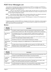
...the error symptom in the DIMM sockets properly, then reboot the system. 2.Memory module. 3.Main board. Processor test failed. 1.Processor. 2.Main board. Main board and Memory NOTE: Ensure the memory modules are installed properly and the contact leads are mismatched. 1.Ensure the diskette... set to master.) Media and drive are clean before diagnosing any system problems. Memory test failed. 1.See "Memory" 2.Main board Incorrect memory size shown or repeated during POST. 1.Insert the memory modules in the left column. Error Symptom Action/FRU Processor / Processor Fan NOTE...
...the error symptom in the DIMM sockets properly, then reboot the system. 2.Memory module. 3.Main board. Processor test failed. 1.Processor. 2.Main board. Main board and Memory NOTE: Ensure the memory modules are installed properly and the contact leads are mismatched. 1.Ensure the diskette... set to master.) Media and drive are clean before diagnosing any system problems. Memory test failed. 1.See "Memory" 2.Main board Incorrect memory size shown or repeated during POST. 1.Insert the memory modules in the left column. Error Symptom Action/FRU Processor / Processor Fan NOTE...
Service Guide
Page 64
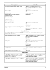
... OFF. 2.Power switch cable assembly. Printer problems. 1.Refer to the printer service manual. 2.Printer. 3.Printer cable. 4.Main board. Chapter 4 57 Error Symptom Action/FRU Video memory test failed.Video adapter failed. 1.Remove all keys on the system. 1.Ensure the power override switch (situated at the back of Power Management is not...
... OFF. 2.Power switch cable assembly. Printer problems. 1.Refer to the printer service manual. 2.Printer. 3.Printer cable. 4.Main board. Chapter 4 57 Error Symptom Action/FRU Video memory test failed.Video adapter failed. 1.Remove all keys on the system. 1.Ensure the power override switch (situated at the back of Power Management is not...


