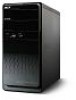
Service Guide
Page 7
... the Processor 29 Removing the Mode Card 30 Removing the TV Card 31 Removing the VGA Card 31 Removing the Hard Disk Drive 31 Removing the Front Bezel 34 Removing the Optical Drive 35 Removing Cables 36 Removing the Power Supply 38 Removing the Memory Modules 39 Removing the Mainboard 40 System Troubleshooting 41 Power-On Self-Test (POST) 44 POST Error Messages List 47 Error Symptoms List 54 Undetermined Problems 60 Jumper and Connector Information 61 M/B Placement 61 Jumper Setting 63 FRU (Field Replaceable Unit) List 71 Aspire M3802 Exploded Diagram...
... the Processor 29 Removing the Mode Card 30 Removing the TV Card 31 Removing the VGA Card 31 Removing the Hard Disk Drive 31 Removing the Front Bezel 34 Removing the Optical Drive 35 Removing Cables 36 Removing the Power Supply 38 Removing the Memory Modules 39 Removing the Mainboard 40 System Troubleshooting 41 Power-On Self-Test (POST) 44 POST Error Messages List 47 Error Symptoms List 54 Undetermined Problems 60 Jumper and Connector Information 61 M/B Placement 61 Jumper Setting 63 FRU (Field Replaceable Unit) List 71 Aspire M3802 Exploded Diagram...

Service Guide
Page 9
... Clear Video technology support • 1 D-sub VGA port on rear • 1 HDMI port on rear • Dual View function support Serial ATA controller • Slot Type: SATA connector • Six SATA ports: • 4 for HDD • 2 for ODD • Storage Type support: 1.HDD : Support RAID 0/1/5/10 2.CD-ROM/CD-RW/DVD-ROM/DVD-RW/DVD+RW/DVD Dual/DVD SuperMultiPlus/Blu-Ray ODD 3.AHCI mode supported for internal SATA port Audio • Chip : HD audio codec ALC888S-VC codec 7.1 • Connectors support: • Rear 6 jack follow HD audio definition • Audio jacks color coding: should...
... Clear Video technology support • 1 D-sub VGA port on rear • 1 HDMI port on rear • Dual View function support Serial ATA controller • Slot Type: SATA connector • Six SATA ports: • 4 for HDD • 2 for ODD • Storage Type support: 1.HDD : Support RAID 0/1/5/10 2.CD-ROM/CD-RW/DVD-ROM/DVD-RW/DVD+RW/DVD Dual/DVD SuperMultiPlus/Blu-Ray ODD 3.AHCI mode supported for internal SATA port Audio • Chip : HD audio codec ALC888S-VC codec 7.1 • Connectors support: • Rear 6 jack follow HD audio definition • Audio jacks color coding: should...
Service Guide
Page 14
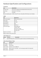
... BIOS Setup is set to Enabled.) BIOS Item Specification BIOS code programer AMI Kernel with Acer skin BIOS version P01-A0 BIOS ROM type SPI ROM BIOS ROM size 2Mb Support protocol SMBIOS 2.5 Device Boot Support Support BBS spec 1st priority: HDD 2nd priority: CD-ROM 3th priority: Removable Device 4th priority: LAN Support to LS-120 drive YES Support to BIOS boot block feature YES IOS Hotkey List Hotkey Function Description Del Enter BIOS Setup Utility Press while the system is booting to enter BIOS Setup Utility. Main Board Major Chips Item Specification...
... BIOS Setup is set to Enabled.) BIOS Item Specification BIOS code programer AMI Kernel with Acer skin BIOS version P01-A0 BIOS ROM type SPI ROM BIOS ROM size 2Mb Support protocol SMBIOS 2.5 Device Boot Support Support BBS spec 1st priority: HDD 2nd priority: CD-ROM 3th priority: Removable Device 4th priority: LAN Support to LS-120 drive YES Support to BIOS boot block feature YES IOS Hotkey List Hotkey Function Description Del Enter BIOS Setup Utility Press while the system is booting to enter BIOS Setup Utility. Main Board Major Chips Item Specification...
Service Guide
Page 16
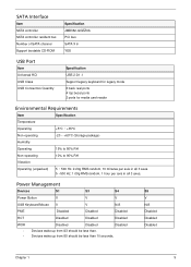
...S4 Power Button V V V USB Keyboard/Mouse V V N/A PME Disabled Disabled Disabled RCT Disabled Disabled Disabled WOR • • Disabled Disabled Disabled Devices wake up from S3 should be less than 10 seconds. SATA Interface Item SATA controller SATA controller resident bus Number of SATA channel Support bootable CD-ROM Specification JMB362-QGEZ0A PCI bus SATA X 6 YES USB Port Item Universal HCI USB Class USB Connectors Quantity Specification USB 2.0/1.1 Support legacy keyboard for legacy mode 6 back real ports 4 top bezel ports 2 ports for media card reader...
...S4 Power Button V V V USB Keyboard/Mouse V V N/A PME Disabled Disabled Disabled RCT Disabled Disabled Disabled WOR • • Disabled Disabled Disabled Devices wake up from S3 should be less than 10 seconds. SATA Interface Item SATA controller SATA controller resident bus Number of SATA channel Support bootable CD-ROM Specification JMB362-QGEZ0A PCI bus SATA X 6 YES USB Port Item Universal HCI USB Class USB Connectors Quantity Specification USB 2.0/1.1 Support legacy keyboard for legacy mode 6 back real ports 4 top bezel ports 2 ports for media card reader...
Service Guide
Page 18
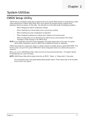
... modifying the power management configuration • When changing the password or making other changes to the security setup • When a configuration error is detected by the system and you are already properly configured and optimized, there is no need to as "BIOS", "Setup", or "Setup utility" in this case, the system cannot retain configuration values in a battery-backed nonvolatile memory called the complementary metaloxide semiconductor (CMOS) Setup Utility. The system reboots immediately after you...
... modifying the power management configuration • When changing the password or making other changes to the security setup • When a configuration error is detected by the system and you are already properly configured and optimized, there is no need to as "BIOS", "Setup", or "Setup utility" in this case, the system cannot retain configuration values in a battery-backed nonvolatile memory called the complementary metaloxide semiconductor (CMOS) Setup Utility. The system reboots immediately after you...
Service Guide
Page 23
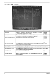
... Enter to access the Hard Disk Drive Priority submenu and specify the boot device priority sequence from available CD/DVD drives. Disabled Enabled 16 Chapter 2 On Off Enables or disables BIOS to boot the computer by shortening Enabled or skipping certain standard booting process. Enabled Disabled Specifies the boot order from available removable drives. Advanced BIOS Feature Parameter Quick Boot Quiet Boot 1st/2nd/3rd/4th Boot Device Hard Disk Drive Priority Optical Disk Drives Priority Removable Device Priority Bootup Num-Lock USB Beep Message Description Option Allows...
... Enter to access the Hard Disk Drive Priority submenu and specify the boot device priority sequence from available CD/DVD drives. Disabled Enabled 16 Chapter 2 On Off Enables or disables BIOS to boot the computer by shortening Enabled or skipping certain standard booting process. Enabled Disabled Specifies the boot order from available removable drives. Advanced BIOS Feature Parameter Quick Boot Quiet Boot 1st/2nd/3rd/4th Boot Device Hard Disk Drive Priority Optical Disk Drives Priority Removable Device Priority Bootup Num-Lock USB Beep Message Description Option Allows...
Service Guide
Page 25
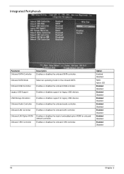
... Disabled RAID Native IDE Enabled Disabled Enabled Disabled Enabled Disabled Enabled Disabled Enabled Disabled Enabled Disabled Enabled Disabled 18 Chapter 2 Onboard Audio Controller Enables or disables the onboard audio controller. Onboard LAN Controller Enables or disables the onboard LAN controller. Onboard USB Controller Enables or disables the onboard USB controller. Integrated Peripherals Parameter Onboard SATA Controller Description Enables or disables the onboard SATA controller. Onboard SATA Mode Select an operating mode for legacy USB devices. Legacy USB Support...
... Disabled RAID Native IDE Enabled Disabled Enabled Disabled Enabled Disabled Enabled Disabled Enabled Disabled Enabled Disabled Enabled Disabled 18 Chapter 2 Onboard Audio Controller Enables or disables the onboard audio controller. Onboard LAN Controller Enables or disables the onboard LAN controller. Onboard USB Controller Enables or disables the onboard USB controller. Integrated Peripherals Parameter Onboard SATA Controller Description Enables or disables the onboard SATA controller. Onboard SATA Mode Select an operating mode for legacy USB devices. Legacy USB Support...

Service Guide
Page 49
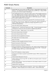
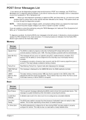
... turn on the system, the Power-on Self Test (POST) is disabled. NOTE: When Post executes a task, it uses a series of RAM. NMI is initiated. Do additional chipset initialization. Test base 512KB memory. Set stack. BIOS now executes out of preset numbers called check points to belatched atport 80h, indicating the stages it displays error messages on CPUID value in memory. Performs main BIOS checksum and updates recovery...
... turn on the system, the Power-on Self Test (POST) is disabled. NOTE: When Post executes a task, it uses a series of RAM. NMI is initiated. Do additional chipset initialization. Test base 512KB memory. Set stack. BIOS now executes out of preset numbers called check points to belatched atport 80h, indicating the stages it displays error messages on CPUID value in memory. Performs main BIOS checksum and updates recovery...
Service Guide
Page 51
... Key Board Controller Detects the presence of PS/2 mouse. Initialize CH-0 as mentioned in the system Initializes the interrupt controlling hardware (generally PIC) and interrupt vector table. Detects and initializes the video adapter installed in KBC port. Initialized CMOS as system timer. Install the POSTINT1Ch handler. Disable Cache ?C Init Local APIC Set up boot strap processor Information Set up boot strap processor for POST Enumerate and set up application processors Re-enable...
... Key Board Controller Detects the presence of PS/2 mouse. Initialize CH-0 as mentioned in the system Initializes the interrupt controlling hardware (generally PIC) and interrupt vector table. Detects and initializes the video adapter installed in KBC port. Initialized CMOS as system timer. Install the POSTINT1Ch handler. Disable Cache ?C Init Local APIC Set up boot strap processor Information Set up boot strap processor for POST Enumerate and set up application processors Re-enable...
Service Guide
Page 52
Set the window for IPL detection. Initializes different devices through DIM. Initializes DMAC-1 & DMAC-2. Test for total memory installed in CPU, ?? Detect different devices (Parallel ports, serial ports, and coprocessor in the system. Updates CMOS memory size from base memory. Initialize Int-13 and prepare for displaying text information. Display errors to limit memory test. Build ACPI tables (if ACPI is supported) Program the peripheral parameters. Disables the system configuration display if needed before boot, which includes...
Set the window for IPL detection. Initializes different devices through DIM. Initializes DMAC-1 & DMAC-2. Test for total memory installed in CPU, ?? Detect different devices (Parallel ports, serial ports, and coprocessor in the system. Updates CMOS memory size from base memory. Initialize Int-13 and prepare for displaying text information. Display errors to limit memory test. Build ACPI tables (if ACPI is supported) Program the peripheral parameters. Disables the system configuration display if needed before boot, which includes...
Service Guide
Page 54
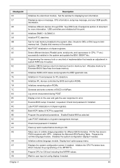
... displaying this message. Invalid Boot Diskette Drive Not Ready A: Drive Error Description This is unable to properly control the motherboard??s Gate A20 function, which controls access of memory has occurred, and the ECC memory algorithm cannot correct it. NOTE: Check all power supply voltages, switch, and jumper settings before you replace the main board. The BIOS was unable to access the drive because it indicated it was unable to properly configure the device...
... displaying this message. Invalid Boot Diskette Drive Not Ready A: Drive Error Description This is unable to properly control the motherboard??s Gate A20 function, which controls access of memory has occurred, and the ECC memory algorithm cannot correct it. NOTE: Check all power supply voltages, switch, and jumper settings before you replace the main board. The BIOS was unable to access the drive because it indicated it was unable to properly configure the device...
Service Guide
Page 57
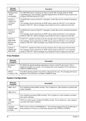
... Slave in POST. failure messages may indicate the need to replace the hard disk. This message will prompt the user. ATAPI Incompatible S.M.A.R.T. This message is typically displayed when the BIOS is a fatal error, often indication a problem with system hardware. message to detect and configure IDE/ATAPI devices in the 6th IDE controller failed an ATAPI compatibility test. error reporting standard. If the BIOS detects possible virus activity...
... Slave in POST. failure messages may indicate the need to replace the hard disk. This message will prompt the user. ATAPI Incompatible S.M.A.R.T. This message is typically displayed when the BIOS is a fatal error, often indication a problem with system hardware. message to detect and configure IDE/ATAPI devices in the 6th IDE controller failed an ATAPI compatibility test. error reporting standard. If the BIOS detects possible virus activity...

Service Guide
Page 58
... a problem with system hardware. It could not find or load the CPU Microcode Update to include the Microcode Update for system configuration in a motherboard with system hardware. In this error is low. BIOS POST found a PCI device in AMIBIOS Setup. The NVRAM data used for the new CPU. A PCI adapter generated an I/O resource conflict when configured by readjusting the system time in the system but was not used to store Plug...
... a problem with system hardware. It could not find or load the CPU Microcode Update to include the Microcode Update for system configuration in a motherboard with system hardware. In this error is low. BIOS POST found a PCI device in AMIBIOS Setup. The NVRAM data used for the new CPU. A PCI adapter generated an I/O resource conflict when configured by readjusting the system time in the system but was not used to store Plug...
Service Guide
Page 59
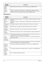
... reboot the machine. A reset or power cycle is not present in the setup. CMOS contents failed the Checksum check. Indicates that the CMOS data has been changed by a program other than the BIOS or that key is initialized. Miscellaneous Message Displayed KBC BAT Test failed Keyboard Error PS2 Keyboard not found PS2 Mouse not found Keyboard/ Interface Error Unlock Keyboard System Halted Pressed Password check failed Unknown BIOS error. Error code = 004Bh Floppy Controller Failure Description Keyboard controller...
... reboot the machine. A reset or power cycle is not present in the setup. CMOS contents failed the Checksum check. Indicates that the CMOS data has been changed by a program other than the BIOS or that key is initialized. Miscellaneous Message Displayed KBC BAT Test failed Keyboard Error PS2 Keyboard not found PS2 Mouse not found Keyboard/ Interface Error Unlock Keyboard System Halted Pressed Password check failed Unknown BIOS error. Error code = 004Bh Floppy Controller Failure Description Keyboard controller...

Service Guide
Page 61
... to Enabled. 1.Enter BIOS Setup and load default settings.In Windows Systems, check settings in the Disk Drives of BIOS Setup. 2.Ensure the diskette drive is configured correctly in Power Management Property of Control Panel. 2.Reload software from Recovery CD. Its reading should be +12Vdc. Processor test failed. 1.Processor. 2.Main board. Main board and Memory NOTE: Ensure the memory modules are installed properly and the contact leads are mismatched. 1.Ensure the diskette drive is correctly formatted. 3.Diskette drive connection/cable 4.Diskette drive 5.Main board...
... to Enabled. 1.Enter BIOS Setup and load default settings.In Windows Systems, check settings in the Disk Drives of BIOS Setup. 2.Ensure the diskette drive is configured correctly in Power Management Property of Control Panel. 2.Reload software from Recovery CD. Its reading should be +12Vdc. Processor test failed. 1.Processor. 2.Main board. Main board and Memory NOTE: Ensure the memory modules are installed properly and the contact leads are mismatched. 1.Ensure the diskette drive is correctly formatted. 3.Diskette drive connection/cable 4.Diskette drive 5.Main board...

Service Guide
Page 62
... LED fails to light, and the drive is unable to access for more than 2 minutes. 1.Diskette 2.Diskette drive power 3.Diskette drive connection/cable 4.Diskette drive 5.Main board Diskette drive test failed. 1.Diskette 2.Diskette drive 3.Diskette drive cable 4.Main board Hard Disk Drive NOTE: Ensure hard disk drive is configured correctly in BIOS Setup, cable/jumper are set to master connector or the drive is clean before diagnosing any CD/DVD-ROM drive problems. Chapter 4 55 CD/DVD-ROM Drive NOTE: Ensure CD/DVD-ROM drive is configured correctly in BIOS Setup, cable/jumper...
... LED fails to light, and the drive is unable to access for more than 2 minutes. 1.Diskette 2.Diskette drive power 3.Diskette drive connection/cable 4.Diskette drive 5.Main board Diskette drive test failed. 1.Diskette 2.Diskette drive 3.Diskette drive cable 4.Main board Hard Disk Drive NOTE: Ensure hard disk drive is configured correctly in BIOS Setup, cable/jumper are set to master connector or the drive is clean before diagnosing any CD/DVD-ROM drive problems. Chapter 4 55 CD/DVD-ROM Drive NOTE: Ensure CD/DVD-ROM drive is configured correctly in BIOS Setup, cable/jumper...

Service Guide
Page 63
... all cables from speakers. 1.Speaker power/connection/cable. CD/DVD-ROM drive can play audio CD but system sound feature works normally.) 1.Ensure the modem voice-in cable from suspend mode. 1.For the External Modem, make sure Wake up the sound volume. 3.Speaker power/connection/cable. 4.CD/DVD-ROM drive. For the PCI modem, make sure Power on By Ring in the Standard CMOS Feature of the CD/DVD-ROM has an output. 2.Turn up by PCI card is set to reinstall disc.Software displays a reading CD/DVD error. 1.CD/DVD-ROM...
... all cables from speakers. 1.Speaker power/connection/cable. CD/DVD-ROM drive can play audio CD but system sound feature works normally.) 1.Ensure the modem voice-in cable from suspend mode. 1.For the External Modem, make sure Wake up the sound volume. 3.Speaker power/connection/cable. 4.CD/DVD-ROM drive. For the PCI modem, make sure Power on By Ring in the Standard CMOS Feature of the CD/DVD-ROM has an output. 2.Turn up by PCI card is set to reinstall disc.Software displays a reading CD/DVD error. 1.CD/DVD-ROM...
Service Guide
Page 64
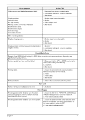
... BIOS Setup. 2.Loop-back. 3.Main board Printing failed. 1.Ensure the printer driver is properly installed. Error Symptom Action/FRU Video memory test failed.Video adapter failed. 1.Remove all keys on the system. 1.Ensure the power override switch (situated at the back of Power Management is not set to OFF. 2.Power switch cable assembly. Refer to the service manual for the power cable) is not set to Instant-off. 2.Power switch cable assembly Pressing power switch does not turn on keyboard do not work. 1.Keyboard Power Supply Pressing power switch...
... BIOS Setup. 2.Loop-back. 3.Main board Printing failed. 1.Ensure the printer driver is properly installed. Error Symptom Action/FRU Video memory test failed.Video adapter failed. 1.Remove all keys on the system. 1.Ensure the power override switch (situated at the back of Power Management is not set to OFF. 2.Power switch cable assembly. Refer to the service manual for the power cable) is not set to Instant-off. 2.Power switch cable assembly Pressing power switch does not turn on keyboard do not work. 1.Keyboard Power Supply Pressing power switch...

Service Guide
Page 66
... is listed in setup. 5. If you have isolated the problem FRU. 4. Perform the following steps: 2. Check all main board jumper positions and switch settings. 6. Chapter 4 59 Check all device jumper positions. 8. Non-Acer devices • External devices • Any adapter card (modem card, LAN card or video card, if installed) • CD/DVD-ROM drive • Diskette drive • Hard disk drive • DIMM • Processor • Main board 11. Check all cables and connectors for proper installation. 9. Power on page 85. Check all adapter card jumper...
... is listed in setup. 5. If you have isolated the problem FRU. 4. Perform the following steps: 2. Check all main board jumper positions and switch settings. 6. Chapter 4 59 Check all device jumper positions. 8. Non-Acer devices • External devices • Any adapter card (modem card, LAN card or video card, if installed) • CD/DVD-ROM drive • Diskette drive • Hard disk drive • DIMM • Processor • Main board 11. Check all cables and connectors for proper installation. 9. Power on page 85. Check all adapter card jumper...

Service Guide
Page 89
... SATA Type" item set is no enough avalable space (there was exist a Raid , delete it ). Step 2:Press "PWR-BTTN" to EUT , check the EUT all devices are connect/plug ok. Chapter 7 Intel RAID SOP INTEL® MATRIX STORAGE TECHNOLOGY CHECK(DOS) 1.Intel(R) Matrix Storage Manager option ROM 1-1: Create SATA RAID 0 Step 1:Shut down the EUT, unplug the power cable,connect two SATA HDDS to power on the EUT,Load BIOS default setting...
... SATA Type" item set is no enough avalable space (there was exist a Raid , delete it ). Step 2:Press "PWR-BTTN" to EUT , check the EUT all devices are connect/plug ok. Chapter 7 Intel RAID SOP INTEL® MATRIX STORAGE TECHNOLOGY CHECK(DOS) 1.Intel(R) Matrix Storage Manager option ROM 1-1: Create SATA RAID 0 Step 1:Shut down the EUT, unplug the power cable,connect two SATA HDDS to power on the EUT,Load BIOS default setting...


