Acer Aspire M3420 Desktop Service Guide
Page 7
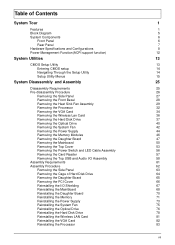
...-disassembly Procedure 26 Removing the Side Panel 27 Removing the Front Bezel 28 Removing the Heat Sink Fan Assembly 29 Removing the Processor 32 Removing the VGA Card 34 Removing the Wireless Lan Card 36 Removing the Hard Disk Drive 37 Removing the Optical Drive 40 Removing the System Fan 42 Removing the Power Supply 44 Removing the Memory Modules 46 Removing the Daughter Board 47 Removing the Mainboard 50 Removing the Top Cover 53 Removing the Power Switch and LED Cable Assembly 56 Removing the Card Reader 57 Removing the Top USB and Audio...
...-disassembly Procedure 26 Removing the Side Panel 27 Removing the Front Bezel 28 Removing the Heat Sink Fan Assembly 29 Removing the Processor 32 Removing the VGA Card 34 Removing the Wireless Lan Card 36 Removing the Hard Disk Drive 37 Removing the Optical Drive 40 Removing the System Fan 42 Removing the Power Supply 44 Removing the Memory Modules 46 Removing the Daughter Board 47 Removing the Mainboard 50 Removing the Top Cover 53 Removing the Power Switch and LED Cable Assembly 56 Removing the Card Reader 57 Removing the Top USB and Audio...
Acer Aspire M3420 Desktop Service Guide
Page 8
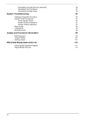
Reinstalling the Heat Sink Fan Assembly 85 Reinstalling the Front Bezel 87 Reinstalling the Side Panel 89 System Troubleshooting 90 Hardware Diagnostic Procedure 90 System Check Procedures 91 Power System Check 91 System External Inspection 91 System Internal Inspection 91 Beep Codes 92 Checkpoints 93 BIOS Recovery 96 Jumper and Connector Information 99 M/B Placement 99 Jumper Setting 101 Setting Jumper 101 FRU (Field Replaceable Unit) List 110 Aspire M3420 Exploded Diagram 111 Aspire M3420 FRU List 113 viii
Reinstalling the Heat Sink Fan Assembly 85 Reinstalling the Front Bezel 87 Reinstalling the Side Panel 89 System Troubleshooting 90 Hardware Diagnostic Procedure 90 System Check Procedures 91 Power System Check 91 System External Inspection 91 System Internal Inspection 91 Beep Codes 92 Checkpoints 93 BIOS Recovery 96 Jumper and Connector Information 99 M/B Placement 99 Jumper Setting 101 Setting Jumper 101 FRU (Field Replaceable Unit) List 110 Aspire M3420 Exploded Diagram 111 Aspire M3420 FRU List 113 viii
Acer Aspire M3420 Desktop Service Guide
Page 10
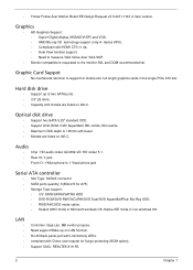
...; 3.5" SATA/SATAII/SATAIII HDD. • DVD-ROM/DVD-RW/DVD+RW/DVD Dual/DVD SuperMultiPlus/ Blu-Ray ODD. • RAID/AHCI/IDE mode option. • Default AHCI mode in non-windows OS. Support IOAC: REALTEK 8111FA. 2 Chapter 1 Hard disk drive • Support up on AVLC. Need support Wake up to the monitor AVL and DQM recommended list. Graphic Card Suppot • No mechanical retriction to 185mm with China rural request for Surge protecting (BOM option). RJ-45 Back panel port...
...; 3.5" SATA/SATAII/SATAIII HDD. • DVD-ROM/DVD-RW/DVD+RW/DVD Dual/DVD SuperMultiPlus/ Blu-Ray ODD. • RAID/AHCI/IDE mode option. • Default AHCI mode in non-windows OS. Support IOAC: REALTEK 8111FA. 2 Chapter 1 Hard disk drive • Support up on AVLC. Need support Wake up to the monitor AVL and DQM recommended list. Graphic Card Suppot • No mechanical retriction to 185mm with China rural request for Surge protecting (BOM option). RJ-45 Back panel port...
Acer Aspire M3420 Desktop Service Guide
Page 11
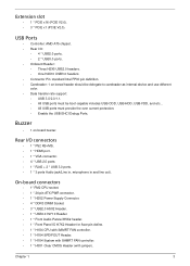
...*10 Header. • 1 * Front Audio Pannel H5X2 header. • 1 * Front Panel IO H7X2 Header for Acer pin define. • 1 * H1X4 CPU with SAMRT FAN controller. • 1 * H1X4 SPDIFOUT Header. • 1 * H1X4 System with SAMRT FAN controller. • 1 * H3X1 Clear CMOS Header (with jumper). USB Ports • Controller: AMD A75 chipset. • Rear I /O connectors • 1 * PS2 KB+MS. • 1 * HDMI port. • 1 * VGA connector. • 4 * USB 2.0 ports. • 1 * RJ45 + 2 * USB 3.0 ports. • 1 * 3 ports Audio jack(Line in, microphone...
...*10 Header. • 1 * Front Audio Pannel H5X2 header. • 1 * Front Panel IO H7X2 Header for Acer pin define. • 1 * H1X4 CPU with SAMRT FAN controller. • 1 * H1X4 SPDIFOUT Header. • 1 * H1X4 System with SAMRT FAN controller. • 1 * H3X1 Clear CMOS Header (with jumper). USB Ports • Controller: AMD A75 chipset. • Rear I /O connectors • 1 * PS2 KB+MS. • 1 * HDMI port. • 1 * VGA connector. • 4 * USB 2.0 ports. • 1 * RJ45 + 2 * USB 3.0 ports. • 1 * 3 ports Audio jack(Line in, microphone...
Acer Aspire M3420 Desktop Service Guide
Page 12
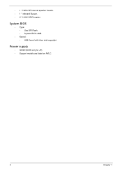
• 1 * H2X4 HD internal speaker header. • 1 * onboard Buzzer. • 2 * H1X2 GPIO header. Power supply • 300W/(500W only for JP). • Support models are listed on AVLC. 4 Chapter 1 System BIOS • Type: • Use SPI Flash. • System BIOS 4MB. • Kernel: • AMI Kernel with Acer skin/copyright.
• 1 * H2X4 HD internal speaker header. • 1 * onboard Buzzer. • 2 * H1X2 GPIO header. Power supply • 300W/(500W only for JP). • Support models are listed on AVLC. 4 Chapter 1 System BIOS • Type: • Use SPI Flash. • System BIOS 4MB. • Kernel: • AMI Kernel with Acer skin/copyright.
Acer Aspire M3420 Desktop Service Guide
Page 14
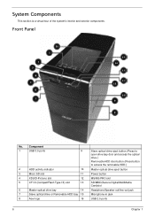
Front Panel No. Component 1 USB 3.0 ports 9 2 HDD activity indicator 10 3 Micro SD slot 11 4 XD(XD-Picture) slot 12 5 CF I/II (CompactFlash Type I/II) slot 13 6 Master optical drive bay 14 7 Slave optical drive or Removable HDD bay 15 8 Acer logo 16 Slave optical drive eject button.(Press to open drive bay door and access the optical drive.) Removable HDD door button.(Press button to access the removable HDD.) Master optical drive eject button Power button MS/MS PRO slot SD/MMC(Secure Digital/MultiMedia Card)slot Headphone/Speaker-out...
Front Panel No. Component 1 USB 3.0 ports 9 2 HDD activity indicator 10 3 Micro SD slot 11 4 XD(XD-Picture) slot 12 5 CF I/II (CompactFlash Type I/II) slot 13 6 Master optical drive bay 14 7 Slave optical drive or Removable HDD bay 15 8 Acer logo 16 Slave optical drive eject button.(Press to open drive bay door and access the optical drive.) Removable HDD door button.(Press button to access the removable HDD.) Master optical drive eject button Power button MS/MS PRO slot SD/MMC(Secure Digital/MultiMedia Card)slot Headphone/Speaker-out...
Acer Aspire M3420 Desktop Service Guide
Page 16
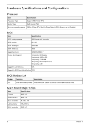
... AMD A75 Audio controller ALC662-VD LAN controller RTL8111FA SATA controller AMD A75 8 Chapter 1 Hardware Specifications and Configurations Processor Item Specification Processor Type Support AMD Trinity APU Socket Type AMD Socket-FM2 Minimum operating speed 0 MHz (If Stop CPU Clock in Sleep State in BIOS Setup is set to Enabled.) BIOS Item Specification BIOS code programer AMI Kernel with Acer skin BIOS version P01-A0 BIOS ROM type SPI Flash BIOS ROM size 4MB Support protocol SMBIOS(DMI)2.7 Device Boot Support 1st priority: EFI Deivce 2nd priority: SATA HDD 3rd...
... AMD A75 Audio controller ALC662-VD LAN controller RTL8111FA SATA controller AMD A75 8 Chapter 1 Hardware Specifications and Configurations Processor Item Specification Processor Type Support AMD Trinity APU Socket Type AMD Socket-FM2 Minimum operating speed 0 MHz (If Stop CPU Clock in Sleep State in BIOS Setup is set to Enabled.) BIOS Item Specification BIOS code programer AMI Kernel with Acer skin BIOS version P01-A0 BIOS ROM type SPI Flash BIOS ROM size 4MB Support protocol SMBIOS(DMI)2.7 Device Boot Support 1st priority: EFI Deivce 2nd priority: SATA HDD 3rd...
Acer Aspire M3420 Desktop Service Guide
Page 17
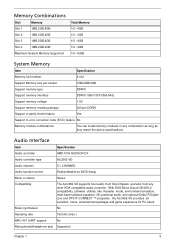
... System Memory Item Specification Memory slot number 4 slot Support Memory size per socket 1GB/2GB/4GB Support memory type DDRIII Support memory interface DDRIII 1066/1333/1866 MHz Support memory voltage 1.5V Support memory module package 240-pin DDRIII Support to parity check feature Yes Support to error correction code (ECC) feature No Memory module combinations You can install memory modules in any other HDA compatible audio controller. With EAX/Direct Sound 3D/I3DL2 compatibility, software utilities like Karaoke mode, environment...
... System Memory Item Specification Memory slot number 4 slot Support Memory size per socket 1GB/2GB/4GB Support memory type DDRIII Support memory interface DDRIII 1066/1333/1866 MHz Support memory voltage 1.5V Support memory module package 240-pin DDRIII Support to parity check feature Yes Support to error correction code (ECC) feature No Memory module combinations You can install memory modules in any other HDA compatible audio controller. With EAX/Direct Sound 3D/I3DL2 compatibility, software utilities like Karaoke mode, environment...
Acer Aspire M3420 Desktop Service Guide
Page 19
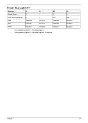
S5 V N/A Disabled Disabled Disabled Chapter 1 11 Power Management Devices S1 S3 S4 Power Button V V V USB Keyboard/Mouse V V N/A PME Disabled Disabled Disabled RCT Disabled Disabled Disabled WOR Disabled Disabled Disabled • Devices wake up from S3 should be less than. • Devices wake up from S5 should be less than 10 seconds.
S5 V N/A Disabled Disabled Disabled Chapter 1 11 Power Management Devices S1 S3 S4 Power Button V V V USB Keyboard/Mouse V V N/A PME Disabled Disabled Disabled RCT Disabled Disabled Disabled WOR Disabled Disabled Disabled • Devices wake up from S3 should be less than. • Devices wake up from S5 should be less than 10 seconds.
Acer Aspire M3420 Desktop Service Guide
Page 20
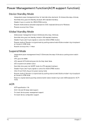
... in,keyboard an mouse for APM mode. • Resume recovery time :7-10sec Suspend Mode • Independent power management timer(2-120minutes,time step=10minute)or pushing extern switch button. • CPU goes into SMM • CPU asserts STPCLK# and goes into the Stop Grant State. • LED on panel turns amber colour. • Hard disk drive goes into SLEEP mode (for ATA standard interface). • Disable H-sync and V-sync signals to control the...
... in,keyboard an mouse for APM mode. • Resume recovery time :7-10sec Suspend Mode • Independent power management timer(2-120minutes,time step=10minute)or pushing extern switch button. • CPU goes into SMM • CPU asserts STPCLK# and goes into the Stop Grant State. • LED on panel turns amber colour. • Hard disk drive goes into SLEEP mode (for ATA standard interface). • Disable H-sync and V-sync signals to control the...
Acer Aspire M3420 Desktop Service Guide
Page 21
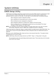
... CMOS Setup Utility, make changes to be bad. These values may be retained when power is turned off. Chapter 2 System Utilities CMOS Setup Utility CMOS setup is a hardware configuration program built into the system ROM, called CMOS RAM. The screenshots used in CMOS. Chapter 2 13 You will be the same those found in this utility. The system reboots immediately after you have saved all open files. Ask a qualified technician for assistance. NOTE: CMOS Setup Utility will need...
... CMOS Setup Utility, make changes to be bad. These values may be retained when power is turned off. Chapter 2 System Utilities CMOS Setup Utility CMOS setup is a hardware configuration program built into the system ROM, called CMOS RAM. The screenshots used in CMOS. Chapter 2 13 You will be the same those found in this utility. The system reboots immediately after you have saved all open files. Ask a qualified technician for assistance. NOTE: CMOS Setup Utility will need...
Acer Aspire M3420 Desktop Service Guide
Page 23
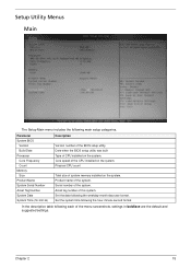
Date when the BIOS setup utility was built Type of the menu screenshots, settings in boldface are the default and suggested settings. Set the date following each of CPU installed on the system. Asset tag number of the BIOS setup utility. In the descriptive table following the weekday-month-day-year format. Set the system time following main setup categories. Setup Utility Menus Main The Setup Main menu includes the following the...
Date when the BIOS setup utility was built Type of the menu screenshots, settings in boldface are the default and suggested settings. Set the date following each of CPU installed on the system. Asset tag number of the BIOS setup utility. In the descriptive table following the weekday-month-day-year format. Set the system time following main setup categories. Setup Utility Menus Main The Setup Main menu includes the following the...
Acer Aspire M3420 Desktop Service Guide
Page 27
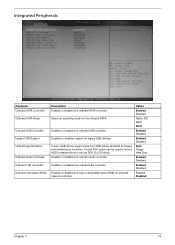
... used to force a HDD formatted drive to boot as harddrive. Forced FDD option can be emulated as Floppy and remaining as FDD (Ex.ZIP drive). Enables or disables the load of embedded option ROM for the onboard SATA. Enables or disables the onboard audio controller. Enables or disables the onboard USB controller. Enables or disables the onboard LAN controller. Select an operating mode for onboard network controller. Enables or disables support for legacy USB devices. Option Enabled Disabled Native IDE RAID AHCI Enabled Disabled Enabled Disabled Auto Floppy Hard Disk Enabled...
... used to force a HDD formatted drive to boot as harddrive. Forced FDD option can be emulated as Floppy and remaining as FDD (Ex.ZIP drive). Enables or disables the load of embedded option ROM for the onboard SATA. Enables or disables the onboard audio controller. Enables or disables the onboard USB controller. Enables or disables the onboard LAN controller. Select an operating mode for onboard network controller. Enables or disables support for legacy USB devices. Option Enabled Disabled Native IDE RAID AHCI Enabled Disabled Enabled Disabled Auto Floppy Hard Disk Enabled...
Acer Aspire M3420 Desktop Service Guide
Page 31
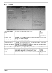
... diagnostic screen displays during the POST. Boot Options 1st/2nd/3rd/4th/5th Boot Device EFI Device Priority Hard Disk Drive Priority Optical Disk Drive Priority Removable Device Priority Network Device Priority Quiet Boot Halt On Specifies the boot order from available removable drives. Press Enter to access the Network Device Priority submenu and specify the boot device priority sequence from available optical drives. Enabled Disabled Determines whether the system will stop for an error during startup. EFI Hard Disk CD^DVD Removable Device LAN Press Enter to access the Hard Disk...
... diagnostic screen displays during the POST. Boot Options 1st/2nd/3rd/4th/5th Boot Device EFI Device Priority Hard Disk Drive Priority Optical Disk Drive Priority Removable Device Priority Network Device Priority Quiet Boot Halt On Specifies the boot order from available removable drives. Press Enter to access the Network Device Priority submenu and specify the boot device priority sequence from available optical drives. Enabled Disabled Determines whether the system will stop for an error during startup. EFI Hard Disk CD^DVD Removable Device LAN Press Enter to access the Hard Disk...
Acer Aspire M3420 Desktop Service Guide
Page 81
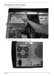
Reinstalling the Power Supply 1. Secure the power supply to chassis. 2. Chapter 3 73 Install the power supply to the chassis using four screws.
Reinstalling the Power Supply 1. Secure the power supply to chassis. 2. Chapter 3 73 Install the power supply to the chassis using four screws.

Acer Aspire M3420 Desktop Service Guide
Page 98
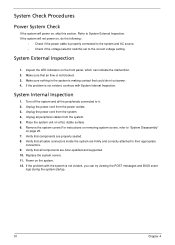
... 91 and "Beep Codes" on how to troubleshoot system hardware problems. Hardware Diagnostic Procedure IMPORTANT:The diagnostic tests described in as much detail as possible. 2. Obtain the failing symptoms in this chapter are only intended to test Acer products. Verify the symptoms by attempting to recreate the failure by running the diagnostic tests or repeating thesame operation. 3. NonAcerproducts, prototype cards, or modified options can give false errors and invalid...
... 91 and "Beep Codes" on how to troubleshoot system hardware problems. Hardware Diagnostic Procedure IMPORTANT:The diagnostic tests described in as much detail as possible. 2. Obtain the failing symptoms in this chapter are only intended to test Acer products. Verify the symptoms by attempting to recreate the failure by running the diagnostic tests or repeating thesame operation. 3. NonAcerproducts, prototype cards, or modified options can give false errors and invalid...
Acer Aspire M3420 Desktop Service Guide
Page 99
... all peripheral cables from the system. 5. Verify that could short out power. 4. Power on a flat, stable surface. 6. If the problem with System Internal Inspection. Make sure nothing in the system is making contact that all components are Acer-qualified and supported. 10. Place the system unit on the system. 12. Remove the system covers.For instructions on removing system covers, refer to System External Inspection...
... all peripheral cables from the system. 5. Verify that could short out power. 4. Power on a flat, stable surface. 6. If the problem with System Internal Inspection. Make sure nothing in the system is making contact that all components are Acer-qualified and supported. 10. Place the system unit on the system. 12. Remove the system covers.For instructions on removing system covers, refer to System External Inspection...
Acer Aspire M3420 Desktop Service Guide
Page 101
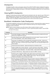
... change due to vendor requirements,system chipset or option ROMs from ROM to lower system memory and control is given to flat mode with 4GB limit and GA20 enabled. Go to it. Disable CACHE before system memory is done. Set stack. Bootblock code is copied from add-in debugging problems that flat mode is enabled. Both key sequence and OEM specific method is checked to checkpoint E0. If BIOS recovery...
... change due to vendor requirements,system chipset or option ROMs from ROM to lower system memory and control is given to flat mode with 4GB limit and GA20 enabled. Go to it. Disable CACHE before system memory is done. Set stack. Bootblock code is copied from add-in debugging problems that flat mode is enabled. Both key sequence and OEM specific method is checked to checkpoint E0. If BIOS recovery...
Acer Aspire M3420 Desktop Service Guide
Page 103
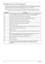
... 4 Restore CPUID value back into register. The following table describes the type of checkpoints that may differ between different platforms based on media. Recovery file not found flash part size. Disable ATAPI hardware. Bootblock Recovery Code Checkpoints The Bootblock recovery code gets control when the BIOS determines that a BIOS recovery needs to checkpoint EB. Enable ATAPI hardware. Jump back to occur because the user has forced the update or the BIOS checksum...
... 4 Restore CPUID value back into register. The following table describes the type of checkpoints that may differ between different platforms based on media. Recovery file not found flash part size. Disable ATAPI hardware. Bootblock Recovery Code Checkpoints The Bootblock recovery code gets control when the BIOS determines that a BIOS recovery needs to checkpoint EB. Enable ATAPI hardware. Jump back to occur because the user has forced the update or the BIOS checksum...
Acer Aspire M3420 Desktop Service Guide
Page 109
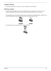
Setting Jumper Use the motherboard jumpers to set system configuration options. Jumpers with more Than one pin,the jumper is OPEN. Pins1 and 2 are Placed on the correct pins. The illustrations show a 2-pin jumper. Jumper Setting The section explains how to set jumper for correct configuration of the mainboard. Whenthe jumper cap is SHORT. If you remove the jumpercap, or place the jumper cap on both pins, thejumper is placed on just one pin are numbered. Chapter...
Setting Jumper Use the motherboard jumpers to set system configuration options. Jumpers with more Than one pin,the jumper is OPEN. Pins1 and 2 are Placed on the correct pins. The illustrations show a 2-pin jumper. Jumper Setting The section explains how to set jumper for correct configuration of the mainboard. Whenthe jumper cap is SHORT. If you remove the jumpercap, or place the jumper cap on both pins, thejumper is placed on just one pin are numbered. Chapter...


