
Service Guide
Page 7
... the Processor 32 Removing the Memory Modules 33 Removing the VGA Card 34 Removing the Mode Card 35 Removing the Front Bezel 36 Removing the Rear USB Board 37 Removing the Hard Disk Drive 38 Removing the Optical Drive 40 Removing the Cables 41 Removing the removable HDD bay 42 Removing the Power Supply 43 Removing the Mainboard 45 System Troubleshooting 47 System Check Procedures 48 Beep Codes 49 Checkpoints 50 BIOS Recovery 53 Jumper and Connector Information 54 M/B Placement 54 Setting Jumper 56 FRU (Field Replaceable Unit) List 67 Aspire M3400...
... the Processor 32 Removing the Memory Modules 33 Removing the VGA Card 34 Removing the Mode Card 35 Removing the Front Bezel 36 Removing the Rear USB Board 37 Removing the Hard Disk Drive 38 Removing the Optical Drive 40 Removing the Cables 41 Removing the removable HDD bay 42 Removing the Power Supply 43 Removing the Mainboard 45 System Troubleshooting 47 System Check Procedures 48 Beep Codes 49 Checkpoints 50 BIOS Recovery 53 Jumper and Connector Information 54 M/B Placement 54 Setting Jumper 56 FRU (Field Replaceable Unit) List 67 Aspire M3400...

Service Guide
Page 9
... model Need to measure VGA follow Acer SOP Audio • • Chip : HD audio codec ALC662-VC HD codec 5.1 Connectors support: • Rear 3 jack follow HD audio definition (ALC662-VC) • Audio jacks color coding: should meet Microsoft Windows Logo Program Device Requirements: Audio-0002 • 1 S/PDIF-out header (1*4) • 1 front panel audio header (2*5) • 1 internal speaker header (2*4) • Add HD de-pop CKT Serial ATA controller • Slot Type: SATA connector • Six SATA ports: • 4 for HDD...
... model Need to measure VGA follow Acer SOP Audio • • Chip : HD audio codec ALC662-VC HD codec 5.1 Connectors support: • Rear 3 jack follow HD audio definition (ALC662-VC) • Audio jacks color coding: should meet Microsoft Windows Logo Program Device Requirements: Audio-0002 • 1 S/PDIF-out header (1*4) • 1 front panel audio header (2*5) • 1 internal speaker header (2*4) • Add HD de-pop CKT Serial ATA controller • Slot Type: SATA connector • Six SATA ports: • 4 for HDD...
Service Guide
Page 10
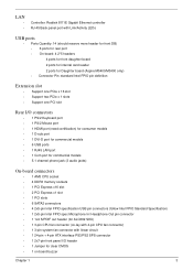
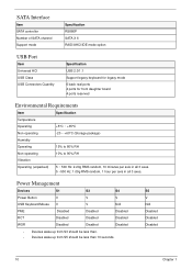
... controller RJ-45 Back panel port with Link/Activity LEDs USB ports • Ports Quantity: 14 (should reserve more header for front DB) • 6 ports for rear port • On-board: 4 2*5 headers 4 ports for front daughter board 2 ports for internal card reader 2 ports for Daughter board (Aspire M5400/M3400 only) • Connector Pin: standard Intel FPIO pin definition Extension slot • Support one PCIe x 16 slot • Support two PCIe x 1 slots • Support one PCI slot Rear I/O connectors • 1 PS/2 Keyboard port • 1 PS/2 Mouse port • 1 HDMI port (need...
... controller RJ-45 Back panel port with Link/Activity LEDs USB ports • Ports Quantity: 14 (should reserve more header for front DB) • 6 ports for rear port • On-board: 4 2*5 headers 4 ports for front daughter board 2 ports for internal card reader 2 ports for Daughter board (Aspire M5400/M3400 only) • Connector Pin: standard Intel FPIO pin definition Extension slot • Support one PCIe x 16 slot • Support two PCIe x 1 slots • Support one PCI slot Rear I/O connectors • 1 PS/2 Keyboard port • 1 PS/2 Mouse port • 1 HDMI port (need...

Service Guide
Page 13
Front Panel 8 1 7 6 2 3 4 5 No. System Components This section is a virtual tour of the system's interior and exterior components. Component 1 USB 2.0 ports 2 Acer logo 3 Optical drive button 4 Optical drive button (Removable HDD bay for AM351 bezel) 5 16 in 1 Card Reader 6 Power button 7 Headphone/Speaker-out/line-out jack 8 Microphone-in jack 6 Chapter 1
Front Panel 8 1 7 6 2 3 4 5 No. System Components This section is a virtual tour of the system's interior and exterior components. Component 1 USB 2.0 ports 2 Acer logo 3 Optical drive button 4 Optical drive button (Removable HDD bay for AM351 bezel) 5 16 in 1 Card Reader 6 Power button 7 Headphone/Speaker-out/line-out jack 8 Microphone-in jack 6 Chapter 1
Service Guide
Page 15
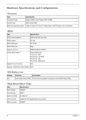
... Minimum operating speed 0 MHz (If Stop CPU Clock in Sleep State in BIOS Setup is set to Enabled.) BIOS Item Specification BIOS code programer AMI Kernel with Acer skin BIOS version P01-A0 BIOS ROM type SPI ROM BIOS ROM size 8Mb Support protocol SMBIOS(DMI)2.4/DMI2.0 Device Boot Support Support BBS spec 1st priority: HDD 2nd priority: CD-ROM 3th priority: LAN 4th priority: USB device Support to LS-120 drive YES Support to BIOS boot block feature YES IOS Hotkey List Hotkey Function Description Del Enter BIOS Setup Utility...
... Minimum operating speed 0 MHz (If Stop CPU Clock in Sleep State in BIOS Setup is set to Enabled.) BIOS Item Specification BIOS code programer AMI Kernel with Acer skin BIOS version P01-A0 BIOS ROM type SPI ROM BIOS ROM size 8Mb Support protocol SMBIOS(DMI)2.4/DMI2.0 Device Boot Support Support BBS spec 1st priority: HDD 2nd priority: CD-ROM 3th priority: LAN 4th priority: USB device Support to LS-120 drive YES Support to BIOS boot block feature YES IOS Hotkey List Hotkey Function Description Del Enter BIOS Setup Utility...
Service Guide
Page 16
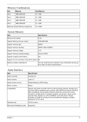
... System Memory Item Specification Memory slot number 4 slot Support Memory size per socket 1GB/2GB/4GB Support memory type DDRIII Support memory interface DDRIII 1066/1333MHz Support memory voltage 1.5V Support memory module package 240-pin DDRIII Support to parity check feature Yes Support to error correction code (ECC) feature No Memory module combinations You can install memory modules in any other HDA compatible audio controller. With EAX/Direct Sound 3D/I3DL2/ A3D compatibility, and excellent software utilities like environment sound...
... System Memory Item Specification Memory slot number 4 slot Support Memory size per socket 1GB/2GB/4GB Support memory type DDRIII Support memory interface DDRIII 1066/1333MHz Support memory voltage 1.5V Support memory module package 240-pin DDRIII Support to parity check feature Yes Support to error correction code (ECC) feature No Memory module combinations You can install memory modules in any other HDA compatible audio controller. With EAX/Direct Sound 3D/I3DL2/ A3D compatibility, and excellent software utilities like environment sound...
Service Guide
Page 17
...S3 S4 Power Button V V V USB Keyboard/Mouse V V N/A PME Disabled Disabled Disabled RCT Disabled Disabled Disabled WOR Disabled Disabled Disabled • Devices wake up from S3 should be less than. • Devices wake up from S5 should be less than 10 seconds. SATA Interface Item SATA controller Number of SATA channel Support mode Specification RS880P SATA X 6 RAID/AHCI/IDE mode option USB Port Item Universal HCI USB Class USB Connectors Quantity Specification USB 2.0/1.1 Support legacy keyboard for legacy mode 6 back real ports 4 ports for front daughter board 4 ports...
...S3 S4 Power Button V V V USB Keyboard/Mouse V V N/A PME Disabled Disabled Disabled RCT Disabled Disabled Disabled WOR Disabled Disabled Disabled • Devices wake up from S3 should be less than. • Devices wake up from S5 should be less than 10 seconds. SATA Interface Item SATA controller Number of SATA channel Support mode Specification RS880P SATA X 6 RAID/AHCI/IDE mode option USB Port Item Universal HCI USB Class USB Connectors Quantity Specification USB 2.0/1.1 Support legacy keyboard for legacy mode 6 back real ports 4 ports for front daughter board 4 ports...
Service Guide
Page 18
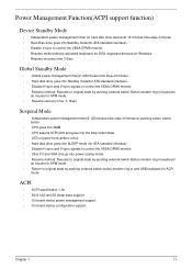
... in,keyboard an mouse for APM mode. • Resume recovery time :7-10sec Suspend Mode • Independent power management timer(2-120minutes,time step=10minute)or pushing extern switch button. • CPU goes into SMM • CPU asserts STPCLK# and goes into the Stop Grant State. • LED on panel turns amber colour. • Hard disk drive goes into SLEEP mode (for ATA standard interface). • Disable H-sync and V-sync signals to control the...
... in,keyboard an mouse for APM mode. • Resume recovery time :7-10sec Suspend Mode • Independent power management timer(2-120minutes,time step=10minute)or pushing extern switch button. • CPU goes into SMM • CPU asserts STPCLK# and goes into the Stop Grant State. • LED on panel turns amber colour. • Hard disk drive goes into SLEEP mode (for ATA standard interface). • Disable H-sync and V-sync signals to control the...
Service Guide
Page 19
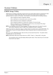
... RAM which allows configuration data to run this utility. The system reboots immediately after you have saved all open files. CMOS setup loads the configuration values in your system. NOTE: CMOS Setup Utility will need to run this utility under the following conditions. • When changing the system configuration settings • When redefining the communication ports to prevent any conflicts • When modifying the power management configuration • When changing the password or making other changes...
... RAM which allows configuration data to run this utility. The system reboots immediately after you have saved all open files. CMOS setup loads the configuration values in your system. NOTE: CMOS Setup Utility will need to run this utility under the following conditions. • When changing the system configuration settings • When redefining the communication ports to prevent any conflicts • When modifying the power management configuration • When changing the password or making other changes...
Service Guide
Page 21
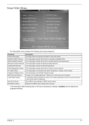
... This setup page includes all onboard peripherals This setup page includes all CMOS value changes and exit setup In the descriptive table following main setup categories. Chapter 2 14 Setup Utility Menus The Setup Main menu includes the following each of Green function features This setup page is the System auto detect Temperature, voltage, and fan speed This setup page is the System Frequency setup Change, set or disable password.
... This setup page includes all onboard peripherals This setup page includes all CMOS value changes and exit setup In the descriptive table following main setup categories. Chapter 2 14 Setup Utility Menus The Setup Main menu includes the following each of Green function features This setup page is the System auto detect Temperature, voltage, and fan speed This setup page is the System Frequency setup Change, set or disable password.

Service Guide
Page 22
... BIOS setup utility was released Asset tag number of the BIOS setup utility. Parameter Processor Type Processor Speed System Memory Product Name System Serial Number System BIOS Version BIOS Release Date Asset Tag Number Description Type of the system. These entries are for your reference only and are not user-configurable. Version number of this system. 15 Chapter 2 Total size of the system. Product name of system memory installed on the system. Serial number of CPU installed...
... BIOS setup utility was released Asset tag number of the BIOS setup utility. Parameter Processor Type Processor Speed System Memory Product Name System Serial Number System BIOS Version BIOS Release Date Asset Tag Number Description Type of the system. These entries are for your reference only and are not user-configurable. Version number of this system. 15 Chapter 2 Total size of the system. Product name of system memory installed on the system. Serial number of CPU installed...

Service Guide
Page 24
.../3rd/4th Boot Device Hard Disk Drive Priority Optical Disk Drives Priority Removable Device Priority Bootup Num-Lock USB Beep Message Description Option Allows you to decrease the time it takes to access the Hard Disk Drive Priority submenu and specify the boot device priority sequence from available removable drives. Selects power on state for Num Lock. Hard Disk CD^DVD Removable Device LAN Press Enter to boot the computer by shortening Enabled or skipping certain standard booting process. When disabled, the diagnostic screen displays during startup.
.../3rd/4th Boot Device Hard Disk Drive Priority Optical Disk Drives Priority Removable Device Priority Bootup Num-Lock USB Beep Message Description Option Allows you to decrease the time it takes to access the Hard Disk Drive Priority submenu and specify the boot device priority sequence from available removable drives. Selects power on state for Num Lock. Hard Disk CD^DVD Removable Device LAN Press Enter to boot the computer by shortening Enabled or skipping certain standard booting process. When disabled, the diagnostic screen displays during startup.

Service Guide
Page 26
...disables the onboard LAN controller. Enables or disables support for legacy USB devices. Enables or disables support for legacy USB devices. Enables or disables the onboard Floppy controller. Select an operating mode for onboard network controller. Integrated Peripherals Parameter Onboard SATA Controller Onboard SATA Mode Onboard USB Controller Legacy USB Support USB Storage Emulation Onboard Graphics Controller Onboard Graphics Mode Onboard Audio Controller Onboard LAN Controller Onboard LAN Option ROM Onboard Floppy Controller Serial Port1 Address Serial Port1 Mode Serial...
...disables the onboard LAN controller. Enables or disables support for legacy USB devices. Enables or disables support for legacy USB devices. Enables or disables the onboard Floppy controller. Select an operating mode for onboard network controller. Integrated Peripherals Parameter Onboard SATA Controller Onboard SATA Mode Onboard USB Controller Legacy USB Support USB Storage Emulation Onboard Graphics Controller Onboard Graphics Mode Onboard Audio Controller Onboard LAN Controller Onboard LAN Option ROM Onboard Floppy Controller Serial Port1 Address Serial Port1 Mode Serial...

Service Guide
Page 54
... test Acer products. NonAcerproducts, prototype cards, or modified options can give false errors and invalid systemresponses. 1. Chapter 4 47 Refer to "Power System check" and "Beep Codes" to determine which corrective action to recreate the failure by running the diagnostic tests or repeating thesame operation. 3. Verify the symptoms by attempting to perform. Chapter 4 System Troubleshooting This chapter provides instructions on how to troubleshoot system hardware problems. Hardware Diagnostic Procedure IMPORTANT:The diagnostic tests...
... test Acer products. NonAcerproducts, prototype cards, or modified options can give false errors and invalid systemresponses. 1. Chapter 4 47 Refer to "Power System check" and "Beep Codes" to determine which corrective action to recreate the failure by running the diagnostic tests or repeating thesame operation. 3. Verify the symptoms by attempting to perform. Chapter 4 System Troubleshooting This chapter provides instructions on how to troubleshoot system hardware problems. Hardware Diagnostic Procedure IMPORTANT:The diagnostic tests...

Service Guide
Page 55
... is making contact that all cable connectors inside the system are firmly and correctly attached to their appropriate connectors. 9. Verify that could short out power. 4. Unplug all the peripherals connected to System External Inspection. System Check Procedures Power System Check If the system will not power on removing system covers, refer to the correct voltage setting. If the problem with System Internal Inspection. Inspect the LED...
... is making contact that all cable connectors inside the system are firmly and correctly attached to their appropriate connectors. 9. Verify that could short out power. 4. Unplug all the peripherals connected to System External Inspection. System Check Procedures Power System Check If the system will not power on removing system covers, refer to the correct voltage setting. If the problem with System Internal Inspection. Inspect the LED...

Service Guide
Page 56
... fatal error to the end user. Not all computers using AMIBIOS enable this feature. Beep Symptom One short beep Continuous one long beep One long beep and two short beeps then repeat. System is damaged, BIOS POST jumps to Boot Block to as the PC speaker. Graphics card error/not installed, graphics card memory error or graphics card BIOS checksum error. BIOS damaged. CMOS checksum error or CMOS battery loss occurs. Beep codes are used when an error occurs before the system video has...
... fatal error to the end user. Not all computers using AMIBIOS enable this feature. Beep Symptom One short beep Continuous one long beep One long beep and two short beeps then repeat. System is damaged, BIOS POST jumps to Boot Block to as the PC speaker. Graphics card error/not installed, graphics card memory error or graphics card BIOS checksum error. BIOS damaged. CMOS checksum error or CMOS battery loss occurs. Beep codes are used when an error occurs before the system video has...

Service Guide
Page 57
.... Early super I /O port 80h on CPUID value in cards that occur during the bootblock initialization portion of I /O initialization is disabled. NMI is done including RTC and keyboard controller. Perform keyboard controller BAT test. Go to execute serial flash. Do additional chipset initialization. Copies BIOS from this point. Performs main BIOS checksum and updates recovery status accordingly. Store the Uncompressed pointer for future use in Boot block code.
.... Early super I /O port 80h on CPUID value in cards that occur during the bootblock initialization portion of I /O initialization is disabled. NMI is done including RTC and keyboard controller. Perform keyboard controller BAT test. Go to execute serial flash. Do additional chipset initialization. Copies BIOS from this point. Performs main BIOS checksum and updates recovery status accordingly. Store the Uncompressed pointer for future use in Boot block code.
Service Guide
Page 59
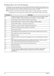
... the type of the BIOS. L1 cache is initialized. The flash has been updated successfully. Disable ATAPI hardware. Bootblock Recovery Code Checkpoints The Bootblock recovery code gets control when the BIOS determines that a BIOS recovery needs to vendor requirements, system chipset or option ROMs from add-in PCI devices. Checkpoints maychange due to occur because the user has forced the update or the BIOS checksum is corrupt. Set up floppy controller and data. Start reading the recovery...
... the type of the BIOS. L1 cache is initialized. The flash has been updated successfully. Disable ATAPI hardware. Bootblock Recovery Code Checkpoints The Bootblock recovery code gets control when the BIOS determines that a BIOS recovery needs to vendor requirements, system chipset or option ROMs from add-in PCI devices. Checkpoints maychange due to occur because the user has forced the update or the BIOS checksum is corrupt. Set up floppy controller and data. Start reading the recovery...
Service Guide
Page 63
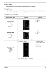
Internal header pin definition Jumper/Header Name CPU_FAN (3 PIN) Header_1X3 1 2 3 CPU_FAN Function CPU FAN HEADER Definition 1: SENSE 2: POWER 3: GND SYS_FAN (3 PIN) SYS FAN HEADER 1: SENSE 2: POWER 3: GND CLR_CMOS (3 PIN) Yellow is symbol, Red is Pin 1 of symbol. Chapter 5 56 Jumper Setting The section explains how to set jumper for correct configuration of the mainboard. When setting the jumpers, ensure that the jumper caps are numbered. Setting Jumper Use the motherboard jumpers to set system configuration options. CLEAR CMOS HEADER 1-2:CLEAR_CMOS (1:Ground, ...
Internal header pin definition Jumper/Header Name CPU_FAN (3 PIN) Header_1X3 1 2 3 CPU_FAN Function CPU FAN HEADER Definition 1: SENSE 2: POWER 3: GND SYS_FAN (3 PIN) SYS FAN HEADER 1: SENSE 2: POWER 3: GND CLR_CMOS (3 PIN) Yellow is symbol, Red is Pin 1 of symbol. Chapter 5 56 Jumper Setting The section explains how to set jumper for correct configuration of the mainboard. When setting the jumpers, ensure that the jumper caps are numbered. Setting Jumper Use the motherboard jumpers to set system configuration options. CLEAR CMOS HEADER 1-2:CLEAR_CMOS (1:Ground, ...

Service Guide
Page 74
... the FRU (Field Replaceable Unit) list in the FRU list of the Aspire M3400(G) desktop computer. NOTES: • When ordering FRU parts, check the most up-to-date information available on your regional Acer office on how to dispose it properly, or follow the rules set by your regional web or channel. For whatever reasons a part number is changed, it . • This...
... the FRU (Field Replaceable Unit) list in the FRU list of the Aspire M3400(G) desktop computer. NOTES: • When ordering FRU parts, check the most up-to-date information available on your regional Acer office on how to dispose it properly, or follow the rules set by your regional web or channel. For whatever reasons a part number is changed, it . • This...


