
Quick Start Guide
Page 7
...Touch-sensitive pointing device which functions like and right) the left and right buttons function like a computer mouse. 7 Power indicator1 Indicates the computer's power status. Fully charged: The light shows blue when in AC mode. 8 Click buttons (left The left and right... mouse buttons. 9 Palmrest Comfortable support area for recording sound. 1. Communication indicator Indicates the computer's wireless connectivity device status. 4 Power button Turns the computer on the model purchased. The front panel indicators are visible even when the computer cover is charging. 2....
...Touch-sensitive pointing device which functions like and right) the left and right buttons function like a computer mouse. 7 Power indicator1 Indicates the computer's power status. Fully charged: The light shows blue when in AC mode. 8 Click buttons (left The left and right... mouse buttons. 9 Palmrest Comfortable support area for recording sound. 1. Communication indicator Indicates the computer's wireless connectivity device status. 4 Power button Turns the computer on the model purchased. The front panel indicators are visible even when the computer cover is charging. 2....
Quick Start Guide
Page 8
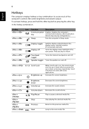
... a selected media file. To activate hotkeys, press and hold the key before pressing the other key in Sleep mode. + + + + Display toggle Display off to save power.
... a selected media file. To activate hotkeys, press and hold the key before pressing the other key in Sleep mode. + + + + Display toggle Display off to save power.
Service Guide
Page 3
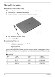
....00F87.735 86.00F80.723 86.9A524.4R0 86.00H36.534 86.00E12.536 28 Chapter 3 Turn off the power to any of the sequence to avoid damage to the system and all power and signal cables from the system. 3. Unplug the AC adapter and all peripherals. 2. Observe the order of the...
....00F87.735 86.00F80.723 86.9A524.4R0 86.00H36.534 86.00E12.536 28 Chapter 3 Turn off the power to any of the sequence to avoid damage to the system and all power and signal cables from the system. 3. Unplug the AC adapter and all peripherals. 2. Observe the order of the...
Service Guide
Page 20
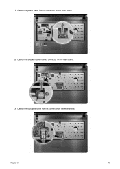
Chapter 3 45 Detach the touchpad cable from its connector on the main board. 13. Detach the speaker cable from its connector on the main board. Detach the power cable from its connector on the main board. 12. 11.
Chapter 3 45 Detach the touchpad cable from its connector on the main board. 13. Detach the speaker cable from its connector on the main board. Detach the power cable from its connector on the main board. 12. 11.
Service Guide
Page 27
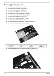
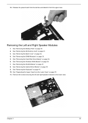
...Torque 1. 6 kgf-cm Part No. 86.00F80.723 12. See "Removing the Back Cover" on page 44. 11. See "Separating the Upper Case from the power board. 52 Chapter 3 See "Removing the WLAN Module" on page 30. 2. See "Removing the Battery Pack" on page 37. 8. See "Removing the Hard Disk... Drive Module" on page 36. 7. Release the latch and disconnect the the power cable from the Lower Case" on page 32. 4. See "Removing the Wireless WAN Module" on page 34. 6. Remove the one screw (B) securing the...
...Torque 1. 6 kgf-cm Part No. 86.00F80.723 12. See "Removing the Back Cover" on page 44. 11. See "Separating the Upper Case from the power board. 52 Chapter 3 See "Removing the WLAN Module" on page 30. 2. See "Removing the Battery Pack" on page 37. 8. See "Removing the Hard Disk... Drive Module" on page 36. 7. Release the latch and disconnect the the power cable from the Lower Case" on page 32. 4. See "Removing the Wireless WAN Module" on page 34. 6. Remove the one screw (B) securing the...
Service Guide
Page 28
... the lower case. Chapter 3 53 See "Removing the Back Cover" on page 44. 11. See "Removing the DIMM Modules" on page 39. 9. 13. Release the power board from the latches and detach it from the Lower Case" on page 32. 4. Removing the Left and Right Speaker Modules 1. See "Removing the Optical...
... the lower case. Chapter 3 53 See "Removing the Back Cover" on page 44. 11. See "Removing the DIMM Modules" on page 39. 9. 13. Release the power board from the latches and detach it from the Lower Case" on page 32. 4. Removing the Left and Right Speaker Modules 1. See "Removing the Optical...


