Acer Aspire 7736, Aspire 7736Z Notebook Series Start Guide
Page 3
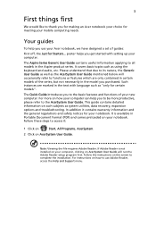
... 1 Click on Start, All Programs, AcerSystem. 2 Click on such subjects as using the keyboard and audio, etc. Please understand that due to all models in the text with setting up your ...... Note: Viewing the file requires Adobe Reader. Follow the instructions on how your notebook. The Aspire Series Generic User Guide contains useful information applying to its nature, the Generic User Guide as well... as "only for your computer can help you for making an Acer notebook your choice for meeting your mobile computing needs. poster helps you purchased. For more...
... 1 Click on Start, All Programs, AcerSystem. 2 Click on such subjects as using the keyboard and audio, etc. Please understand that due to all models in the text with setting up your ...... Note: Viewing the file requires Adobe Reader. Follow the instructions on how your notebook. The Aspire Series Generic User Guide contains useful information applying to its nature, the Generic User Guide as well... as "only for your computer can help you for making an Acer notebook your choice for meeting your mobile computing needs. poster helps you purchased. For more...
Acer Aspire 7736, Aspire 7736Z Notebook Series Start Guide
Page 5
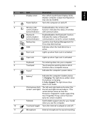
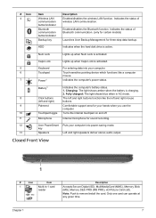
Caps Lock Lights up when Num Lock is activated. 5 Keyboard For entering data into your hands when you use the computer. 10 Touchpad toggle Turns the internal touchpad on and off . 11 Microphone .../indicator LAN communication. HDD Indicates when the hard disk drive is charging. 2. Num Lock Lights up when Caps Lock is activated. Protection fingerprint reader supporting Acer FingerNav 4-way control function (only for certain models). 9 Palmrest Comfortable support area for your computer. 6 Touchpad Touch-sensitive pointing device which functions like center...
Caps Lock Lights up when Num Lock is activated. 5 Keyboard For entering data into your hands when you use the computer. 10 Touchpad toggle Turns the internal touchpad on and off . 11 Microphone .../indicator LAN communication. HDD Indicates when the hard disk drive is charging. 2. Num Lock Lights up when Caps Lock is activated. Protection fingerprint reader supporting Acer FingerNav 4-way control function (only for certain models). 9 Palmrest Comfortable support area for your computer. 6 Touchpad Touch-sensitive pointing device which functions like center...
Acer Aspire 7736, Aspire 7736Z Notebook Series Start Guide
Page 12
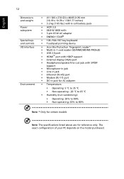
... battery pack • ACPI 3.0 • 48.8 W 4400 mAh • 3-pin 65 W AC adapter • ENERGY STAR® • 103-/104-/107-key keyboard • Touchpad pointing device • Acer Bio-Protection fingerprint reader* • Multi-in-1 card reader (SD/MMC/MS/MS PRO/xD) • USB 2.0 port • HDMI™ port with...
... battery pack • ACPI 3.0 • 48.8 W 4400 mAh • 3-pin 65 W AC adapter • ENERGY STAR® • 103-/104-/107-key keyboard • Touchpad pointing device • Acer Bio-Protection fingerprint reader* • Multi-in-1 card reader (SD/MMC/MS/MS PRO/xD) • USB 2.0 port • HDMI™ port with...
Service Guide
Page 7
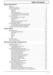
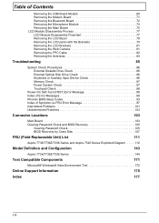
... Contents System Specifications 1 Features 1 System Block Diagram 4 Your Acer Notebook tour 6 Right View 9 Indicators 10 Easy-Launch Buttons 11 Touchpad Basics (with fingerprint reader 11 Touchpad basics (with two-click buttons 12 Using the Keyboard 13 Lock Keys and numeric keypad 13 Windows Keys 14 Hot... Keys 15 Special Key (only for certain models 15 Windows Mobility Center 16 Using the System Utilities 17 Acer Bio-Protection (only for certain models 17 Acer GridVista (dual-display ...
... Contents System Specifications 1 Features 1 System Block Diagram 4 Your Acer Notebook tour 6 Right View 9 Indicators 10 Easy-Launch Buttons 11 Touchpad Basics (with fingerprint reader 11 Touchpad basics (with two-click buttons 12 Using the Keyboard 13 Lock Keys and numeric keypad 13 Windows Keys 14 Hot... Keys 15 Special Key (only for certain models 15 Windows Mobility Center 16 Using the System Utilities 17 Acer Bio-Protection (only for certain models 17 Acer GridVista (dual-display ...
Service Guide
Page 8
... 82 Removing the Antennas 84 Troubleshooting 85 System Check Procedures 86 External Diskette Drive Check 86 External Optical Disk Drive Check 86 Keyboard or Auxiliary Input Device Check 86 Memory Check 87 Power System Check 87 Touchpad Check 88 Power-On Self-Test (POST) ... Check 105 BIOS Recovery by Crisis Disk 107 FRU (Field Replaceable Unit) List 111 Aspire 7736/7736Z/7336 Series and Aspire 7540 Series Exploded Diagram . . . . .112 Model Definition and Configuration 143 Aspire 7736/7736Z/7336 Series 144 Test Compatible Components 171 Microsoft® Windows® Vista ...
... 82 Removing the Antennas 84 Troubleshooting 85 System Check Procedures 86 External Diskette Drive Check 86 External Optical Disk Drive Check 86 Keyboard or Auxiliary Input Device Check 86 Memory Check 87 Power System Check 87 Touchpad Check 88 Power-On Self-Test (POST) ... Check 105 BIOS Recovery by Crisis Disk 107 FRU (Field Replaceable Unit) List 111 Aspire 7736/7736Z/7336 Series and Aspire 7540 Series Exploded Diagram . . . . .112 Model Definition and Configuration 143 Aspire 7736/7736Z/7336 Series 144 Test Compatible Components 171 Microsoft® Windows® Vista ...
Service Guide
Page 10
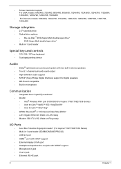
...• DVD-Super Multi double-layer drive* • Multi-in-1 card reader Special keys and controls • 103-/104-/107-key keyboard • Touchpad pointing device Audio • Dolby®-optimized surround sound system with S/PDIF support • Microphone-in jack • ...Line-in microphone Communication • Integrated Acer Crystal Eye webcam* • WLAN: • Intel® Wireless WiFi Link 5100/5300 (For Aspire 7736/7736Z/7336 Series) • Acer InviLink™ Nplify™ 802.11b/g/Draft-N* • Acer InviLink™ 802.11b/g* • WPAN: Bluetooth&#...
...• DVD-Super Multi double-layer drive* • Multi-in-1 card reader Special keys and controls • 103-/104-/107-key keyboard • Touchpad pointing device Audio • Dolby®-optimized surround sound system with S/PDIF support • Microphone-in jack • ...Line-in microphone Communication • Integrated Acer Crystal Eye webcam* • WLAN: • Intel® Wireless WiFi Link 5100/5300 (For Aspire 7736/7736Z/7336 Series) • Acer InviLink™ Nplify™ 802.11b/g/Draft-N* • Acer InviLink™ 802.11b/g* • WPAN: Bluetooth&#...
Service Guide
Page 15
Caps Lock Lights up when Num Lock is activated. 5 Keyboard For entering data into power-saving mode. key 13 Speakers Left and right speakers deliver stereo audio output. Battery1 Indicates the computer's battery status....the computer's power status. Enables/disables the Bluetooth function. Indicates the status of Bluetooth communication. (only for certain models) Launches Acer Backup Management for sound recording. 12 Acer PowerSmart Puts your computer into your hands when you use the computer. 10 Touchpad toggle Turns the internal touchpad on and off...
Caps Lock Lights up when Num Lock is activated. 5 Keyboard For entering data into power-saving mode. key 13 Speakers Left and right speakers deliver stereo audio output. Battery1 Indicates the computer's battery status....the computer's power status. Enables/disables the Bluetooth function. Indicates the status of Bluetooth communication. (only for certain models) Launches Acer Backup Management for sound recording. 12 Acer PowerSmart Puts your computer into your hands when you use the computer. 10 Touchpad toggle Turns the internal touchpad on and off...

Service Guide
Page 19
...-Protection fingerprint reader (3) supporting Acer FingerNav 4-way control function (only for three-step data backup. Tap twice (at the same speed as double-clicking a mouse button); Tapping on the right scroll bar of the keyboard are similar to the left (1) and right (4) buttons located beneath the touchpad to perform selection and execution...
...-Protection fingerprint reader (3) supporting Acer FingerNav 4-way control function (only for three-step data backup. Tap twice (at the same speed as double-clicking a mouse button); Tapping on the right scroll bar of the keyboard are similar to the left (1) and right (4) buttons located beneath the touchpad to perform selection and execution...
Service Guide
Page 21
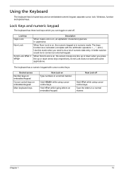
...numbers in uppercase. When Num Lock is on embedded keypad. Desired access Number keys on embedded keypad Cursor-control keys on embedded keypad Main keyboard keys Num Lock on , the numeric keypad is on and off Hold while using cursorcontrol keys. Type the letters in numeric mode. ... as a calculator (complete with the arithmetic operators +, -, *, and /). Hold while using cursorcontrol keys. Chapter 1 13 Lock Keys and numeric keypad The keyboard has three lock keys which you can toggle on , the screen moves one line up or down when you need to connect an external keypad...
...numbers in uppercase. When Num Lock is on embedded keypad. Desired access Number keys on embedded keypad Cursor-control keys on embedded keypad Main keyboard keys Num Lock on , the numeric keypad is on and off Hold while using cursorcontrol keys. Type the letters in numeric mode. ... as a calculator (complete with the arithmetic operators +, -, *, and /). Hold while using cursorcontrol keys. Chapter 1 13 Lock Keys and numeric keypad The keyboard has three lock keys which you can toggle on , the screen moves one line up or down when you need to connect an external keypad...
Service Guide
Page 22
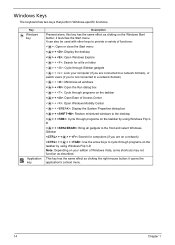
... the same effect as clicking the right mouse button; it opens the application's context menu. 14 Chapter 1 it launches the Start menu. Windows Keys The keyboard has two keys that perform Windows-specific functions.
... the same effect as clicking the right mouse button; it opens the application's context menu. 14 Chapter 1 it launches the Start menu. Windows Keys The keyboard has two keys that perform Windows-specific functions.
Service Guide
Page 23
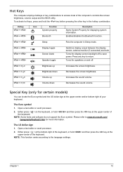
...Speaker toggle Switches display output between the display screen, external monitor (if connected) and both. Either press < > at the bottom-right of the keyboard. Press any key to the language settings. NOTE: This function varies according to return. The Euro symbol 1. Open a text editor or word processor...and off to save power. NOTE: Some fonts and software do not support the Euro symbol. Please refer to access most of your keyboard. To activate hot keys, press and hold and then press the key at the upper-center and/or bottom-right of the computer's...
...Speaker toggle Switches display output between the display screen, external monitor (if connected) and both. Either press < > at the bottom-right of the keyboard. Press any key to the language settings. NOTE: This function varies according to return. The Euro symbol 1. Open a text editor or word processor...and off to save power. NOTE: Some fonts and software do not support the Euro symbol. Please refer to access most of your keyboard. To activate hot keys, press and hold and then press the key at the upper-center and/or bottom-right of the computer's...

Service Guide
Page 33
... 17.3" WXGA+ Glare 0.204 x 0.204 R.G.B. System Board Major Chips Item Audio Codec Keyboard Item Keyboard controller Total number of keypads Windows logo key Internal & external keyboard work simultaneously Realtek ALC888s Controller Specification Winbond WPCE773 103-/104-/107-key keyboard Yes Plug USB keyboard to +60 AC Adaptor Item Input Specification 100-240V~ 1.5A, 50-60Hz...
... 17.3" WXGA+ Glare 0.204 x 0.204 R.G.B. System Board Major Chips Item Audio Codec Keyboard Item Keyboard controller Total number of keypads Windows logo key Internal & external keyboard work simultaneously Realtek ALC888s Controller Specification Winbond WPCE773 103-/104-/107-key keyboard Yes Plug USB keyboard to +60 AC Adaptor Item Input Specification 100-240V~ 1.5A, 50-60Hz...

Service Guide
Page 38
... on secondary IDE master. This field displays the serial number of HDD installed on secondary IDE master. Displays system BIOS version. This field shows the keyboard This field displays the serial number of the system. This field displays the VGA firmware version of the system. Parameter CPU Type CPU Speed IDE0...
... on secondary IDE master. This field displays the serial number of HDD installed on secondary IDE master. Displays system BIOS version. This field shows the keyboard This field displays the serial number of the system. This field displays the VGA firmware version of the system. Parameter CPU Type CPU Speed IDE0...
Service Guide
Page 50
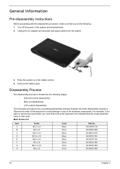
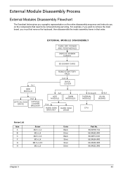
....3R5 86.9A552.3R0 42 Chapter 3 General Information Pre-disassembly Instructions Before proceeding with the disassembly procedure, make sure that you must first remove the keyboard, then disassemble the inside assembly frame in the succeeding disassembly sections illustrate the entire disassembly sequence. For example, if you want to remove the main...
....3R5 86.9A552.3R0 42 Chapter 3 General Information Pre-disassembly Instructions Before proceeding with the disassembly procedure, make sure that you must first remove the keyboard, then disassemble the inside assembly frame in the succeeding disassembly sections illustrate the entire disassembly sequence. For example, if you want to remove the main...
Service Guide
Page 51
... Disassembly Process External Modules Disassembly Flowchart The flowchart below gives you a graphic representation on the entire disassembly sequence and instructs you must first remove the keyboard, then disassemble the inside assembly frame in that need to be removed during servicing. EXTERNAL MODULE DISASSEMBLY TURN OFF POWER AND PERIPHERALS UNPLUG POWER CABLES...
... Disassembly Process External Modules Disassembly Flowchart The flowchart below gives you a graphic representation on the entire disassembly sequence and instructs you must first remove the keyboard, then disassemble the inside assembly frame in that need to be removed during servicing. EXTERNAL MODULE DISASSEMBLY TURN OFF POWER AND PERIPHERALS UNPLUG POWER CABLES...

Service Guide
Page 65
Main Unit Disassembly Process Main Unit Disassembly Flowchart MAIN UNIT DISASSEMBLY MAIN UNIT Cx12, Ax5, Gx1 LOWER CASE MIDDLE COVER MICROPHONE MODULE KEYBOARD Dx4 LCD MODULE Bx2, Cx4 UPPER CASE Fx1 MODEM CARD Ax1 USB MODULE Bx2 FINGERPRINT MODULE TOUCHPAD MODULE Screw List Item A B C G H Screw M2.5 x L4 M2 x L4 M2.5 x L6 M2.5 x L3.5 M2 x L3 Hx1 MAIN BOARD Color Black Silver Black Silver Silver Part No. 86.00H59.734 86.9A552.4R0 86.00E12.536 86.9A536.3R5 86.9A552.3R0 Chapter 3 57
Main Unit Disassembly Process Main Unit Disassembly Flowchart MAIN UNIT DISASSEMBLY MAIN UNIT Cx12, Ax5, Gx1 LOWER CASE MIDDLE COVER MICROPHONE MODULE KEYBOARD Dx4 LCD MODULE Bx2, Cx4 UPPER CASE Fx1 MODEM CARD Ax1 USB MODULE Bx2 FINGERPRINT MODULE TOUCHPAD MODULE Screw List Item A B C G H Screw M2.5 x L4 M2 x L4 M2.5 x L6 M2.5 x L3.5 M2 x L3 Hx1 MAIN BOARD Color Black Silver Black Silver Silver Part No. 86.00H59.734 86.9A552.4R0 86.00E12.536 86.9A536.3R5 86.9A552.3R0 Chapter 3 57
Service Guide
Page 68
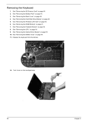
... "Removing the DIMM Module" on page 52. 8. See "Removing the Heatsink Module" on page 51. 7. Release the keyboard from the latches. 12. See "Removing the Battery Pack" on page 55. 10. Removing the Keyboard 1. See "Removing the Optical Drive Module" on page 45. 3. See "Removing the SD Dummy Card" on page 44...
... "Removing the DIMM Module" on page 52. 8. See "Removing the Heatsink Module" on page 51. 7. Release the keyboard from the latches. 12. See "Removing the Battery Pack" on page 55. 10. Removing the Keyboard 1. See "Removing the Optical Drive Module" on page 45. 3. See "Removing the SD Dummy Card" on page 44...

Service Guide
Page 69
See "Removing the Battery Pack" on page 60. 12. See "Removing the Keyboard" on page 45. 3. Chapter 3 61 Release the latch (a) and disconnect the keyboard cable (b) from the hole.. See "Removing the Back Cover" on the main board and detach the keyboard. See "Removing the Wireless LAN Card" on page 52. 8. See "Removing the...
See "Removing the Battery Pack" on page 60. 12. See "Removing the Keyboard" on page 45. 3. Chapter 3 61 Release the latch (a) and disconnect the keyboard cable (b) from the hole.. See "Removing the Back Cover" on the main board and detach the keyboard. See "Removing the Wireless LAN Card" on page 52. 8. See "Removing the...

Service Guide
Page 71
... Module" on page 48. 5. Carefully remove the LCD module from the base unit. See "Removing the Middle Cover" on page 60. 12. See "Removing the Keyboard" on page 58. 11. See "Removing the DIMM Module" on page 55. 10. See "Removing the Optical Drive Module" on page 51. 7.
... Module" on page 48. 5. Carefully remove the LCD module from the base unit. See "Removing the Middle Cover" on page 60. 12. See "Removing the Keyboard" on page 58. 11. See "Removing the DIMM Module" on page 55. 10. See "Removing the Optical Drive Module" on page 51. 7.

Service Guide
Page 74
... 45. 3. See "Separating the Upper Case from the fingerprint/ button board. 66 Chapter 3 See "Removing the Battery Pack" on page 55. 10. See "Removing the Keyboard" on page 52. 8. Removing the Fingerprint/Button and Touchpad Boards 1. See "Removing the Heatsink Module" on page 60. 12. See "Removing the CPU" on page...
... 45. 3. See "Separating the Upper Case from the fingerprint/ button board. 66 Chapter 3 See "Removing the Battery Pack" on page 55. 10. See "Removing the Keyboard" on page 52. 8. Removing the Fingerprint/Button and Touchpad Boards 1. See "Removing the Heatsink Module" on page 60. 12. See "Removing the CPU" on page...


