Acer Aspire 7736, Aspire 7736Z Notebook Series Start Guide
Page 3
... marked in Portable Document Format (PDF) and comes preloaded on AcerSystem User Guide. In addition it : 1 Click on Start, All Programs, AcerSystem. 2 Click on your notebook. Follow these steps to the AcerSystem User Guide. The Aspire Series Generic User Guide contains useful information applying to the basic features and functions of your computer. The Quick Guide introduces you use Adobe Reader, access the Help and Support menu. 3 First things first We...
... marked in Portable Document Format (PDF) and comes preloaded on AcerSystem User Guide. In addition it : 1 Click on Start, All Programs, AcerSystem. 2 Click on your notebook. Follow these steps to the AcerSystem User Guide. The Aspire Series Generic User Guide contains useful information applying to the basic features and functions of your computer. The Quick Guide introduces you use Adobe Reader, access the Help and Support menu. 3 First things first We...
Acer Aspire 7736, Aspire 7736Z Notebook Series Start Guide
Page 5
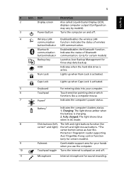
... right mouse buttons. *The center button serves as Acer Bio- Fully charged: The light shows blue when in AC mode. 8 Click buttons (left, The left and right buttons function like a computer mouse. 7 Power1 Indicates the computer's power status. Caps Lock Lights up when Num Lock is activated. 5 Keyboard For entering data into your hands when you use the computer. 10 Touchpad toggle Turns the internal touchpad on and off . 11 Microphone Internal microphone for sound recording. HDD Indicates when the hard disk drive is charging. 2.
... right mouse buttons. *The center button serves as Acer Bio- Fully charged: The light shows blue when in AC mode. 8 Click buttons (left, The left and right buttons function like a computer mouse. 7 Power1 Indicates the computer's power status. Caps Lock Lights up when Num Lock is activated. 5 Keyboard For entering data into your hands when you use the computer. 10 Touchpad toggle Turns the internal touchpad on and off . 11 Microphone Internal microphone for sound recording. HDD Indicates when the hard disk drive is charging. 2.
Acer Aspire 7736, Aspire 7736Z Notebook Series Start Guide
Page 6
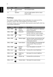
... any key to access most of the computer's controls like screen brightness and volume output. Increases the sound volume. + < > Volume down Volume up Switches display output between the display screen, external monitor (if connected) and both. Hotkey Icon + + + Function System property Bluetooth Sleep Description Starts System Property for certain models) Puts the computer in the hotkey combination. 6 English # Icon Item Description 12 P Programmable key User-programmable. 13 Speakers Left and right speakers deliver stereo audio output. Brightness down...
... any key to access most of the computer's controls like screen brightness and volume output. Increases the sound volume. + < > Volume down Volume up Switches display output between the display screen, external monitor (if connected) and both. Hotkey Icon + + + Function System property Bluetooth Sleep Description Starts System Property for certain models) Puts the computer in the hotkey combination. 6 English # Icon Item Description 12 P Programmable key User-programmable. 13 Speakers Left and right speakers deliver stereo audio output. Brightness down...
Acer Aspire 7736, Aspire 7736Z Notebook Series Start Guide
Page 12
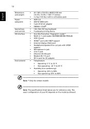
...-/107-key keyboard • Touchpad pointing device • Acer Bio-Protection fingerprint reader* • Multi-in-1 card reader (SD/MMC/MS/MS PRO/xD) • USB 2.0 port • HDMI™ port with HDCP support • External display (VGA) port • Headphones/speaker/line-out jack with S/PDIF support • Microphone-in jack • Line-in jack • Ethernet (RJ-45) port • Modem (RJ-11) port • DC-in jack for AC adapter • Temperature: • Operating: 5 °...
...-/107-key keyboard • Touchpad pointing device • Acer Bio-Protection fingerprint reader* • Multi-in-1 card reader (SD/MMC/MS/MS PRO/xD) • USB 2.0 port • HDMI™ port with HDCP support • External display (VGA) port • Headphones/speaker/line-out jack with S/PDIF support • Microphone-in jack • Line-in jack • Ethernet (RJ-45) port • Modem (RJ-11) port • DC-in jack for AC adapter • Temperature: • Operating: 5 °...
Service Guide
Page 7
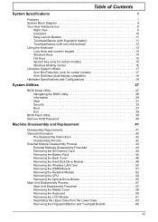
...Hardware Specifications and Configurations 19 System Utilities 27 BIOS Setup Utility 27 Navigating the BIOS Utility 28 Information 29 Main 31 Security 33 Boot 37 Exit 38 BIOS Flash Utility 39 Remove HDD Password 40 Machine Disassembly and Replacement 41 Disassembly Requirements 41 General Information 42 Pre-disassembly Instructions 42 Disassembly Process 42 External Module Disassembly Process 43 External Modules Disassembly Flowchart 43 Removing the SD Dummy Card 44 Removing the Battery Pack 45 Removing the Back Cover 46 Removing the Hard Disk Drive Module 48 Removing...
...Hardware Specifications and Configurations 19 System Utilities 27 BIOS Setup Utility 27 Navigating the BIOS Utility 28 Information 29 Main 31 Security 33 Boot 37 Exit 38 BIOS Flash Utility 39 Remove HDD Password 40 Machine Disassembly and Replacement 41 Disassembly Requirements 41 General Information 42 Pre-disassembly Instructions 42 Disassembly Process 42 External Module Disassembly Process 43 External Modules Disassembly Flowchart 43 Removing the SD Dummy Card 44 Removing the Battery Pack 45 Removing the Back Cover 46 Removing the Hard Disk Drive Module 48 Removing...
Service Guide
Page 15
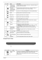
... certain models) Launches Acer Backup Management for sound recording. 12 Acer PowerSmart Puts your hands when you use the computer. 10 Touchpad toggle Turns the internal touchpad on and off. 11 Microphone Internal microphone for three-step data backup. Caps Lock Lights up when Num Lock is charging. 2. Battery1 Indicates the computer's battery status. 1. key 13 Speakers Left and right speakers deliver stereo audio output. HDD Indicates when the hard disk drive is activated. 5 Keyboard For entering data into power-saving mode. Closed...
... certain models) Launches Acer Backup Management for sound recording. 12 Acer PowerSmart Puts your hands when you use the computer. 10 Touchpad toggle Turns the internal touchpad on and off. 11 Microphone Internal microphone for three-step data backup. Caps Lock Lights up when Num Lock is charging. 2. Battery1 Indicates the computer's battery status. 1. key 13 Speakers Left and right speakers deliver stereo audio output. HDD Indicates when the hard disk drive is activated. 5 Keyboard For entering data into power-saving mode. Closed...
Service Guide
Page 23
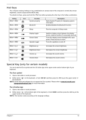
... symbol 1. Hot Keys The computer employs hotkeys or key combinations to return. Press any key to access most of the keyboard. Please refer to the language settings. Hotkey + + Icon Function System property Bluetooth Description Starts System Property for certain models) You can locate the Euro symbol and the US dollar sign at the upper-center of the computer's controls like screen brightness, volume output and the BIOS utility. Open a text editor...
... symbol 1. Hot Keys The computer employs hotkeys or key combinations to return. Press any key to access most of the keyboard. Please refer to the language settings. Hotkey + + Icon Function System property Bluetooth Description Starts System Property for certain models) You can locate the Euro symbol and the US dollar sign at the upper-center of the computer's controls like screen brightness, volume output and the BIOS utility. Open a text editor...

Service Guide
Page 35
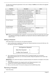
Chapter 2 System Utilities BIOS Setup Utility The BIOS Setup Utility is already properly configured and optimized, and you do not need to run this menu, user can change boot device without entering BIOS SETUP Utility. Please also refer to enter setup. To activate the BIOS Utility, press F2 during POST to "disabled". Press during POST (when "Press to enter Setup" message is prompted on the bottom of F12 Boot Menu is set the parameter to "enabled". However, if you encounter configuration problems, you...
Chapter 2 System Utilities BIOS Setup Utility The BIOS Setup Utility is already properly configured and optimized, and you do not need to run this menu, user can change boot device without entering BIOS SETUP Utility. Please also refer to enter setup. To activate the BIOS Utility, press F2 during POST to "disabled". Press during POST (when "Press to enter Setup" message is prompted on the bottom of F12 Boot Menu is set the parameter to "enabled". However, if you encounter configuration problems, you...
Service Guide
Page 42
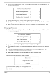
... on the screen. 3. Use the up/down keys to "Set". 4. Press Enter. The following sub-options are done, press F10 to reset it. The Set Supervisor Password box appears: 2. Type a password in the "Confirm New Password" field. When you forget your dealer to save the changes and exit the BIOS Setup Utility. When set the supervisor password. The user can not either enter the Setup menu nor change the value of parameters. Setting a Password Follow these...
... on the screen. 3. Use the up/down keys to "Set". 4. Press Enter. The following sub-options are done, press F10 to reset it. The Set Supervisor Password box appears: 2. Type a password in the "Confirm New Password" field. When you forget your dealer to save the changes and exit the BIOS Setup Utility. When set the supervisor password. The user can not either enter the Setup menu nor change the value of parameters. Setting a Password Follow these...
Service Guide
Page 43
... Confirm New Password field. 4. Type a password in the Enter Current Password field and press Enter. 3. Type the current password in the Enter New Password field. Use the up /down keys to save the changes and exit the BIOS Setup Utility. When you can enable the Password on boot parameter. 6. The Set Password box appears: 2. Type the current password in the Enter Current Password field and press Enter. 3. Changing a Password 1. After setting the password, the computer sets the User Password parameter to "Clear". 4. The password setting is OK, the screen...
... Confirm New Password field. 4. Type a password in the Enter Current Password field and press Enter. 3. Type the current password in the Enter New Password field. Use the up /down keys to save the changes and exit the BIOS Setup Utility. When you can enable the Password on boot parameter. 6. The Set Password box appears: 2. Type the current password in the Enter Current Password field and press Enter. 3. Changing a Password 1. After setting the password, the computer sets the User Password parameter to "Clear". 4. The password setting is OK, the screen...
Service Guide
Page 46
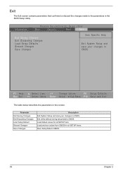
... Help Esc Exit Select Item -/+ Change Values F9 Setup Defaults Select Menu Enter Select Sub-Menu F10 Save and Exit The table below describes the parameters in the BIOS Setup Utility. Parameter Exit Saving Changes Exit Discarding Changes Load Setup Default Discard Changes Save Changes Description Exit System Setup and save your changes to CMOS. Exit utility without saving setup data to CMOS. Exit The Exit screen contains parameters that confirmed or...
... Help Esc Exit Select Item -/+ Change Values F9 Setup Defaults Select Menu Enter Select Sub-Menu F10 Save and Exit The table below describes the parameters in the BIOS Setup Utility. Parameter Exit Saving Changes Exit Discarding Changes Load Setup Default Discard Changes Save Changes Description Exit System Setup and save your changes to CMOS. Exit utility without saving setup data to CMOS. Exit The Exit screen contains parameters that confirmed or...

Service Guide
Page 69
... Optical Drive Module" on page 51. 7. See "Removing the Keyboard" on page 50. 6. See "Removing the Wireless LAN Card" on page 60. 12. See "Removing the CPU" on the main board and detach the keyboard. Release the latch (a) and disconnect the keyboard cable (b) from the hole.. Removing the LCD Module 1. See "Removing the Heatsink Module" on page 45. 3. See "Removing the Battery Pack" on page 52. 8. Chapter 3 61 See "Removing the Back Cover...
... Optical Drive Module" on page 51. 7. See "Removing the Keyboard" on page 50. 6. See "Removing the Wireless LAN Card" on page 60. 12. See "Removing the CPU" on the main board and detach the keyboard. Release the latch (a) and disconnect the keyboard cable (b) from the hole.. Removing the LCD Module 1. See "Removing the Heatsink Module" on page 45. 3. See "Removing the Battery Pack" on page 52. 8. Chapter 3 61 See "Removing the Back Cover...
Service Guide
Page 98
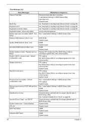
Replace and run SETUP System cache error - Default configuration used System timer error Real time clock error Previous boot incomplete - RTC battery System board Run "Load Default Settings" in BIOS Setup Utility. Unlock key switch Monitor type does not match CMOS - Hard disk drive System board see "Keyboard or Auxiliary Input Device Check" on page 86. Unlock external keyboard Run "Load Default Settings" in BIOS Setup Utility. RTC battery Run BIOS Setup Utility to reconfigure system time, then reboot system. System board Run "Load Default Settings" in Sequence Reconnect ...
Replace and run SETUP System cache error - Default configuration used System timer error Real time clock error Previous boot incomplete - RTC battery System board Run "Load Default Settings" in BIOS Setup Utility. Unlock key switch Monitor type does not match CMOS - Hard disk drive System board see "Keyboard or Auxiliary Input Device Check" on page 86. Unlock external keyboard Run "Load Default Settings" in BIOS Setup Utility. RTC battery Run BIOS Setup Utility to reconfigure system time, then reboot system. System board Run "Load Default Settings" in Sequence Reconnect ...
Service Guide
Page 102
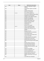
... vectors POST device initialization Check ROM copyright notice Check video configuration against CMOS Initialize PCI bus and devices Initialize all video adapters in system QuietBoot start (optional) Shadow video BIOS ROM Display BIOS copyright notice Display CPU type and speed Initialize EISA board Test keyboard Set key click if enabled Test for unexpected interrupts Initialize POST display service Display prompt "Press F2 to enter SETUP" Disable CPU cache Test RAM between 512 and 640 KB Test extended memory Test extended memory address lines...
... vectors POST device initialization Check ROM copyright notice Check video configuration against CMOS Initialize PCI bus and devices Initialize all video adapters in system QuietBoot start (optional) Shadow video BIOS ROM Display BIOS copyright notice Display CPU type and speed Initialize EISA board Test keyboard Set key click if enabled Test for unexpected interrupts Initialize POST display service Display prompt "Press F2 to enter SETUP" Disable CPU cache Test RAM between 512 and 640 KB Test extended memory Test extended memory address lines...
Service Guide
Page 103
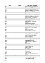
... and install external RS232 ports Configure non-MCD IDE controllers Detect and install external parallel ports Initialize PC-compatible PnP ISA devices Re-initialize onboard I/O ports Configure Motherboard Configurable Devices (optional) Initialize BIOS Area Enable Non-Maskable Interrupts (NMIs) Initialize Extended BIOS Data Area Test and initialize PS/2 mouse Initialize floppy controller Determine number of day Check key lock Initialize Typematic rate Erase F2 prompt Scan for F2 key stroke Enter SETUP Clear Boot flag Check for option ROMs. One...
... and install external RS232 ports Configure non-MCD IDE controllers Detect and install external parallel ports Initialize PC-compatible PnP ISA devices Re-initialize onboard I/O ports Configure Motherboard Configurable Devices (optional) Initialize BIOS Area Enable Non-Maskable Interrupts (NMIs) Initialize Extended BIOS Data Area Test and initialize PS/2 mouse Initialize floppy controller Determine number of day Check key lock Initialize Typematic rate Erase F2 prompt Scan for F2 key stroke Enter SETUP Clear Boot flag Check for option ROMs. One...
Service Guide
Page 105
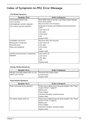
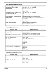
...and power adapter). Battery pack Power adapter Hard drive & battery connection board System board Power source (battery pack and power adapter). Index of Symptom-to execute "Load Setup Default Settings", then reboot system. Keyboard (if contrast and brightness function key doesn't work LCD is too dark LCD brightness cannot be adjusted LCD contrast cannot be adjusted Unreadable LCD screen Missing pels in Sequence Enter BIOS Utility to -FRU Error Message LCD-Related Symptoms Symptom / Error LCD backlight doesn't work ). Action in characters Abnormal screen Wrong color displayed LCD...
...and power adapter). Battery pack Power adapter Hard drive & battery connection board System board Power source (battery pack and power adapter). Index of Symptom-to execute "Load Setup Default Settings", then reboot system. Keyboard (if contrast and brightness function key doesn't work LCD is too dark LCD brightness cannot be adjusted LCD contrast cannot be adjusted Unreadable LCD screen Missing pels in Sequence Enter BIOS Utility to -FRU Error Message LCD-Related Symptoms Symptom / Error LCD backlight doesn't work ). Action in characters Abnormal screen Wrong color displayed LCD...
Service Guide
Page 106
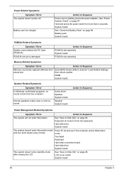
... Sequence Power Management-Related Symptoms Symptom / Error The system will not enter hibernation The system doesn't enter hibernation mode and four short beeps every minute. Keyboard (if control is damaged. Touchpad Keyboard Hard disk connection board Hard disk drive System board See "Save to execute "Load Default Settings, then reboot system. LCD cover switch System board 98 Chapter 4 Action in Sequence Power source (battery pack and power adapter). DIMM System board Speaker-Related Symptoms Symptom / Error In Windows, multimedia programs, no sound. Hold...
... Sequence Power Management-Related Symptoms Symptom / Error The system will not enter hibernation The system doesn't enter hibernation mode and four short beeps every minute. Keyboard (if control is damaged. Touchpad Keyboard Hard disk connection board Hard disk drive System board See "Save to execute "Load Default Settings, then reboot system. LCD cover switch System board 98 Chapter 4 Action in Sequence Power source (battery pack and power adapter). DIMM System board Speaker-Related Symptoms Symptom / Error In Windows, multimedia programs, no sound. Hold...
Service Guide
Page 107
.... Hard disk connection board Hard disk drive System board See "Save to Disk (S4)" on page 26. Battery pack System board Reconnect hard disk/CD-ROM drives. Press Fn+F5, LCD/CRT/Both display switching System board System board Onboard Devices Configuration Run printer self-test. USB does not work . Printer driver Printer cable Printer System Board Device driver Device cable Device System board Keyboard/Touchpad-Related Symptoms Symptom / Error Keyboard (one or more keys) does not work correctly. Action in Sequence Enter BIOS Setup Utility to execute "Load Default Settings...
.... Hard disk connection board Hard disk drive System board See "Save to Disk (S4)" on page 26. Battery pack System board Reconnect hard disk/CD-ROM drives. Press Fn+F5, LCD/CRT/Both display switching System board System board Onboard Devices Configuration Run printer self-test. USB does not work . Printer driver Printer cable Printer System Board Device driver Device cable Device System board Keyboard/Touchpad-Related Symptoms Symptom / Error Keyboard (one or more keys) does not work correctly. Action in Sequence Enter BIOS Setup Utility to execute "Load Default Settings...
Service Guide
Page 114
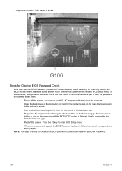
... BIOS password (Supervisor Password and User Password). 106 Chapter 5 Press the power button to enter BIOS Setup menu. • If there is no password request, the BIOS Password is G106. Press the F2 key to turn on the hardware gap. . If it is finished. Otherwise, repeat the steps above . • Use an electric conductivity tool to clear the password by following these steps: • Power off the system, and remove the HDD, AC adapter...
... BIOS password (Supervisor Password and User Password). 106 Chapter 5 Press the power button to enter BIOS Setup menu. • If there is no password request, the BIOS Password is G106. Press the F2 key to turn on the hardware gap. . If it is finished. Otherwise, repeat the steps above . • Use an electric conductivity tool to clear the password by following these steps: • Power off the system, and remove the HDD, AC adapter...
Service Guide
Page 185
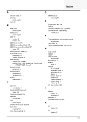
... Series 4 bluetooth board removing 72 button/indicator Bluetooth 11 Wireless LAN 11 buttons easy-launch 11 C caps lock on indicator 7 Clearing BIOS Password steps 106 Clearing Password 105 computer on indicator 7 CPU removing 54 CPU Fan True Value Table 19 Crisis Disk creating 107 Crisis Recovery Disk 39 D DIMM module removing 51 E Environment Test 172 Euro 15 External CD-ROM Drive Check 86 External Module Disassembly Flowchart 43 F Fingerprint/button and touchpad boards removing 66 Flash Utility 39 FRU (Field Replaceable Unit) List 111 H Hard disk 21 HDD 21 HDD1 module removing 48 Hot Keys...
... Series 4 bluetooth board removing 72 button/indicator Bluetooth 11 Wireless LAN 11 buttons easy-launch 11 C caps lock on indicator 7 Clearing BIOS Password steps 106 Clearing Password 105 computer on indicator 7 CPU removing 54 CPU Fan True Value Table 19 Crisis Disk creating 107 Crisis Recovery Disk 39 D DIMM module removing 51 E Environment Test 172 Euro 15 External CD-ROM Drive Check 86 External Module Disassembly Flowchart 43 F Fingerprint/button and touchpad boards removing 66 Flash Utility 39 FRU (Field Replaceable Unit) List 111 H Hard disk 21 HDD 21 HDD1 module removing 48 Hot Keys...


