Acer Aspire 7535 Notebook Service Guide
Page 8
... Drive Check 96 External Optical Disk Drive Check 96 Keyboard or Auxiliary Input Device Check 96 Memory Check 97 Power System Check 97 Touchpad Check 98 Power-On Self-Test (POST) Error Message 98 Index of Error Messages 99 Phoenix BIOS Beep Codes 103 Index...117 FRU (Field Replaceable Unit) List 121 Aspire 7738/7738G Series, Aspire7735/7735G/7735Z/7735ZG Series and Aspire 7535/7535G/7235 Series Exploded Diagram 122 Model Definition and Configuration 183 Aspire 7738/7738G Series 184 Aspire 7735/7735G/7735Z/7735ZG Series 193 Aspire 7535/7535G/7235 Series 198 Test Compatible ...
... Drive Check 96 External Optical Disk Drive Check 96 Keyboard or Auxiliary Input Device Check 96 Memory Check 97 Power System Check 97 Touchpad Check 98 Power-On Self-Test (POST) Error Message 98 Index of Error Messages 99 Phoenix BIOS Beep Codes 103 Index...117 FRU (Field Replaceable Unit) List 121 Aspire 7738/7738G Series, Aspire7735/7735G/7735Z/7735ZG Series and Aspire 7535/7535G/7235 Series Exploded Diagram 122 Model Definition and Configuration 183 Aspire 7738/7738G Series 184 Aspire 7735/7735G/7735Z/7735ZG Series 193 Aspire 7535/7535G/7235 Series 198 Test Compatible ...
Acer Aspire 7535 Notebook Service Guide
Page 14
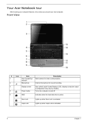
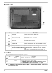
Front View # Icon Item Description 1 Acer Crystal Eye Web camera for sound recording. 3 Display screen Also called Liquid-Crystal Display (LCD), displays computer output (Configuration may vary by models). 4 Power button Turns the computer on and off. 5 HDD Indicates when the hard disk drive is ...active. Lights up when Num Lock is activated. 6 Chapter 1 Num Lock Caps Lock Lights up when Caps Lock is activated. Your Acer Notebook tour After knowing ...
Front View # Icon Item Description 1 Acer Crystal Eye Web camera for sound recording. 3 Display screen Also called Liquid-Crystal Display (LCD), displays computer output (Configuration may vary by models). 4 Power button Turns the computer on and off. 5 HDD Indicates when the hard disk drive is ...active. Lights up when Num Lock is activated. 6 Chapter 1 Num Lock Caps Lock Lights up when Caps Lock is activated. Your Acer Notebook tour After knowing ...
Acer Aspire 7535 Notebook Service Guide
Page 15
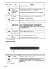
... Push to remove/install the card. Indicates the status of Bluetooth communication. (only for certain models) Backup key Launches Acer Backup Management for your computer. 8 Touchpad Touch-sensitive pointing device which functions like the left and right mouse buttons. *The center... and right speakers deliver stereo audio output. Battery 10 Click buttons (left and right buttons function like a computer mouse. 9 Power Indicates the computer's power status. Indicates the computer's battery status. 1. with mute and hold keys. Only one card can operate at any given time...
... Push to remove/install the card. Indicates the status of Bluetooth communication. (only for certain models) Backup key Launches Acer Backup Management for your computer. 8 Touchpad Touch-sensitive pointing device which functions like the left and right mouse buttons. *The center... and right speakers deliver stereo audio output. Battery 10 Click buttons (left and right buttons function like a computer mouse. 9 Power Indicates the computer's power status. Indicates the computer's battery status. 1. with mute and hold keys. Only one card can operate at any given time...
Acer Aspire 7535 Notebook Service Guide
Page 18
... AC mode. 10 Chapter 1 Battery Indicates the computer's battery status. 1. Charging: The light shows amber when the battery is charging. 2. Icon Function Description Power Indicates the computer's power status. NOTE: 1. Fully charged: The light shows green when in AC mode. Note: Do not cover or obstruct the opening of the fan. Charging...
... AC mode. 10 Chapter 1 Battery Indicates the computer's battery status. 1. Charging: The light shows amber when the battery is charging. 2. Icon Function Description Power Indicates the computer's power status. NOTE: 1. Fully charged: The light shows green when in AC mode. Note: Do not cover or obstruct the opening of the fan. Charging...
Acer Aspire 7535 Notebook Service Guide
Page 23
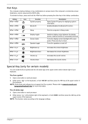
... the US dollar sign at the upper-center of the computer's controls like screen brightness, volume output and the BIOS utility. Please refer to save power. Press any key to the language settings. Either press < > at the bottom-right of the keyboard, or hold and then press the key at the...
... the US dollar sign at the upper-center of the computer's controls like screen brightness, volume output and the BIOS utility. Please refer to save power. Press any key to the language settings. Either press < > at the bottom-right of the keyboard, or hold and then press the key at the...
Acer Aspire 7535 Notebook Service Guide
Page 24
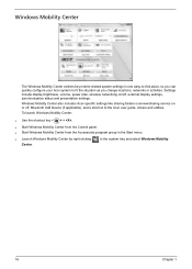
Windows Mobility Center also includes Acer-specific settings like sharing folders overview/sharing service on /off , Bluetooth Add Device (if applicable), and a shortcut to fit the situation as you change locations, networks or activities. Settings include display brightness, volume, power plan, wireless networking on or off , external display settings, synchronization status ... Mobility Center The Windows Mobility Center collects key mobile-related system settings in one easy-to-find place, so you can quickly configure your Acer system to the Acer user guide, drivers and utilities.
Windows Mobility Center also includes Acer-specific settings like sharing folders overview/sharing service on /off , Bluetooth Add Device (if applicable), and a shortcut to fit the situation as you change locations, networks or activities. Settings include display brightness, volume, power plan, wireless networking on or off , external display settings, synchronization status ... Mobility Center The Windows Mobility Center collects key mobile-related system settings in one easy-to-find place, so you can quickly configure your Acer system to the Acer user guide, drivers and utilities.
Acer Aspire 7535 Notebook Service Guide
Page 29
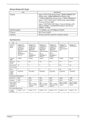
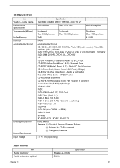
... Peak 1*2MMW MM#895361/Shirley Peak 1*2MMW MM#899541/Shirley Peak 3*3MMW MM#899545 Aspire 7735/7735G/7735Z/7735ZG Series: QMI-AR5B91/ Foxconn Wireless XB63 Aspire 7535/7535G/7235 Series: Foxconn Wireless LAN Atheros AR5B91 1x2 BGN/QMI Wireless LAN Atheros ... Disks 2 Spindle speed (RPM) 5400 RPM Performance Specifications Buffer size 8MB Interface SATA Max. media 540 transfer rate (disk-buffer, Mbytes/s) DC Power Requirements Voltage tolerance 5V(DC) +/- 5% Seagate 2.5" ST9250315AS Toshiba 2.5" Mk2555GSX HGST 2.5" HTS545025B9A3 00 WD 2.5" WD2500BEVT22ZCT0 250000 512 2 2 5400 RPM...
... Peak 1*2MMW MM#895361/Shirley Peak 1*2MMW MM#899541/Shirley Peak 3*3MMW MM#899545 Aspire 7735/7735G/7735Z/7735ZG Series: QMI-AR5B91/ Foxconn Wireless XB63 Aspire 7535/7535G/7235 Series: Foxconn Wireless LAN Atheros AR5B91 1x2 BGN/QMI Wireless LAN Atheros ... Disks 2 Spindle speed (RPM) 5400 RPM Performance Specifications Buffer size 8MB Interface SATA Max. media 540 transfer rate (disk-buffer, Mbytes/s) DC Power Requirements Voltage tolerance 5V(DC) +/- 5% Seagate 2.5" ST9250315AS Toshiba 2.5" Mk2555GSX HGST 2.5" HTS545025B9A3 00 WD 2.5" WD2500BEVT22ZCT0 250000 512 2 2 5400 RPM...
Acer Aspire 7535 Notebook Service Guide
Page 30
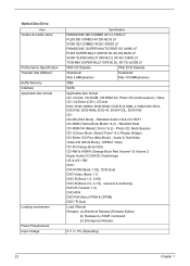
... Release 5 V +/- 5% (Operating) 22 Chapter 1 Optical Disc Drive Item Vendor & model name Performance Specification Transfer rate (KB/sec) Buffer Memory Interface Applicable disc format Loading mechanism Power Requirement Input Voltage Specification PANASONIC BD COMBO 4X UJ-130A LF PLDS BD COMBO 4X DS-4E1S LF SONY BD COMBO 4X BC-5500S LF...
... Release 5 V +/- 5% (Operating) 22 Chapter 1 Optical Disc Drive Item Vendor & model name Performance Specification Transfer rate (KB/sec) Buffer Memory Interface Applicable disc format Loading mechanism Power Requirement Input Voltage Specification PANASONIC BD COMBO 4X UJ-130A LF PLDS BD COMBO 4X DS-4E1S LF SONY BD COMBO 4X BC-5500S LF...
Acer Aspire 7535 Notebook Service Guide
Page 31
... (Yellow Book Mode1 & 2) - Blu-Ray Disc Drive Item Vendor & model name Performance Specification Transfer rate (KB/sec) Buffer Memory Interface Applicable disc format Loading mechanism Power Requirement Input Voltage Specification HLDS BD COMBO DRIVE TRAY DL 4X CT10 LF With CD Disc With DVD Disc With Blu-ray Disc Sustained: Max...
... (Yellow Book Mode1 & 2) - Blu-Ray Disc Drive Item Vendor & model name Performance Specification Transfer rate (KB/sec) Buffer Memory Interface Applicable disc format Loading mechanism Power Requirement Input Voltage Specification HLDS BD COMBO DRIVE TRAY DL 4X CT10 LF With CD Disc With DVD Disc With Blu-ray Disc Sustained: Max...
Acer Aspire 7535 Notebook Service Guide
Page 34
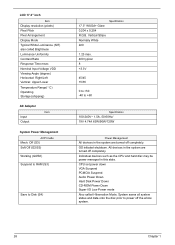
... Disk (S4) 17.3" WXGA+ Glare 0.204 x 0.204 R.G.B. CPU set power down VGA Suspend PCMCIA Suspend Audio Power Down Hard Disk Power Down CD-ROM Power Down Super I/O Low Power mode Also called Brightness Luminance Uniformity Contrast Ratio Response Time msec Nominal Input Voltage VDD...degree) Horizontal: Right/Left Vertical: Upper/Lower Temperature Range( C) Operating Storage (shipping) AC Adaptor Item Input Output System Power Management ACPI mode Mech. OS initiated shutdown. LCD 17.3" inch Item Display resolution (pixels) Pixel Pitch Pixel Arrangement Display Mode Typical White...
... Disk (S4) 17.3" WXGA+ Glare 0.204 x 0.204 R.G.B. CPU set power down VGA Suspend PCMCIA Suspend Audio Power Down Hard Disk Power Down CD-ROM Power Down Super I/O Low Power mode Also called Brightness Luminance Uniformity Contrast Ratio Response Time msec Nominal Input Voltage VDD...degree) Horizontal: Right/Left Vertical: Upper/Lower Temperature Range( C) Operating Storage (shipping) AC Adaptor Item Input Output System Power Management ACPI mode Mech. OS initiated shutdown. LCD 17.3" inch Item Display resolution (pixels) Pixel Pitch Pixel Arrangement Display Mode Typical White...
Acer Aspire 7535 Notebook Service Guide
Page 47
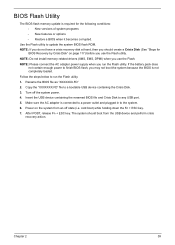
...you may not boot the system because the BIOS is not completely loaded. Power on page 117) before you should boot from an off the system power. 4. Chapter 2 39 BIOS Flash Utility The BIOS flash memory update is connected to a power outlet and plugged in to the system. 6. Rename the BIOS file as...; New versions of system programs • New features or options • Restore a BIOS when it becomes corrupted. If the battery pack does not contain enough power to update the system BIOS flash ROM. NOTE: If you do not have a crisis recovery disk at hand, then you use the Flash. Use the...
...you may not boot the system because the BIOS is not completely loaded. Power on page 117) before you should boot from an off the system power. 4. Chapter 2 39 BIOS Flash Utility The BIOS flash memory update is connected to a power outlet and plugged in to the system. 6. Rename the BIOS file as...; New versions of system programs • New features or options • Restore a BIOS when it becomes corrupted. If the battery pack does not contain enough power to update the system BIOS flash ROM. NOTE: If you do not have a crisis recovery disk at hand, then you use the Flash. Use the...
Acer Aspire 7535 Notebook Service Guide
Page 50
....00F80.723 86.9A554.4R0 86.00F87.735 86.9A552.4R0 86.00H06.622 86.9A553.7R0 86.00G58.725 42 Chapter 3 Turn off the power to any of the sequence to avoid damage to the system and all...
....00F80.723 86.9A554.4R0 86.00F87.735 86.9A552.4R0 86.00H06.622 86.9A553.7R0 86.00G58.725 42 Chapter 3 Turn off the power to any of the sequence to avoid damage to the system and all...
Acer Aspire 7535 Notebook Service Guide
Page 51
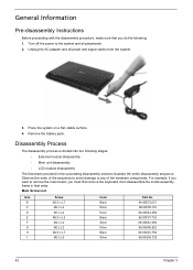
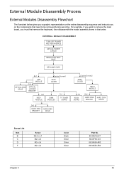
EXTERNAL MODULE DISASSEMBLY TURN OFF POWER AND PERIPHERALS UNPLUG POWER CABLES REMOVE BATTERY PACK SD DUMMY CARD OPTICAL DISK DRIVE Bx1 ODD MODULE Cx1 OPTICAL LOCKER BRACKET Cx1 HDD 1 MODULE Captive Screwx6 BACK COVER DIMM ...
EXTERNAL MODULE DISASSEMBLY TURN OFF POWER AND PERIPHERALS UNPLUG POWER CABLES REMOVE BATTERY PACK SD DUMMY CARD OPTICAL DISK DRIVE Bx1 ODD MODULE Cx1 OPTICAL LOCKER BRACKET Cx1 HDD 1 MODULE Captive Screwx6 BACK COVER DIMM ...
Acer Aspire 7535 Notebook Service Guide
Page 64
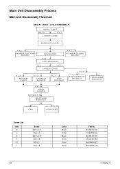
Main Unit Disassembly Process Main Unit Disassembly Flowchart MAIN UNIT DISASSEMBLY MAIN UNIT B x 15 F x 1 LOWER CASE MIDDLE COVER F x 2 POWER BUTTON BOARD KEYBOARD Ex4 LCD MODULE F x 2 POWER SAVING BOARD I x 2 F x 3 UPPER CASE F x 4 F x 2 MODEM CARD C x 2 LAUNCH BOARD F x 1 USB MODULE FINGERPRINT MODULE Fx1 MAIN BOARD SCREW X 4 H E AT S I N K MODULE CPU F x 2 VGA CARD T O U C H PA D MODULE Screw List ...
Main Unit Disassembly Process Main Unit Disassembly Flowchart MAIN UNIT DISASSEMBLY MAIN UNIT B x 15 F x 1 LOWER CASE MIDDLE COVER F x 2 POWER BUTTON BOARD KEYBOARD Ex4 LCD MODULE F x 2 POWER SAVING BOARD I x 2 F x 3 UPPER CASE F x 4 F x 2 MODEM CARD C x 2 LAUNCH BOARD F x 1 USB MODULE FINGERPRINT MODULE Fx1 MAIN BOARD SCREW X 4 H E AT S I N K MODULE CPU F x 2 VGA CARD T O U C H PA D MODULE Screw List ...
Acer Aspire 7535 Notebook Service Guide
Page 66
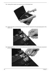
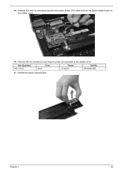
Carefully lift the middle cover and turn it over on the middle cover. 14. Release the latch (a) and disconnect the white media FFC cable (b) from the power saving board on the middle cover. 58 Chapter 3 12. Release the latch (a) and disconnect the black power saving FFC cable (b) from the powersaving board on the keyboard area. 13.
Carefully lift the middle cover and turn it over on the middle cover. 14. Release the latch (a) and disconnect the white media FFC cable (b) from the power saving board on the middle cover. 58 Chapter 3 12. Release the latch (a) and disconnect the black power saving FFC cable (b) from the powersaving board on the keyboard area. 13.
Acer Aspire 7535 Notebook Service Guide
Page 67
Release the latch (a) and disconnect the the power button FFC cable (b) from the power button board on the middle cover. 16. Remove the two screws (F) securing the power saving board to the middle cover. Size (Quantity) Color Torque Part No. M2 x L4 (2) Silver 1.6 kgf-cm 86.9A552.4R0 17. Chapter 3 59 Detach the power saving board. 15.
Release the latch (a) and disconnect the the power button FFC cable (b) from the power button board on the middle cover. 16. Remove the two screws (F) securing the power saving board to the middle cover. Size (Quantity) Color Torque Part No. M2 x L4 (2) Silver 1.6 kgf-cm 86.9A552.4R0 17. Chapter 3 59 Detach the power saving board. 15.
Acer Aspire 7535 Notebook Service Guide
Page 68
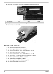
See "Removing the DIMM Module" on page 48. 5. 18. Detach the power button board. See "Removing the Back Cover" on page 53. 9. Torque 1.6 kgf-cm Part No. 86.9A552.4R0 Removing the Keyboard 1. See "Removing the Wireless ... the TV Tuner Card (for certain models only)" on page 46. 4. See "Removing the Middle Cover" on page 48. 6. Remove the two screws (F) securing the power button board to the middle cover. Size (Quantity) M2 x L4 (2) Silver Color 19. See "Removing the Hard Disk Drive 1 (HDD1) Module" on page 57. 60...
See "Removing the DIMM Module" on page 48. 5. 18. Detach the power button board. See "Removing the Back Cover" on page 53. 9. Torque 1.6 kgf-cm Part No. 86.9A552.4R0 Removing the Keyboard 1. See "Removing the Wireless ... the TV Tuner Card (for certain models only)" on page 46. 4. See "Removing the Middle Cover" on page 48. 6. Remove the two screws (F) securing the power button board to the middle cover. Size (Quantity) M2 x L4 (2) Silver Color 19. See "Removing the Hard Disk Drive 1 (HDD1) Module" on page 57. 60...

Acer Aspire 7535 Notebook Service Guide
Page 73
Release the latch (a) and disconnect the Power Button FFC cable (b) from its connector on the main board. Release the latch (a) and disconnect the Power Saving FFC cable (b) from its connector on the main board. 15. Chapter 3 65 14.
Release the latch (a) and disconnect the Power Button FFC cable (b) from its connector on the main board. Release the latch (a) and disconnect the Power Saving FFC cable (b) from its connector on the main board. 15. Chapter 3 65 14.
Acer Aspire 7535 Notebook Service Guide
Page 103
Symptoms cannot be re-created (intermittent problems). Non-Acer products, prototype cards, or modified options can give false errors and invalid system responses. 1. Symptoms (Verified) Power failure. (The power indicator does not go to "Power-On Self-Test (POST) Error Message" on page 98 "Intermittent Problems" on ...the same operation. 3. No beep or error codes are intended to test only Acer products. Go To "Power System Check" on screen. POST detects an error and displayed messages on page 97. "Power-On Self-Test (POST) Error Message" on page 98 "Undetermined Problems" on...
Symptoms cannot be re-created (intermittent problems). Non-Acer products, prototype cards, or modified options can give false errors and invalid system responses. 1. Symptoms (Verified) Power failure. (The power indicator does not go to "Power-On Self-Test (POST) Error Message" on page 98 "Intermittent Problems" on ...the same operation. 3. No beep or error codes are intended to test only Acer products. Go To "Power System Check" on screen. POST detects an error and displayed messages on page 97. "Power-On Self-Test (POST) Error Message" on page 98 "Undetermined Problems" on...
Acer Aspire 7535 Notebook Service Guide
Page 105
.... 4. Boot from the diagnostics diskette and start the diagnostic program (please refer to +20.5V Pin 2: 0V, Ground 1. If you suspect a power problem, see "Undetermined Problems" on the screen, or hang the system. 1. If the voltage is fully installed into the connector. Connect the... and check that the DIMM is within the range, do not work , see "Check the Battery Pack" on page 98 Check the Power Adapter Unplug the power adapter cable from the power adapter does not always indicate a defect. 3. See the following : • Replace the System board. • If the problem is...
.... 4. Boot from the diagnostics diskette and start the diagnostic program (please refer to +20.5V Pin 2: 0V, Ground 1. If you suspect a power problem, see "Undetermined Problems" on the screen, or hang the system. 1. If the voltage is fully installed into the connector. Connect the... and check that the DIMM is within the range, do not work , see "Check the Battery Pack" on page 98 Check the Power Adapter Unplug the power adapter cable from the power adapter does not always indicate a defect. 3. See the following : • Replace the System board. • If the problem is...


