
Service Guide
Page 7
Table of Contents System Specifications 1 Features 1 System Block Diagram 3 Your Acer Notebook tour 4 Front View 4 Closed Front View 5 Rear View 6 Left View 6 Right View 7 ...Utilities 33 DOS Flash Utility 34 WinFlash Utility 36 Remove HDD/BIOS Password Utilities 37 Machine Disassembly and Replacement 43 Disassembly Requirements 43 Pre-disassembly Instructions 44 Disassembly Process 44 External Module Disassembly Process 45 External ... the Switch Cover 57 Removing the Keyboard 58 Removing the LCD Module 59 Removing the Upper Cover 63 Removing the Power Board 67 VII
Table of Contents System Specifications 1 Features 1 System Block Diagram 3 Your Acer Notebook tour 4 Front View 4 Closed Front View 5 Rear View 6 Left View 6 Right View 7 ...Utilities 33 DOS Flash Utility 34 WinFlash Utility 36 Remove HDD/BIOS Password Utilities 37 Machine Disassembly and Replacement 43 Disassembly Requirements 43 Pre-disassembly Instructions 44 Disassembly Process 44 External Module Disassembly Process 45 External ... the Switch Cover 57 Removing the Keyboard 58 Removing the LCD Module 59 Removing the Upper Cover 63 Removing the Power Board 67 VII

Service Guide
Page 8
... 86 Removing the Antennas 88 LCD Module Reassembly Procedure 91 Replacing the Antennas 91 Replacing the LCD Panel 94 Replacing the Camera Module 96 Replacing the LCD Bezel 97 Main Module Reassembly Procedure 99 Replacing the CPU 99 Replacing the CPU Fan 100 Replacing the Thermal Module 100 Replacing the Mainboard 101 Replacing the TouchPad Bracket 102 Replacing the Right Speaker Module 104...
... 86 Removing the Antennas 88 LCD Module Reassembly Procedure 91 Replacing the Antennas 91 Replacing the LCD Panel 94 Replacing the Camera Module 96 Replacing the LCD Bezel 97 Main Module Reassembly Procedure 99 Replacing the CPU 99 Replacing the CPU Fan 100 Replacing the Thermal Module 100 Replacing the Mainboard 101 Replacing the TouchPad Bracket 102 Replacing the Right Speaker Module 104...

Service Guide
Page 54
Remove the battery pack. Disassembly Process IMPORTANT: The LCD Module cannot be replaced. The disassembly process is faulty, such as the camera, antenna or LCD panel, the whole module must first remove the keyboard, then disassemble the inside assembly frame in the succeeding ...avoid damage to remove the mainboard, you do the following stages: • External module disassembly • Main unit disassembly • LCD module disassembly The flowcharts provided in that you must be disassembled outside of the hardware components. Main Screw List Screw Quantity Part Number...
Remove the battery pack. Disassembly Process IMPORTANT: The LCD Module cannot be replaced. The disassembly process is faulty, such as the camera, antenna or LCD panel, the whole module must first remove the keyboard, then disassemble the inside assembly frame in the succeeding ...avoid damage to remove the mainboard, you do the following stages: • External module disassembly • Main unit disassembly • LCD module disassembly The flowcharts provided in that you must be disassembled outside of the hardware components. Main Screw List Screw Quantity Part Number...

Service Guide
Page 101
Replace the adhesive strip to secure the Antenna 3. Run the cable along the cable channel as shown. using all available clips and adhesive. 4. Locating Pin Locating Pin 2. Run the cable down the side of the LCD Module in place. Chapter 3 91 Replace the right Antenna as shown, using all available cable clips. LCD Module Reassembly Procedure Replacing the Antennas 1. Ensure that the locating pins on the Antenna are correctly seated.
Replace the adhesive strip to secure the Antenna 3. Run the cable along the cable channel as shown. using all available clips and adhesive. 4. Locating Pin Locating Pin 2. Run the cable down the side of the LCD Module in place. Chapter 3 91 Replace the right Antenna as shown, using all available cable clips. LCD Module Reassembly Procedure Replacing the Antennas 1. Ensure that the locating pins on the Antenna are correctly seated.

Service Guide
Page 102
Replace the left Antenna as shown, using all available cable clips and adhesive. 92 Chapter 3 Run the cable down the side of the LCD Module in place. Locating Pin Locating Pin 6. using all available clips and adhesive. 8. 5. Replace the adhesive strip to secure the Antenna 7. Run the cable along the cable channel as shown. Ensure that the locating pins on the Antenna are correctly seated.
Replace the left Antenna as shown, using all available cable clips and adhesive. 92 Chapter 3 Run the cable down the side of the LCD Module in place. Locating Pin Locating Pin 6. using all available clips and adhesive. 8. 5. Replace the adhesive strip to secure the Antenna 7. Run the cable along the cable channel as shown. Ensure that the locating pins on the Antenna are correctly seated.

Service Guide
Page 104
Run the cable across the back of the panel and press down the adhesive strip to secure the cable in the LCD Module. 94 Chapter 3 Connect the LCD cable to the panel connector as indicated to avoid trapping when the panel is replaced in place. 4. Run the cable along the back of the panel as shown and press down as shown. 2. Press down as indicated to secure the cable in place. IMPORTANT: Ensure that the LCD cable runs between the green callouts to secure the cable in place. 3. Replacing the LCD Panel 1.
Run the cable across the back of the panel and press down the adhesive strip to secure the cable in the LCD Module. 94 Chapter 3 Connect the LCD cable to the panel connector as indicated to avoid trapping when the panel is replaced in place. 4. Run the cable along the back of the panel as shown and press down as shown. 2. Press down as indicated to secure the cable in place. IMPORTANT: Ensure that the LCD cable runs between the green callouts to secure the cable in place. 3. Replacing the LCD Panel 1.

Service Guide
Page 105
Place the LCD Panel in the LCD Module, top edge first, and secure the LCD cable with the screw holes on each side) in the brackets as shown. 6. Chapter 3 95 5. IMPORTANT: Ensure that the LCD power cable passes through the hinge well and is not trapped under the panel. Align the LCD brackets with adhesive tape. Replace the six screws (three on the panel.
Place the LCD Panel in the LCD Module, top edge first, and secure the LCD cable with the screw holes on each side) in the brackets as shown. 6. Chapter 3 95 5. IMPORTANT: Ensure that the LCD power cable passes through the hinge well and is not trapped under the panel. Align the LCD brackets with adhesive tape. Replace the six screws (three on the panel.

Service Guide
Page 106
Replacing the Camera Module 1. Connect the cable to the camera module. 96 Chapter 3 Secure the LCD module with the two securing screws. Place the camera in the LCD Module. 8. 7. Replace the Camera cable cluster in the LCD Module. 2.
Replacing the Camera Module 1. Connect the cable to the camera module. 96 Chapter 3 Secure the LCD module with the two securing screws. Place the camera in the LCD Module. 8. 7. Replace the Camera cable cluster in the LCD Module. 2.

Service Guide
Page 107
Replace the bezel and press down until there are not trapped by the bezel. IMPORTANT: Ensure that the LCD cables pass through the hinge wells and are no gaps between the bezel and the LCD Module. Chapter 3 97 Replacing the LCD Bezel 1.
Replace the bezel and press down until there are not trapped by the bezel. IMPORTANT: Ensure that the LCD cables pass through the hinge wells and are no gaps between the bezel and the LCD Module. Chapter 3 97 Replacing the LCD Bezel 1.

Service Guide
Page 120
Replacing the LCD Module 1. Ensure that the correct cover is seated correctly in the Upper Cover. 110 Chapter 3 Align the screw holes on the rear of the cover is used. The left screw cover as shown. Replace the left and right screw covers are shaped differently. Ensure that the securing tab on the LCD Module and Upper Cover and replace the LCD Module. 2. Left Screw Cover Right Screw Cover 3. Turn the computer over and replace the eleven screws as shown. 10.
Replacing the LCD Module 1. Ensure that the correct cover is seated correctly in the Upper Cover. 110 Chapter 3 Align the screw holes on the rear of the cover is used. The left screw cover as shown. Replace the left and right screw covers are shaped differently. Ensure that the securing tab on the LCD Module and Upper Cover and replace the LCD Module. 2. Left Screw Cover Right Screw Cover 3. Turn the computer over and replace the eleven screws as shown. 10.

Service Guide
Page 121
Align the left Hinge Cover as shown. two securing clips. Identify the rear edge of the cover is seated correctly in the Upper Cover. 5. Rear Securing Clips 8. Chapter 3 111 Ensure that the securing tab on the rear of the covers by the down to the Upper Cover. 6. Ensure that the Hinge Covers are replaced 7. Repeat the process for the right side Hinge Cover. Replace the right screw cover as shown and press correctly. 4. Replace the four screws securing the LCD Module to replace the cover.
Align the left Hinge Cover as shown. two securing clips. Identify the rear edge of the cover is seated correctly in the Upper Cover. 5. Rear Securing Clips 8. Chapter 3 111 Ensure that the securing tab on the rear of the covers by the down to the Upper Cover. 6. Ensure that the Hinge Covers are replaced 7. Repeat the process for the right side Hinge Cover. Replace the right screw cover as shown and press correctly. 4. Replace the four screws securing the LCD Module to replace the cover.

Service Guide
Page 122
9. Run the black Antenna cable along the cable channel as all available cable clips. Replace the adhesive strip to the Mainboard as shown using all available retaining clips. 12. Connect the LCD cable to secure the cable in place. 11. shown. 112 Chapter 3 Run the LCD cable along the cable channel as shown using 13. Run the white Antenna cable along the cable channel using all available retaining clips. 10.
9. Run the black Antenna cable along the cable channel as all available cable clips. Replace the adhesive strip to the Mainboard as shown using all available retaining clips. 12. Connect the LCD cable to secure the cable in place. 11. shown. 112 Chapter 3 Run the LCD cable along the cable channel as shown using 13. Run the white Antenna cable along the cable channel using all available retaining clips. 10.

Service Guide
Page 124
17. Replace the two screws securing the LCD Module to the Lower Cover. 114 Chapter 3
17. Replace the two screws securing the LCD Module to the Lower Cover. 114 Chapter 3

Service Guide
Page 135
Do not replace a non-defective FRUs: No POST or Video If the POST or video doesn't display, perform the following occurs: • Fans start up • Status LEDs light up If there is no power, see "LCD Failure" on page 124. 3. Make sure that the internal display is discovered. 6. Reference Product pages for...
Do not replace a non-defective FRUs: No POST or Video If the POST or video doesn't display, perform the following occurs: • Fans start up • Status LEDs light up If there is no power, see "LCD Failure" on page 124. 3. Make sure that the internal display is discovered. 6. Reference Product pages for...
Service Guide
Page 136
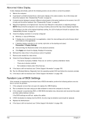
.... If the display is too dim at the highest brightness setting, the LCD is correctly configured: a. If the BIOS settings are no red Xs or yellow exclamation marks. • There are still lost, replace the cables. 4. If extensive pixel damage is present (different colored spots...Video Display If video displays abnormally, perform the following actions one year old, replace the CMOS battery. 2. Reboot the computer. 2. If permanent vertical/horizontal lines or dark spots display in the same location, the LCD is not normal, right-click on page 185. 126 Chapter 4 See "...
.... If the display is too dim at the highest brightness setting, the LCD is correctly configured: a. If the BIOS settings are no red Xs or yellow exclamation marks. • There are still lost, replace the cables. 4. If extensive pixel damage is present (different colored spots...Video Display If video displays abnormally, perform the following actions one year old, replace the CMOS battery. 2. Reboot the computer. 2. If permanent vertical/horizontal lines or dark spots display in the same location, the LCD is not normal, right-click on page 185. 126 Chapter 4 See "...
Service Guide
Page 137
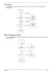
Do not replace a nondefective FRUs: Built-In Keyboard Failure If the built-in Keyboard fails, perform the following actions one at a time to correct the problem. LCD Failure If the LCD fails, perform the following actions one at a time to correct the problem. Do not replace a non-defective FRUs: Chapter 4 127
Do not replace a nondefective FRUs: Built-In Keyboard Failure If the built-in Keyboard fails, perform the following actions one at a time to correct the problem. LCD Failure If the LCD fails, perform the following actions one at a time to correct the problem. Do not replace a non-defective FRUs: Chapter 4 127

Service Guide
Page 146
...whether a short circuit is suspected, or whether the system is detected, replace the FRU. Power-on page 124.): 1. If no more errors. Follow these procedures to do the following devices: • Non-Acer devices • Printer, mouse, and other external devices • Battery ...be considered only when a recurring problem exists. Remove or disconnect all attached devices are found, replace the FRU. 3. Do not replace a non-defective FRU: • System board • LCD assembly 136 Chapter 4 If any error is inoperative. When analyzing an intermittent problem, do with ...
...whether a short circuit is suspected, or whether the system is detected, replace the FRU. Power-on page 124.): 1. If no more errors. Follow these procedures to do the following devices: • Non-Acer devices • Printer, mouse, and other external devices • Battery ...be considered only when a recurring problem exists. Remove or disconnect all attached devices are found, replace the FRU. 3. Do not replace a non-defective FRU: • System board • LCD assembly 136 Chapter 4 If any error is inoperative. When analyzing an intermittent problem, do with ...

Service Guide
Page 198
Removing 58 Replacing 115 Keyboard Failure 127 L LCD Bezel Removing 82 Replacing 97 LCD Brackets Removing 86 Replacing 94 LCD Cable Replacing 94 LCD Failure 127 LCD Module Removing 59 Replacing 110 LCD Module Disassembly Flowchart 81 LCD Module Reassembly Procedure 91 LCD Panel Removing 84 Replacing 94 Left Speaker Module Removing 68 Replacing 105 Lower Covers Removing 48 Replacing 119 M Main Unit Disassembly Flowchart 56 Mainboard...
Removing 58 Replacing 115 Keyboard Failure 127 L LCD Bezel Removing 82 Replacing 97 LCD Brackets Removing 86 Replacing 94 LCD Cable Replacing 94 LCD Failure 127 LCD Module Removing 59 Replacing 110 LCD Module Disassembly Flowchart 81 LCD Module Reassembly Procedure 91 LCD Panel Removing 84 Replacing 94 Left Speaker Module Removing 68 Replacing 105 Lower Covers Removing 48 Replacing 119 M Main Unit Disassembly Flowchart 56 Mainboard...

Service Guide
Page 199
Thermal Unit Failure 134 TouchPad Removing 72 TouchPad Bracket Removing 72 Replacing 102 TouchPad Failure 128 Troubleshooting Built-in KB Failure 127 EasyTouch Buttons 134 HDTV Switch 135 Internal Microphone 129 Internal Speakers 128 LCD Failure 127 No Display 125 ODD 131 Other Failures 135 Power On 124 Thermal Unit 134 TouchPad 128 WLAN 134 U Undetermined Problems 136 Upper Cover Removing 63 Replacing 106 utility BIOS 21-33 W Windows 2000 Environment Test 182 Wireless Function Failure 134 WLAN Module Removing 52 Replacing 118 189
Thermal Unit Failure 134 TouchPad Removing 72 TouchPad Bracket Removing 72 Replacing 102 TouchPad Failure 128 Troubleshooting Built-in KB Failure 127 EasyTouch Buttons 134 HDTV Switch 135 Internal Microphone 129 Internal Speakers 128 LCD Failure 127 No Display 125 ODD 131 Other Failures 135 Power On 124 Thermal Unit 134 TouchPad 128 WLAN 134 U Undetermined Problems 136 Upper Cover Removing 63 Replacing 106 utility BIOS 21-33 W Windows 2000 Environment Test 182 Wireless Function Failure 134 WLAN Module Removing 52 Replacing 118 189


