
Acer Aspire 7250 Service Guide
Page 65
... applied during the replacement and reassembly process. 3-5 The product previews seen in size. During the disassembly process, group the screws with the corresponding components to disassemble the notebook computer for maintenance and troubleshooting. Machine Disassembly and Replacement 0 This chapter contains step-by-step procedures on how to avoid mismatch when putting ...channels and clips are used and that the cables are suggested: Wrist grounding strap and conductive mat for the different components vary in the disassembly procedures may not represent the actual model.
... applied during the replacement and reassembly process. 3-5 The product previews seen in size. During the disassembly process, group the screws with the corresponding components to disassemble the notebook computer for maintenance and troubleshooting. Machine Disassembly and Replacement 0 This chapter contains step-by-step procedures on how to avoid mismatch when putting ...channels and clips are used and that the cables are suggested: Wrist grounding strap and conductive mat for the different components vary in the disassembly procedures may not represent the actual model.

Acer Aspire 7250 Service Guide
Page 66
Pre-disassembly Instructions 0 Before proceeding with the disassembly procedure, make sure to the system and all power and signal cables from the system. Unplug the AC adapter and all peripherals. 2. AC Adapter 3. Turn off the power to do the following: 1. Place the system on a flat, stable surface. 3-6 Figure 3-1.
Pre-disassembly Instructions 0 Before proceeding with the disassembly procedure, make sure to the system and all power and signal cables from the system. Unplug the AC adapter and all peripherals. 2. AC Adapter 3. Turn off the power to do the following: 1. Place the system on a flat, stable surface. 3-6 Figure 3-1.
Acer Aspire 7250 Service Guide
Page 67
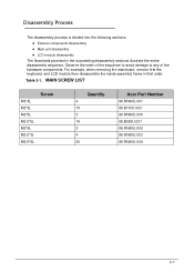
MAIN SCREW LIST M3*4L M2*3L M2*5L M2.5*5L M2*6L M2.5*3L M2.5*6L Screw Quantity 4 15 3 16 2 4 30 Acer Part Number 86.RN60U.001 86.B110U.003 86.RN60U.005 86.B050U.001 86.RN60U.002 86.RN60U.003 86.RN60U.004 3-7 Table 3-1. For ...example, when removing the mainboard, remove first the keyboard, and LCD module then disassemble the inside assembly frame in the succeeding disassembly sections illustrate the entire disassembly sequence. Observe the order of the sequence to avoid damage to any of the hardware components...
MAIN SCREW LIST M3*4L M2*3L M2*5L M2.5*5L M2*6L M2.5*3L M2.5*6L Screw Quantity 4 15 3 16 2 4 30 Acer Part Number 86.RN60U.001 86.B110U.003 86.RN60U.005 86.B050U.001 86.RN60U.002 86.RN60U.003 86.RN60U.004 3-7 Table 3-1. For ...example, when removing the mainboard, remove first the keyboard, and LCD module then disassemble the inside assembly frame in the succeeding disassembly sections illustrate the entire disassembly sequence. Observe the order of the sequence to avoid damage to any of the hardware components...

Acer Aspire 7250 Service Guide
Page 79
Screws Step TOP CASE Disassembly ODD AND IO BD ODD AND IO BD Main board module M2.5*3L M2*2L M2.5*5L M2*5L M2*5L M2.5*5L Screw Quantity Part No. 4 86.RN60U.003 4 86.RN60U.006 2 86.B050U.001 2 86.RN60U.005 5 86.RN60U.005 2 86.B050U.001 3-19 Main Unit Disassembly Process 0 Main Unit Disassembly Flowchart 0 Figure 3-23. Main Unit DIsassembly Flowchart Table 3-3.
Screws Step TOP CASE Disassembly ODD AND IO BD ODD AND IO BD Main board module M2.5*3L M2*2L M2.5*5L M2*5L M2*5L M2.5*5L Screw Quantity Part No. 4 86.RN60U.003 4 86.RN60U.006 2 86.B050U.001 2 86.RN60U.005 5 86.RN60U.005 2 86.B050U.001 3-19 Main Unit Disassembly Process 0 Main Unit Disassembly Flowchart 0 Figure 3-23. Main Unit DIsassembly Flowchart Table 3-3.

Acer Aspire 7250 Service Guide
Page 130
... alone as this may reduce display brightness. 2. If permanent vertical/horizontal lines or dark spots appear in the application. Refer to Disassembly Process). 11. Check the display resolution is listed under Other Devices 7. There are no red Xs or yellow exclamation marks There ... brightness setting, the LCD is faulty and should be replaced. Refer to the desired resolution. Click and drag the Resolution slider to Disassembly Process. Refer to its highest level. Click Apply and check the display. Abnormal Video 0 If the video appears abnormal, perform the...
... alone as this may reduce display brightness. 2. If permanent vertical/horizontal lines or dark spots appear in the application. Refer to Disassembly Process). 11. Check the display resolution is listed under Other Devices 7. There are no red Xs or yellow exclamation marks There ... brightness setting, the LCD is faulty and should be replaced. Refer to the desired resolution. Click and drag the Resolution slider to Disassembly Process. Refer to its highest level. Click Apply and check the display. Abnormal Video 0 If the video appears abnormal, perform the...


